They will be setting up a miniature house using snap circuits, and will program the different appliances via ESP32, notably to:
monitor environmental parameters (temperature humidity) in real time
control appliances remotely via BlynkSommaire
- 1 Introduction
- 2 Étape 1 - Setting up the miniature IoT house
- 3 Étape 2 - Monitoring temperature, humidity and light with Blynk
- 4 Étape 3 - Create a new project in the Blynk app
- 5 Étape 4 - Choose Your Hardware
- 6 Étape 5 - Auth Token
- 7 Étape 6 - Configure Value Display widgets
- 8 Étape 7 - Programming the ESP32
- 9 Étape 8 - Controlling miniature appliances remotely via Blynk
- 10 Étape 9 - Create a new project in the Blynk app
- 11 Étape 10 - Choose Your Hardware
- 12 Étape 11 - Auth Token
- 13 Étape 12 - Program the ESP32 board
- 14 Étape 13 - Set up the Blynk app
- 15 Commentaires
Introduction
Energy efficiency can be affected by the position of the house with respect to the sun, the prevailing wind, etc.
Thus, for example, to increase energy efficiency, one will want to position a house facing towards the south, so that the sun rays can provide natural illumination.
Other factors to take into consideration in order to maximize energy efficiency are directly related to the appliances you use.
Here’s a few tips:
- use smart appliances, for example lights bulbs that go on at night and automatically turn off during the day
- use smart plugs equipped with an on off button that can be programmed to turn on and off at specific times.
- hook your appliances to the internet so that you can control them remotely from any location.
Matériaux
Outils
Étape 1 - Setting up the miniature IoT house
To begin with, kids will need to build or assemble a miniature house. They can build one using cardboard, or you can laser cut them in advance, using for example a 3mm thick MDF board. Here’s the design of a miniature house, ready for laser cut.
Étape 2 - Monitoring temperature, humidity and light with Blynk
kids will be setting up a Blynk project that enables them to monitor the parameters recorded by temp/humidity and light sensors located in their miniature house.
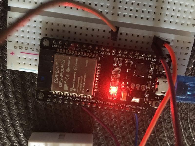
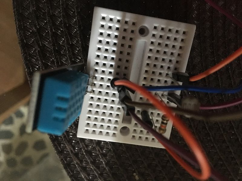
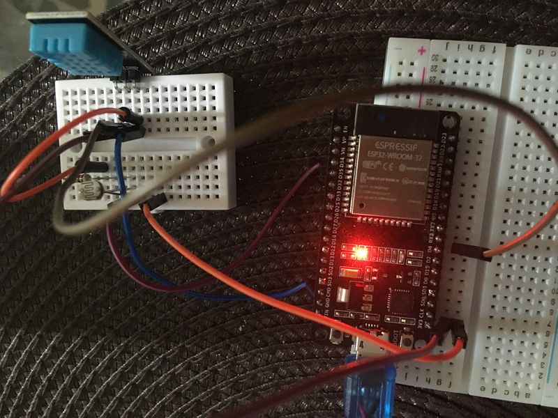
First, hook up the LDR snap and the DHT snap to the ESP32 board. connect Data pin of the DHT sensor to pin 4 on the ESP32 board. Connect the LDR snap to pin 34 on the ESP32.
Next, you ll have to create a Blynk project and configure it to display the values recorded by the temp/hum sensor.
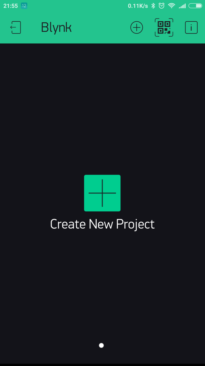
Étape 3 - Create a new project in the Blynk app
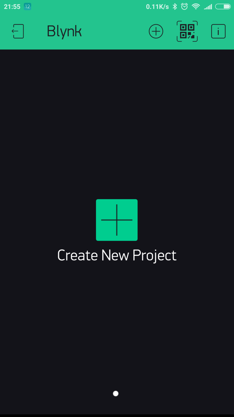
After you’ve successfully logged into your account, start by creating a new project.
Étape 4 - Choose Your Hardware
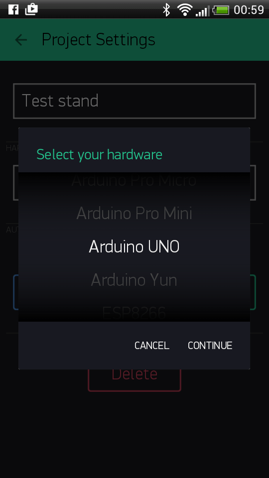
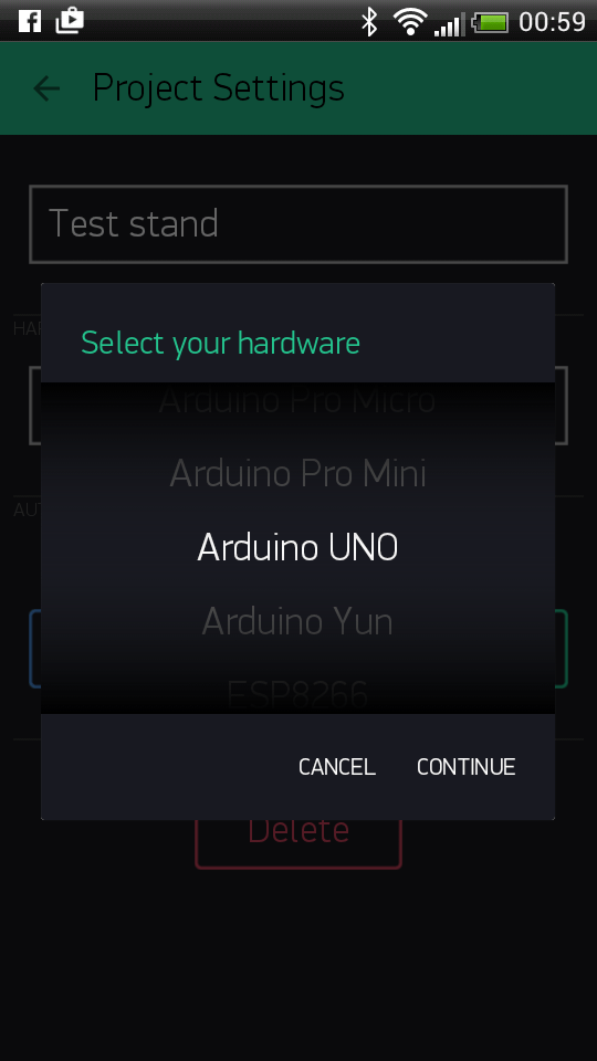
Select the hardware model you will use. If you are following this tutorial you ll probably be using an ESP32 board.
Étape 5 - Auth Token
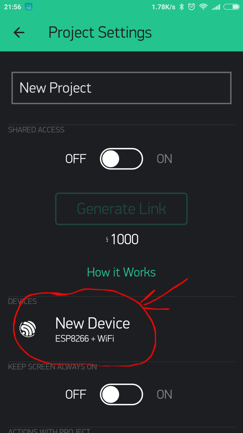
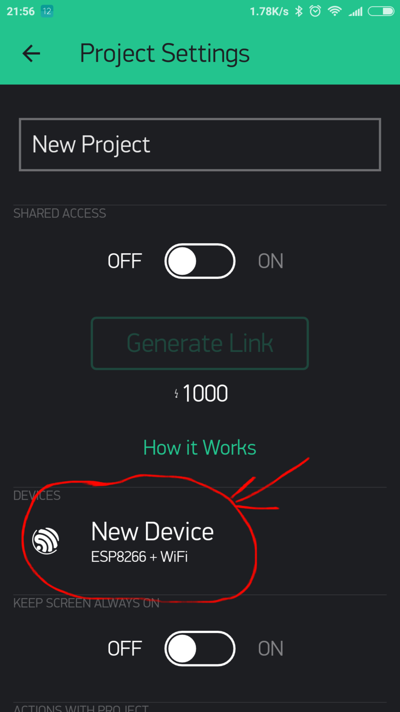
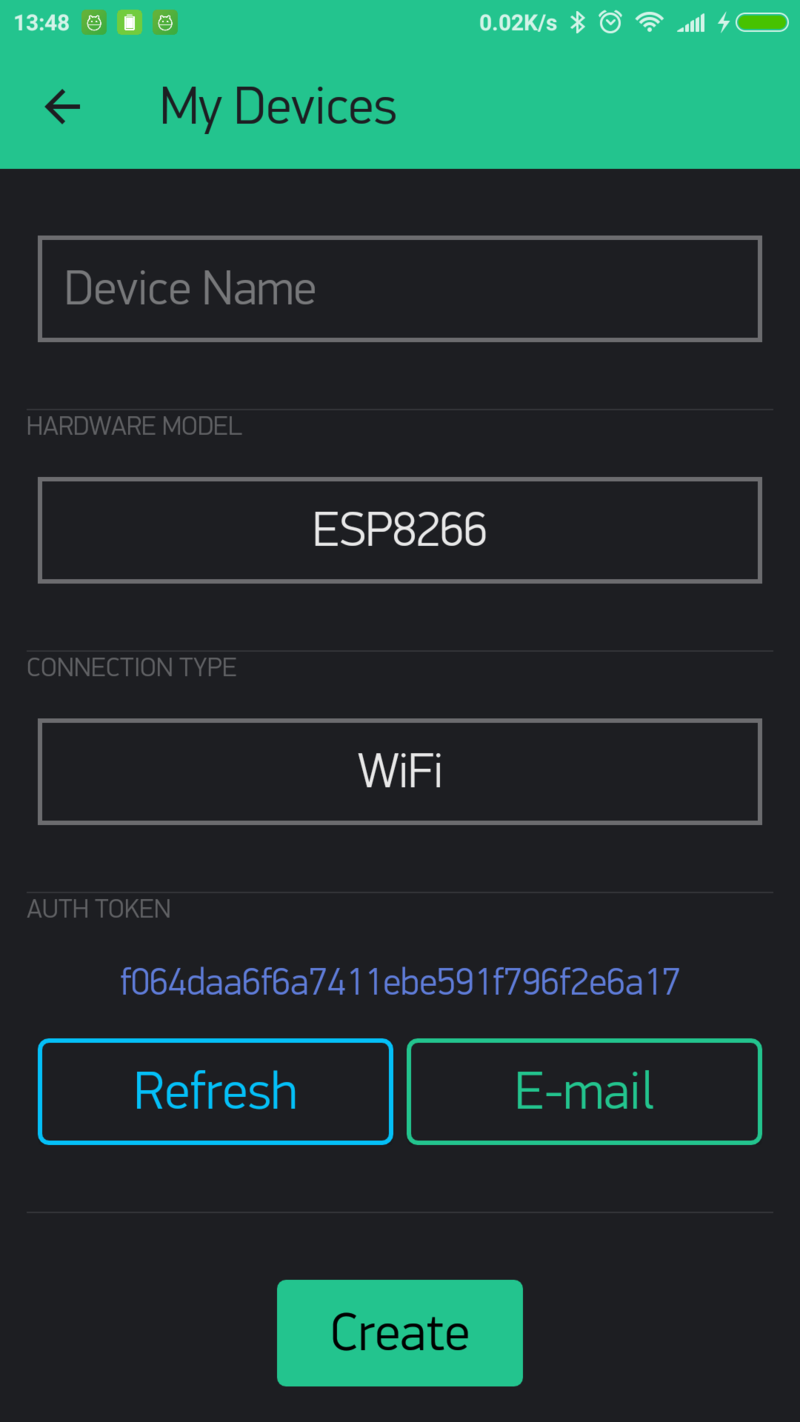
Auth Token is a unique identifier which is needed to connect your hardware to your smartphone. Every new project you create will have its own Auth Token. You’ll get Auth Token automatically on your email after project creation. You can also copy it manually. Click on devices section and selected required device:
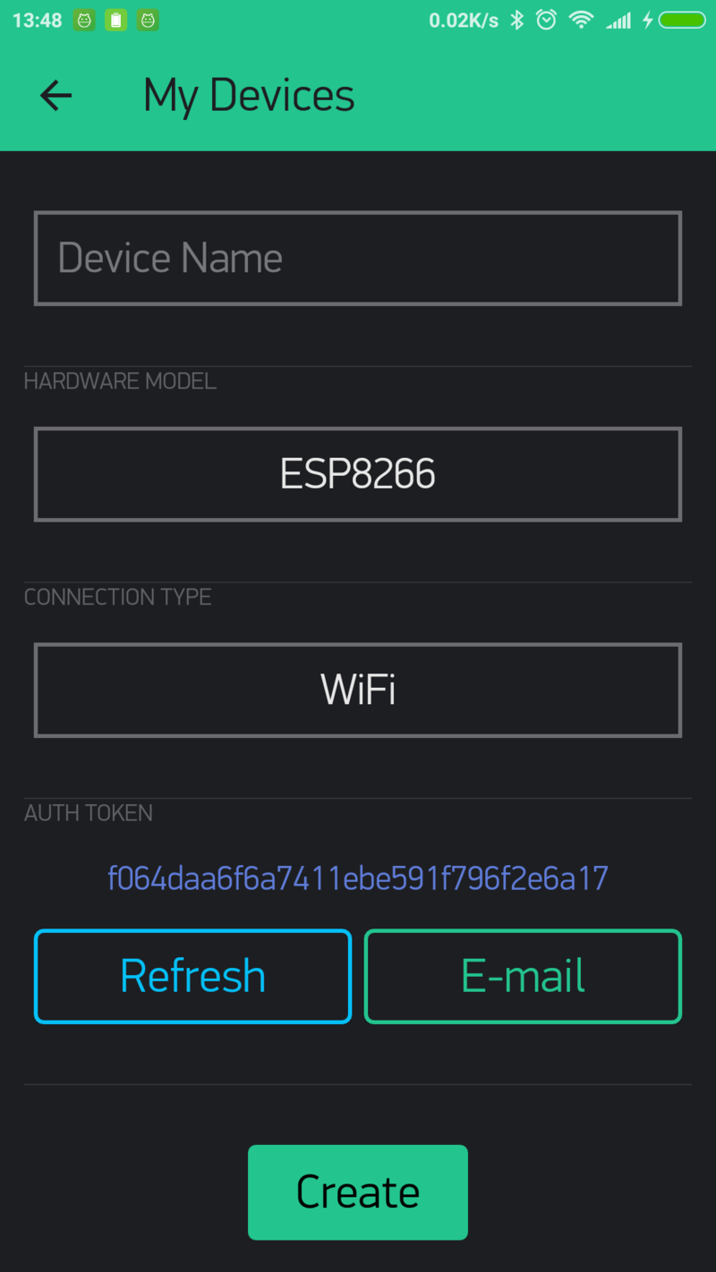
And you’ll see token :
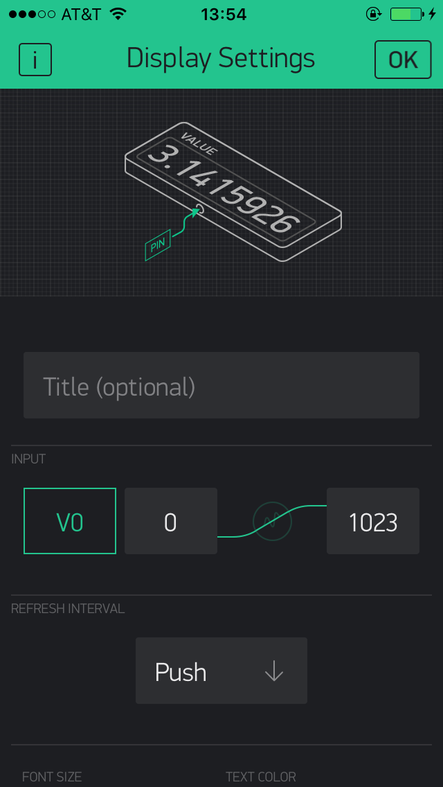
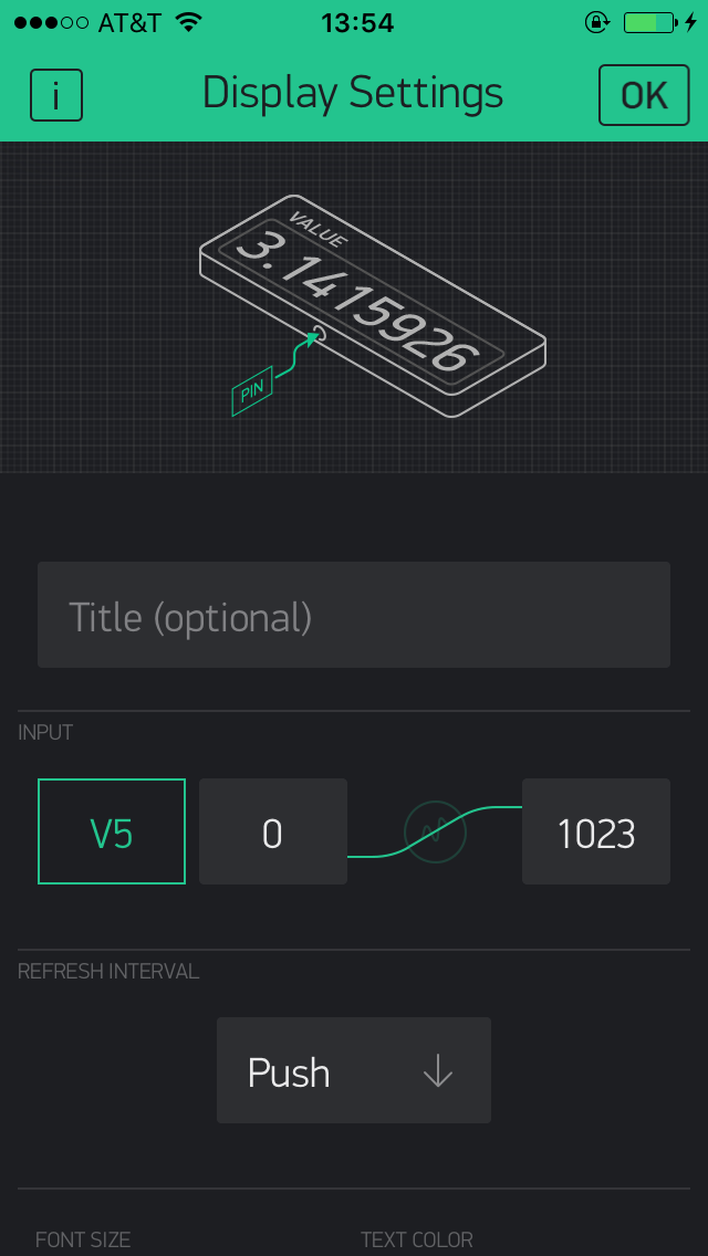
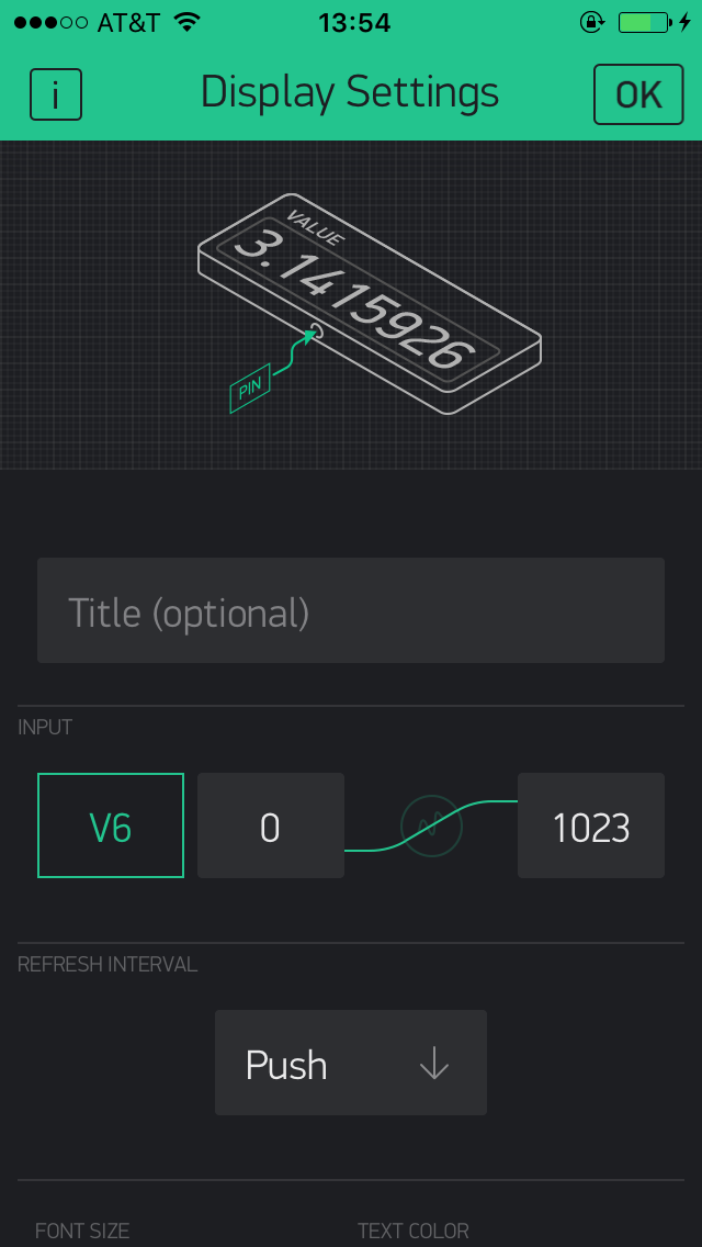
Étape 6 - Configure Value Display widgets
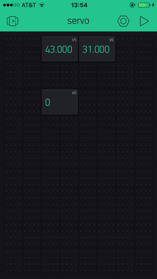
Drag and drop 3 value Display widgets
configure them as follows:
- set input as V5, from 0 to 1023. Set refresh interval as Push
- set input as V6, from 0 to 1023. Set refresh interval as Push
- set input as V0, from 0 to 1023. Set refresh interval as Push
The first display widget will be receiving humidity values from the DHT sensor, and displaying them on the app; the second display widget will be receiving temperature values over wi-fi, the third display widget will be displaying values of light recorded by the LDR sensor.
Étape 7 - Programming the ESP32
Launch Arduino IDE, select the correct board and port -under the “Tools” menu-.
Paste the code below into the software and upload it onto the board.
#define BLYNK_PRINT Serial
#include <WiFi.h>
#include <WiFiClient.h>
#include <BlynkSimpleEsp32.h>
#include <DHT.h>
// You should get Auth Token in the Blynk App.
// Go to the Project Settings (nut icon).
char auth[] = "726e035ec85946ad82c3a2bb03015e5f";
// Your WiFi credentials.
// Set password to "" for open networks.
char ssid[] = "TISCALI-301DC1";
char pass[] = "ewkvt+dGc1Mx";
const int analogPin = 34; // Analog input pin 0 (GPIO 36)
int sensorValue = 0; // Value read from the ADC
#define DHTPIN 4 // What digital pin we're connected to
// Uncomment whatever type you're using!
#define DHTTYPE DHT11 // DHT 11
//#define DHTTYPE DHT22 // DHT 22, AM2302, AM2321
//#define DHTTYPE DHT21 // DHT 21, AM2301
DHT dht(DHTPIN, DHTTYPE);
BlynkTimer timer;
// This function sends Arduino's up time every second to Virtual Pin (5).
// In the app, Widget's reading frequency should be set to PUSH. This means
// that you define how often to send data to Blynk App.
void sendSensor()
{
float h = dht.readHumidity();
float t = dht.readTemperature(); // or dht.readTemperature(true) for Fahrenheit
if (isnan(h)
Étape 8 - Controlling miniature appliances remotely via Blynk
The last part of the activity will be about controlling the electrical appliances one by one remotely via the blynk app.
Each miniature house will need to include at least one miniature light bulb as well as another appliance (ex. miniature 3D printer, miniature oven).
Being able to remotely control one s appliances gives the user the obvious advantage of being able to choosing when they're running and when they aren’t, thus contributing to saving energy and making the miniature house as energy efficient as possible.
We've designed a number of 3D printable miniature electronic appliances that can be placed on top of a snap component. You can for example imagine to place the miniature oven on top of a Led or a miniature 3D printer on top of a mini vibrating motor snap, thus emulating real-life operations of those appliances.
Find all appliances available for 3D printing by clicking on the links below:
This activity will require the Blynk application. So, first download Blynk on your smartphone.
Étape 9 - Create a new project in the Blynk app
After you’ve successfully logged into your account, start by creating a new project.
Étape 10 - Choose Your Hardware
Select the hardware model you will use. If you are following this tutorial you ll probably be using an ESP32 board.
Étape 11 - Auth Token
Auth Token is a unique identifier which is needed to connect your hardware to your smartphone. Every new project you create will have its own Auth Token. You’ll get Auth Token automatically on your email after project creation. You can also copy it manually. Click on devices section and selected required device:
And you’ll see token :
Étape 12 - Program the ESP32 board
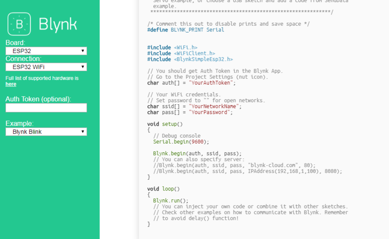
head to this website, select your hardware, the connection mode (ex. wi-fi) and choose the Blynk Blink example.
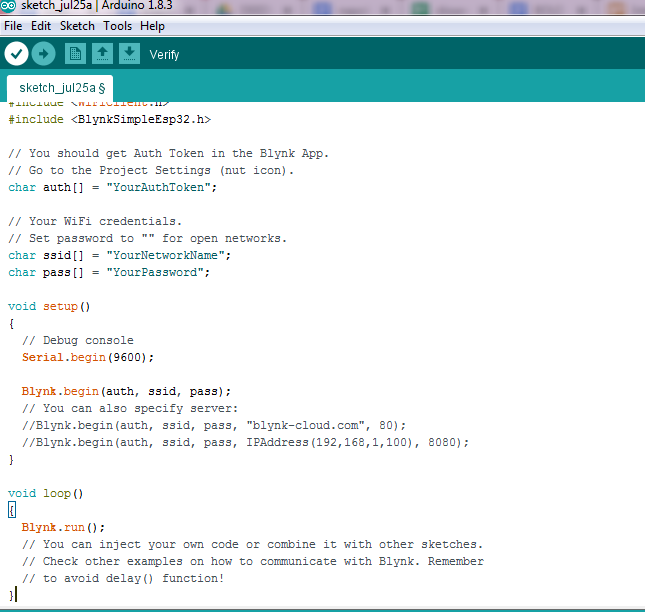
Copy the code and paste it on Arduino IDE (prior to that, make sure you select the correct board and the correct port - under “Tools”-).
Replace “YourAuthtoken” with the token available on the app, replace “YourNetworkName” and “YourPassword” with your wi-fi credentials.
Finally, upload the code onto the board.
Étape 13 - Set up the Blynk app
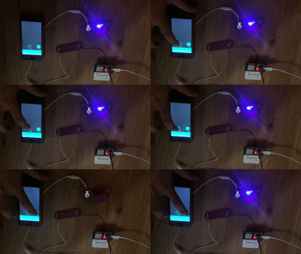
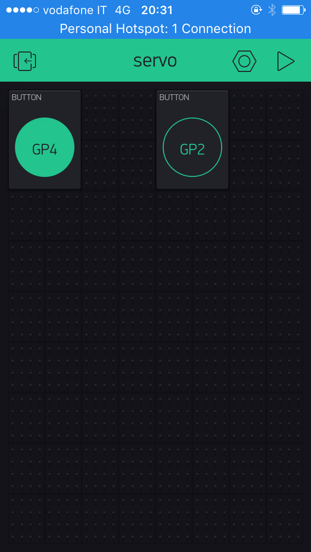
In your Blynk project, choose button widgets, as many buttons as you have snaps to control remotely. In our example we’ll add two buttons widgets since we have two snap parts to control (both are LEDs).
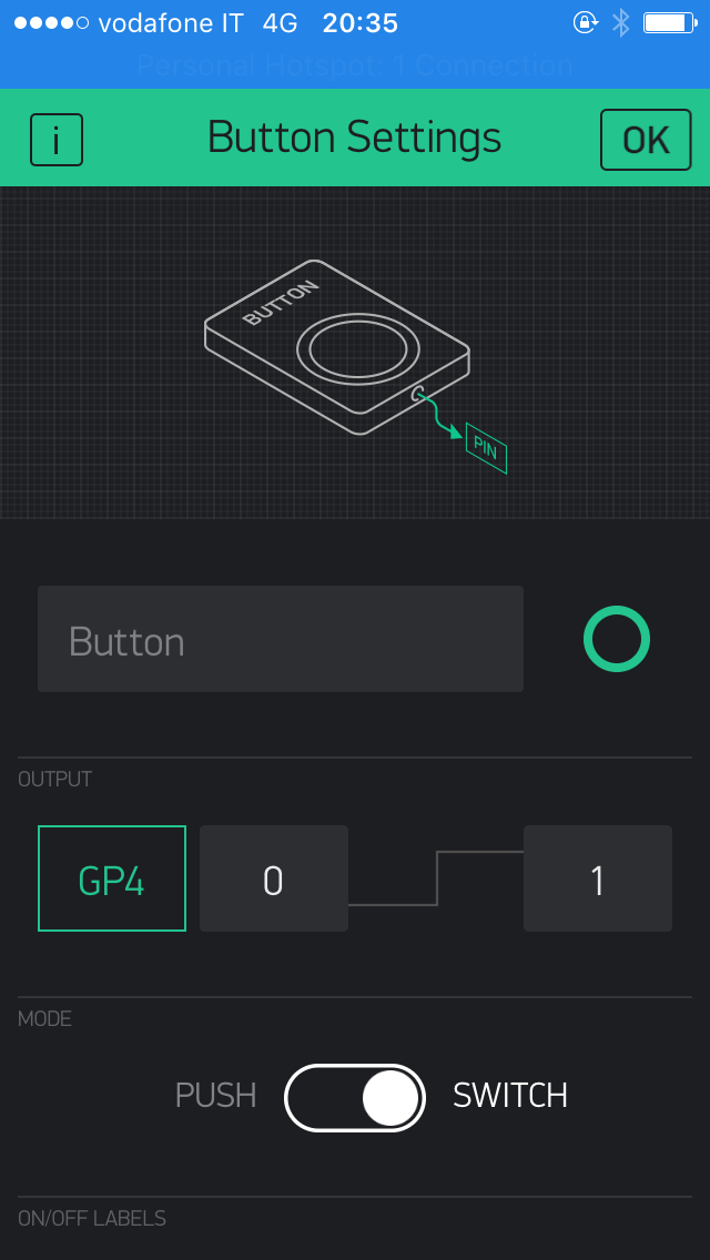
Next select the first button and, under output, choose the port to which one of your snap is connected to the ESP32 board (ex. GP4). Make sure to have 0 and 1 next to GP4, just like in the picture below. You can also choose whether the button will function in mush or switch mode.
Do the same for the second button, only this time connect to the relevant ESP32 pin (ex. GP2).
Draft
 Français
 English
 Deutsch
 Español
 Italiano
 Português