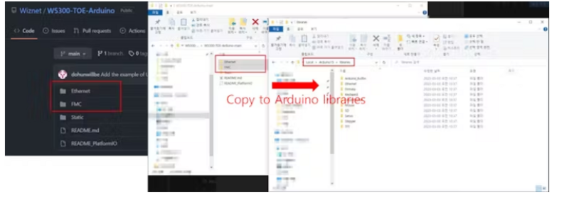
Étape 4 - To add the "Ethernet" and "FMC" libraries to your Arduino IDE, follow these steps
Download or clone the library repositories for "Ethernet" and "FMC" from their respective sources (GitHub or other repositories) to your computer.
Locate the "libraries" folder within the "Arduino15" directory on your computer. The exact path may vary depending on your PC environment. It's usually in a location similar to this:
makefile
C:\Users\YOUR_NAME\AppData\Local\Arduino15\libraries
Inside the "libraries" folder, create two new folders: one named "Ethernet" and the other named "FMC."
Copy the contents of the downloaded or cloned "Ethernet" library repository into the "Ethernet" folder you created in the "libraries" directory.
Similarly, copy the contents of the downloaded or cloned "FMC" library repository into the "FMC" folder you created in the "libraries" directory.
After copying the library files into their respective folders, you should have a directory structure similar to this:
Arduino15/libraries/Ethernet Arduino15/libraries/FMC
Close and reopen the Arduino IDE to ensure that it recognizes the newly added libraries.
Now, you should be able to use the "Ethernet" and "FMC" libraries in your Arduino sketches for your STM32 project.
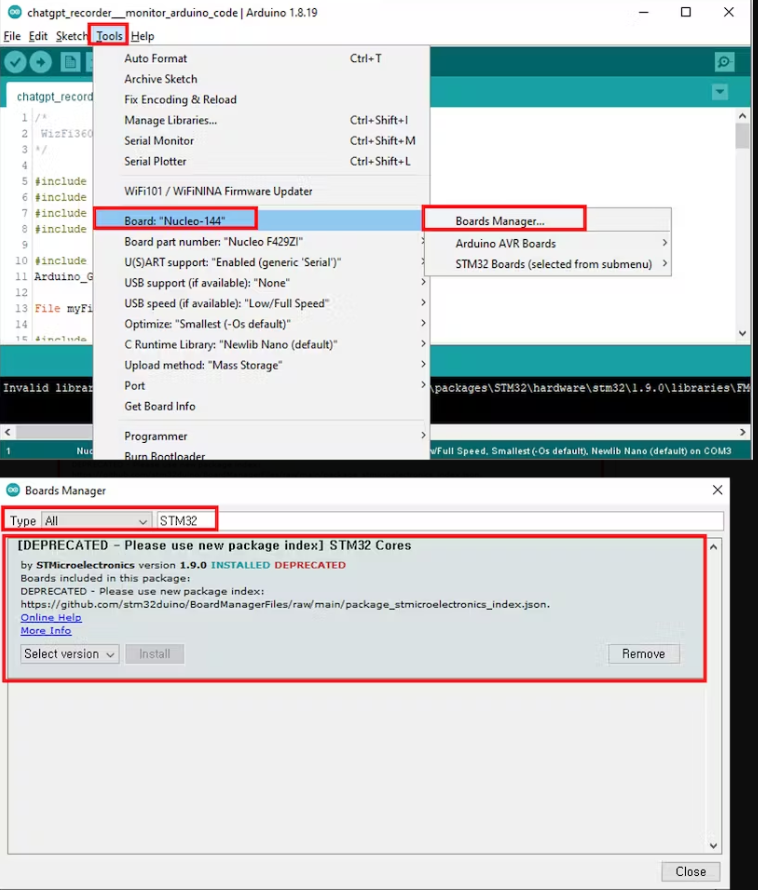
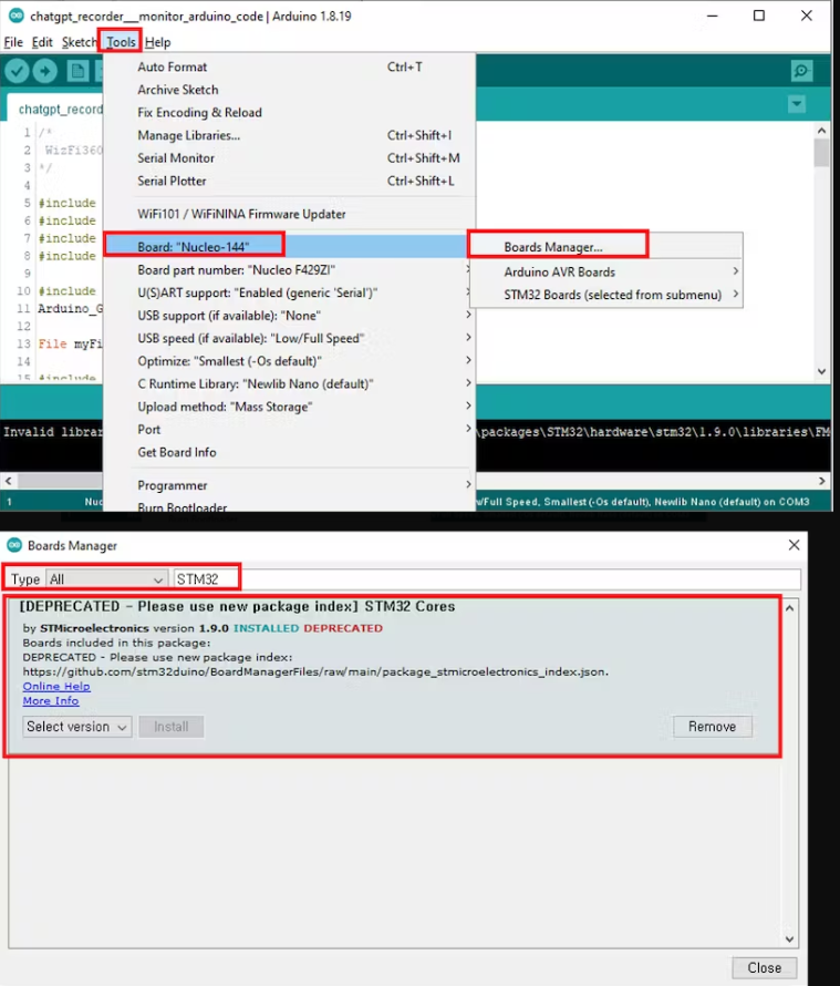
Step 3: To install the STM32 core library and configure the board settings for your STM32 Nucleo-144 board in the Arduino IDE, follow these steps:
1. Open the Arduino IDE on your computer.
2. In the Arduino IDE, go to the "Tools" menu.
3. Select the "Board" submenu.
4. Choose "Board Manager..." from the submenu. This will open the Arduino Board Manager.
5. In the "Board Manager, " type "STM32" in the search bar to filter the available packages.
6. Look for "STM32 Cores" in the list of available packages.
7. Click the "Install" button next to "STM32 Cores" to start the installation process.
8. Wait for the installation to complete. This might take a few minutes, depending on your internet connection speed.
9. Once the installation is finished, close the Arduino IDE and reopen it to ensure that the STM32 core libraries are properly recognized.
10. To configure the board settings for your STM32 Nucleo-144 board, go to the "Tools" menu again.
11. In the "Board" submenu, select "Nucleo-144" as your target board.
With these steps completed, your Arduino IDE should be configured to work with STM32 microcontrollers, and you can select your specific STM32 Nucleo-144 board as the target for your projects.
How To Use STM32F207ZG(NUCLEO-F207ZG) with Wiznet ToE 5300 in the Project
Given the unavailability of the NUCLEO-F429ZI board, which is officially supported by the Wiznet W5300 library, it's prudent to consider alternative hardware options recommended by Wiznet. Here's a technical approach to finding suitable alternatives:
1. Review Wiznet's Compatibility Documentation: Carefully review Wiznet's official documentation, datasheets, and compatibility guides for the W5300 library. Look for mentions of compatible development boards, microcontrollers, or platforms that are recommended or certified for use with the W5300.
2. Check Microcontroller Compatibility: Verify if other STM32 microcontrollers are compatible with the W5300 library. Explore STM32 datasheets and reference manuals to identify microcontrollers with similar features and pin configurations as the NUCLEO-F429ZI.
3. Evaluate Hardware Availability: Investigate the current availability of alternative STM32 Nucleo boards or development kits that meet the compatibility criteria specified by Wiznet. Look for boards that offer Ethernet connectivity and support for the W5300 library.
4. Consider Evaluation Boards: Examine STM32 evaluation boards or development kits that include Ethernet connectivity. Some of these boards may align with Wiznet's recommendations and can be used as a suitable alternative to the NUCLEO-F429ZI.
By following these technical steps, you can make an informed decision regarding alternative hardware that aligns with Wiznet's recommendations and allows you to proceed with your project while ensuring compatibility with the W5300 library.
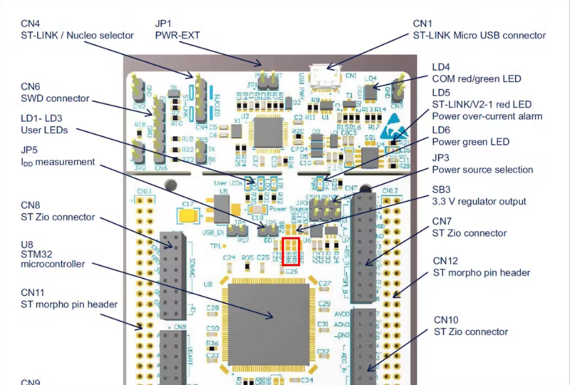
Wiznet W5300 Will work in the below listed Nucleo Boards
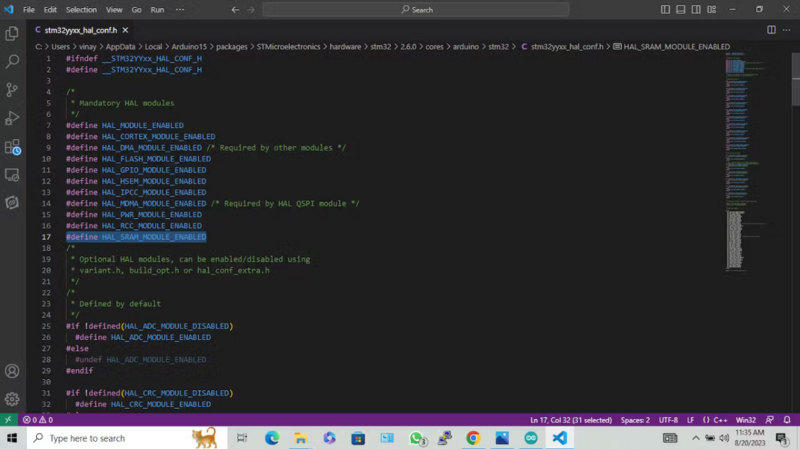
We need to Add [SRAM Enable] to the config file in order to make Wiznet W5300 Work with STM32F207 Using Arduino Libraries.
Open the stm32yyxx_hal_conf.h from the folderC:\Users\scarlet\AppData\Local\Arduino15\packages\STMicroelectronics\hardware\stm32\2.0.0\cores\arduino\stm32\stm32yyxx_hal_conf.h
Add The Below line to the Code(Refer to the below-highlighted line to place )#define HAL_SRAM_MODULE_ENABLED
Remove the existing FMC directory.
C:\Users_YOUR_NAME_\AppData\Local\Arduino15\libraries\FMC
Remove the existing FMC init code.
C:\Users_YOUR_NAME_\AppData\Local\Arduino15\libraries\Ethernet\w5100.cpp
FMC.init(); => //FMC.init();
successfully completed all the necessary configurations to enable the STM32F207 (NUCLEO-F207ZG) development board to operate seamlessly within the Arduino IDE environment. With this setup, we can now engage in advanced technical development, firmware programming, and deployment on the STM32F207 platform using the Arduino framework.
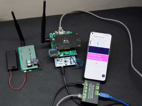
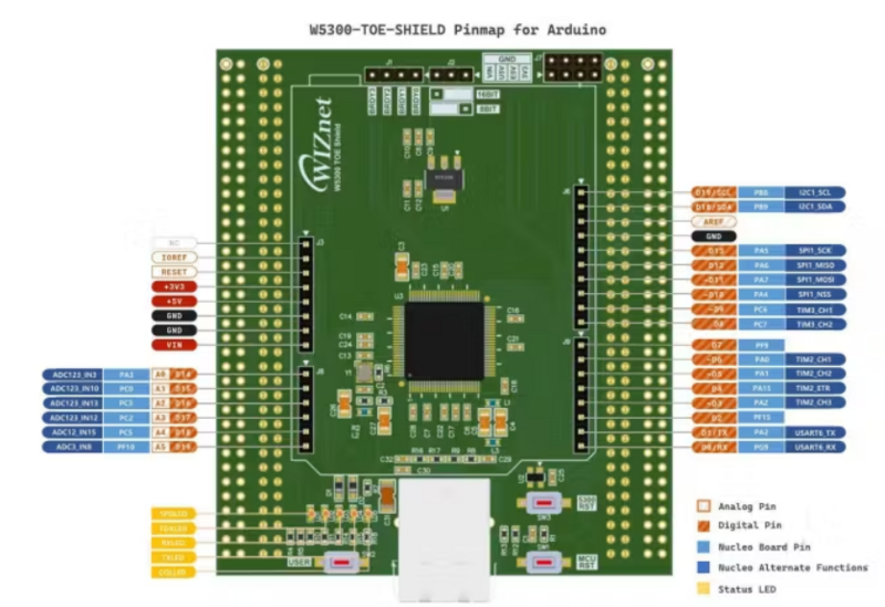
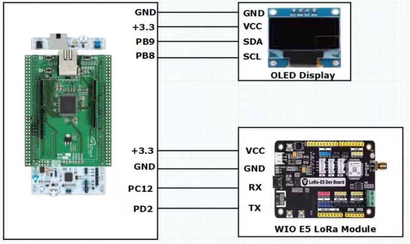
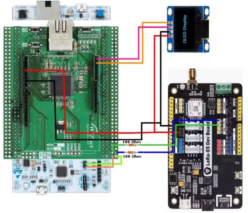
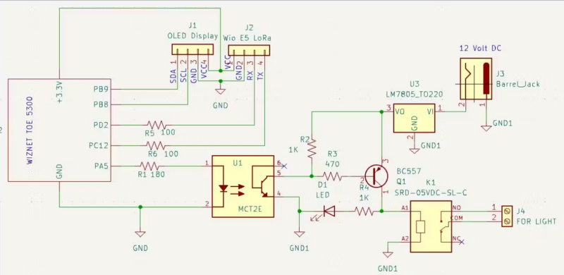
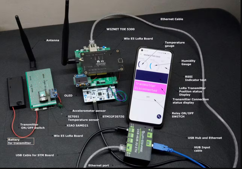
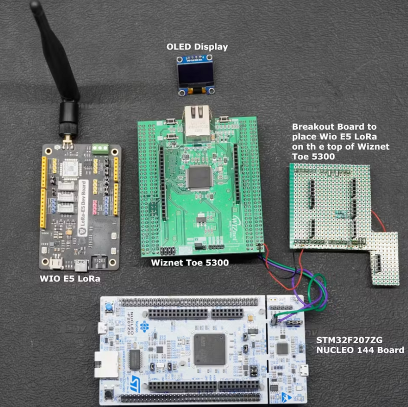
In this project, I demonstrate the utilization of STM32F207 and STM32F429-based Nucleo Boards in conjunction with the Wiznet ToE 5300 Ethernet shield. since both boards' pin configurations are the same there are no changes in the Circuit diagram or In the connection diagram.
Code For using STM32F207 (NUCLEO-F207ZG) development board in the project.#define BLYNK_PRINT Serial // Enables Serial Monitor
/* Fill in information from Blynk Device Info here */
#define BLYNK_TEMPLATE_ID "XXXXXXXX"
#define BLYNK_TEMPLATE_NAME "WIZNET TOE 5300"
#define BLYNK_AUTH_TOKEN "XXXXXXXXXXXXXXXXXXXXXXXXXXXXXX"
#include <Arduino.h>
#include "Ethernet.h"
#include "HardwareSerial.h"
#include <BlynkSimpleEthernet.h>
#include "stm32f2xx_hal_sram.h"
#include <Wire.h>
#include <Adafruit_GFX.h>
#include <Adafruit_SSD1306.h>
#define W5x00_INT_Pin GPIO_PIN_8
#define W5x00_INT_GPIO_Port GPIOC
#define W5x00_RST_Pin GPIO_PIN_9
#define W5x00_RST_GPIO_Port GPIOC
#define SCREEN_WIDTH 128 // OLED display width, in pixels
#define SCREEN_HEIGHT 64 // OLED display height, in pixels
#define OLED_RESET 4 // Reset pin # (or -1 if sharing Arduino reset pin)
Adafruit_SSD1306 display(SCREEN_WIDTH, SCREEN_HEIGHT, &Wire, OLED_RESET);
/* Network Info */
#define SERVER_PORT 5000
#define MAX_CLIENT 8
int Relay = PA5;
int humidity;
HardwareSerial Serial5(UART5);
EthernetServer server(SERVER_PORT);
EthernetClient clients[MAX_CLIENT];
static char recv_buf[512];
static bool is_exist = false;
BlynkTimer timer;
WidgetLCD lcd(V4);
WidgetLCD lcd2(V5);
byte mac[] = { 0xDE, 0xAD, 0xBE, 0xEF, 0xFE, 0xED};
IPAddress ip(192, 168, 137, 111);
IPAddress myDns(8, 8, 8, 8);
IPAddress gateway(192, 168, 137, 1);
IPAddress subnet(255, 255, 255, 0);
static void HAL_FSMC_MspInit(void){
GPIO_InitTypeDef GPIO_InitStruct ={0};
__HAL_RCC_GPIOD_CLK_ENABLE();
__HAL_RCC_GPIOE_CLK_ENABLE();
__HAL_RCC_GPIOF_CLK_ENABLE();
GPIO_InitStruct.Pin = GPIO_PIN_0|GPIO_PIN_1|GPIO_PIN_2|GPIO_PIN_3
|GPIO_PIN_4|GPIO_PIN_5|GPIO_PIN_12|GPIO_PIN_13
|GPIO_PIN_14|GPIO_PIN_15;
GPIO_InitStruct.Mode = GPIO_MODE_AF_PP;
GPIO_InitStruct.Pull = GPIO_NOPULL;
GPIO_InitStruct.Speed = GPIO_SPEED_FREQ_VERY_HIGH;
GPIO_InitStruct.Alternate = GPIO_AF12_FSMC;
HAL_GPIO_Init(GPIOF, &GPIO_InitStruct);
GPIO_InitStruct.Pin = GPIO_PIN_7|GPIO_PIN_8|GPIO_PIN_9|GPIO_PIN_10
|GPIO_PIN_11|GPIO_PIN_12|GPIO_PIN_13|GPIO_PIN_14
|GPIO_PIN_15;
GPIO_InitStruct.Mode = GPIO_MODE_AF_PP;
GPIO_InitStruct.Pull = GPIO_NOPULL;
GPIO_InitStruct.Speed = GPIO_SPEED_FREQ_VERY_HIGH;
GPIO_InitStruct.Alternate = GPIO_AF12_FSMC;
HAL_GPIO_Init(GPIOE, &GPIO_InitStruct);
GPIO_InitStruct.Pin = GPIO_PIN_8|GPIO_PIN_9|GPIO_PIN_10|GPIO_PIN_14
|GPIO_PIN_15|GPIO_PIN_0|GPIO_PIN_1|GPIO_PIN_4
|GPIO_PIN_5|GPIO_PIN_7;
GPIO_InitStruct.Mode = GPIO_MODE_AF_PP;
GPIO_InitStruct.Pull = GPIO_NOPULL;
GPIO_InitStruct.Speed = GPIO_SPEED_FREQ_VERY_HIGH;
GPIO_InitStruct.Alternate = GPIO_AF12_FSMC;
HAL_GPIO_Init(GPIOD, &GPIO_InitStruct);
}
static void MX_FSMC_Init(void)
{
FSMC_NORSRAM_TimingTypeDef Timing = {0};
SRAM_HandleTypeDef hsram1;
__HAL_RCC_FSMC_CLK_ENABLE();
hsram1.Instance = FSMC_NORSRAM_DEVICE;
hsram1.Extended = FSMC_NORSRAM_EXTENDED_DEVICE;
/* hsram1.Init */
hsram1.Init.NSBank = FSMC_NORSRAM_BANK1;
hsram1.Init.DataAddressMux = FSMC_DATA_ADDRESS_MUX_DISABLE;
hsram1.Init.MemoryType = FSMC_MEMORY_TYPE_SRAM;
hsram1.Init.MemoryDataWidth = FSMC_NORSRAM_MEM_BUS_WIDTH_16;
hsram1.Init.BurstAccessMode = FSMC_BURST_ACCESS_MODE_DISABLE;
hsram1.Init.WaitSignalPolarity = FSMC_WAIT_SIGNAL_POLARITY_LOW;
hsram1.Init.WrapMode = FSMC_WRAP_MODE_DISABLE;
hsram1.Init.WaitSignalActive = FSMC_WAIT_TIMING_BEFORE_WS;
hsram1.Init.WriteOperation = FSMC_WRITE_OPERATION_ENABLE;
hsram1.Init.WaitSignal = FSMC_WAIT_SIGNAL_DISABLE;
hsram1.Init.ExtendedMode = FSMC_EXTENDED_MODE_DISABLE;
hsram1.Init.AsynchronousWait = FSMC_ASYNCHRONOUS_WAIT_DISABLE;
hsram1.Init.WriteBurst = FSMC_WRITE_BURST_DISABLE;
/* Timing */
Timing.AddressSetupTime = 1;
Timing.AddressHoldTime = 1;
Timing.DataSetupTime = 4;
Timing.BusTurnAroundDuration = 0;
Timing.CLKDivision = 2;
Timing.DataLatency = 2;
Timing.AccessMode = FSMC_ACCESS_MODE_A;
if (HAL_SRAM_Init(&hsram1, &Timing, NULL) != HAL_OK)
{
Error_Handler();
}
}
static int at_send_check_response(char *p_ack, int timeout_ms, char *p_cmd, ...)
{
int ch = 0;
int index = 0;
int startMillis = 0;
va_list args;
memset(recv_buf, 0, sizeof(recv_buf));
va_start(args, p_cmd);
Serial5.printf(p_cmd, args);
Serial.printf(p_cmd, args);
va_end(args);
delay(200);
startMillis = millis();
if (p_ack == NULL)
{
return 0;
}
do
{
while (Serial5.available() > 0)
{
ch = Serial5.read();
recv_buf[index++] = ch;
Serial.print((char)ch);
delay(2);
}
if (strstr(recv_buf, p_ack) != NULL)
{
return 1;
}
}
while (millis() - startMillis < timeout_ms);
return 0;
}
////////////////////////////////////////////////////////////////////
static int recv_prase(void)
{
char ch;
int index = 0;
memset(recv_buf, 0, sizeof(recv_buf));
while (Serial5.available() > 0)
{
ch = Serial5.read();
recv_buf[index++] = ch;
Serial.print((char)ch);
delay(2);
}
if (index)
{
char *p_start = NULL;
char data[32] = {
0,
};
int rssi = 0;
int snr = 0;
p_start = strstr(recv_buf, "+TEST: RX \"5345454544");
if (p_start)
{
p_start = strstr(recv_buf, "5345454544");
if (p_start && (1 == sscanf(p_start, "5345454544%s,", data)))
{
display.clearDisplay();
display.setCursor(0,0);
display.print("Transmitter found");
display.display();
data[16] = 0;
int data1,data2,data3,data4;
char *endptr,*endptr1,*endpt2,*endptr3;
char dataarray1[5] = {data[0], data[1],data[2], data[3]};
char dataarray2[5] = {data[4], data[5], data[6], data[7]};
char dataarray3[5] = {data[8], data[9], data[10], data[11]};
char dataarray4[5] = {data[12], data[13],data[14], data[15]};
data1 = strtol(dataarray1, &endptr, 16);
data2 = strtol(dataarray2, &endptr1, 16);
data3 = strtol(dataarray3, &endptr, 16);
data4 = strtol(dataarray4, &endptr1, 16);
lcd2.clear();
Serial.print("data1:");
Serial.print(data1);
Serial.println();
Serial.print("data2:");
Serial.print(data2);
Serial.println();
Serial.print("data3:");
Serial.print(data3);
Serial.println();
Serial.print("data received displaying on the wio terminal");
Serial.print("\r\n");
Blynk.virtualWrite(V2,data1);
display.setCursor(0, 20);
display.print("Temperature:");
display.print(data1);
display.print(" C");
humidity = 0.5 * (data1 + 25);
Blynk.virtualWrite(V3,humidity);
display.setCursor(0, 30);
display.print("Humidity:");
display.print(humidity );
display.print("%");
if(data2 <=10)
{
display.setCursor(0,45);
display.print("The device Position had Changed");
lcd.clear(); //Use it to clear the LCD Widget
lcd.print(0, 0, "The device Posi"); // use: (position X: 0-15, position Y: 0-1, "Message you want to print")
lcd.print(0, 1, "tion had Changed"); // use: (position X: 0-15, position Y: 0-1, "Message you want to print")
}
else
{
display.setCursor(0,45);
display.print("The device is in a constant position");
lcd.clear(); //Use it to clear the LCD Widget
lcd.print(0, 0, "The device is in"); // use: (position X: 0-15, position Y: 0-1, "Message you want to print")
lcd.print(0, 1, "constant position"); // use: (position X: 0-15, position Y: 0-1, "Message you want to print")
}
}
p_start = strstr(recv_buf, "RSSI:");
if (p_start && (1 == sscanf(p_start, "RSSI:%d,", &rssi)))
{
String newrssi = String(rssi);
Serial.print(rssi);
Serial.print("\r\n");
Blynk.virtualWrite(V6,newrssi);
display.setCursor(0,10);
display.print("RSSI:");
display.print(rssi);
display.print(" dB");
display.display();
}
p_start = strstr(recv_buf, "SNR:");
if (p_start && (1 == sscanf(p_start, "SNR:%d", &snr)))
{
Serial.print(snr);
Serial.print("\r\n");
}
return 1;
}
}
return 0;
}
/////////////////////////////////////////////////////////////////////////////
static int node_recv(uint32_t timeout_ms)
{
at_send_check_response("+TEST: RXLRPKT", 1000, "AT+TEST=RXLRPKT\r\n");
int startMillis = millis();
do
{
if (recv_prase())
{
return 1;
}
}
while (millis() - startMillis < timeout_ms);
Serial.print("Transmitter Not Found");
Serial.println("");
display.clearDisplay();
display.setCursor(0,0);
display.print("Transmitter Not Found");
display.display();
lcd.clear();
lcd2.clear(); //Use it to clear the LCD Widget
lcd2.print(0, 0, "Transmitter"); // use: (position X: 0-15, position Y: 0-1, "Message you want to print")
lcd2.print(0, 1, "Disconnected"); // use: (position X: 0-15, position Y: 0-1, "Message you want to print")
display.clearDisplay();
return 0;
}
////////////////////////////
BLYNK_WRITE(V0)
{
int x = param.asInt();
Serial.println(x);
if(x == 1)
{
digitalWrite(Relay,HIGH);
display.clearDisplay();
display.setCursor(0,20);
display.print("LED ON");
display.display();
}
else
{
digitalWrite(Relay,LOW);
display.clearDisplay();
display.setCursor(0,20);
display.print("LED OFF");
display.display();
}}
void setup() {
MX_FSMC_Init();
HAL_FSMC_MspInit();
Serial3.setRx(PC11);
Serial3.setTx(PC10);
Serial3.begin(9600);
Serial5.begin(9600);
pinMode(Relay,OUTPUT);
Ethernet.begin(mac, ip, myDns, gateway, subnet);
Blynk.begin(BLYNK_AUTH_TOKEN);
if(!display.begin(SSD1306_SWITCHCAPVCC, 0x3C))
{
Serial.println(F("SSD1306 allocation failed"));
for(;;);
}
display.display();
delay(2000); // Pause for 2 seconds
if (at_send_check_response("+AT: OK", 100, "AT\r\n"))
{
is_exist = true;
at_send_check_response("+MODE: TEST", 1000, "AT+MODE=TEST\r\n");
at_send_check_response("+TEST: RFCFG", 1000, "AT+TEST=RFCFG,866,SF12,125,12,15,14,ON,OFF,OFF\r\n");
delay(200);
}
else
{
is_exist = false;
Serial.print("No Serial5 module found.\r\n");
display.setTextSize(1); // Normal 1:1 pixel scale
display.setTextColor(SSD1306_WHITE); // Draw white text
display.setCursor(0,0); // Start at top-left corner
display.println(F("LoRa Device Not Found"));
display.display();
}
display.clearDisplay();
display.setTextSize(1); // Normal 1:1 pixel scale
display.setTextColor(SSD1306_WHITE); // Draw white text
display.setCursor(0,0); // Start at top-left corner
display.print("IP:");
display.print(ip);
display.display();
delay(1000);
display.clearDisplay();
}
void loop() {
display.clearDisplay();
if (is_exist)
{
node_recv(2000);
}
timer.run();
Blynk.run();
}


 Français
 English
 Deutsch
 Español
 Italiano
 Português