In this tutorial you ll learn how to build you own DIY electromagnetic interference detector.
You ll understand what EMI is, and why it’s important to be aware of it.

Difficulté
Facile
Durée
1 jour(s)
Catégories
Électronique
Coût
1 USD ($)
Introduction
EMI is a form of electromagnetic radiation: a combination of electric and magnetic waves traveling outward from anywhere that an electrical power signal is changing or being turned on and off rapidly
Where this gadget excels is spotting “phantom” or “vampire” energy loads.
More correctly called standby power, this is the amount of electricity that constantly flows through some electronic devices, even when they’re supposedly switched off or in standby mode. Devices use standby power on features such as digital clocks, remote control reception, and thermometers.
Relatively weak energy efficiency regulations in the United States result in many devices drawing far more wattage than they need in standby mode.
the EMI detector works by capturing the electrical energy coming into the arduino's analog port, and turning it into a sound via the speaker.
Matériaux
Outils
Étape 1 - Building the EMI detector
The EMI detector comes in two forms: the gadget is mounted on a shield suitable for an arduino uno board, or the detector is embedded on a shield on which an arduino nano is mounted.
We will start by building the shield for arduino uno
here s the wiring diagram for the EMI detector
Step by step instructions for the Arduino Uno shield
First, solder at least a couple of pins to the PCB. These will go into GND and Analog 5 in th arduino uno board.
Next, solder an extra pin on the opposite side of the PCB. This will connect to Digital 9 on the arduino board.
The speaker will also be soldered onto the PCB. Solder the positive end of the speaker to the pin which goes into analog 9 on the arduino.
Solder the negative end of the speaker into the PCB.
Then connect a short (5 cm max) piece of electric wire to the negative end of the speaker. The other end of the cable is soldered on the pin which goes into GND.
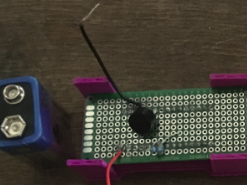
Use a 1Mohm resistor to connect the pin which goes into GND and the one that goes into Analog 5 on the PCB (see photo above).
It’s now time to add the antenna of your EMI detector.
Take about 20 cm of solid core wire, and solder one end of it on to the PCB, precisely to the pin that goes into Analog 5 on the board.
Step by step instructions for the Arduino Nano shield
An timelapse is available here
Solder two strips of female headers onto a PCB (3cm x 7cm)
You will need to be able to arrange the arduino nano onto these strips of female headers.
Solder the positive side of the speaker to the PCB, in correspondence with the D3 pin. Solder the other end of the speaker onto the PCB, in correspondence with GND pin of the arduino nano.
Next, grab the 1Mohm resistor, and solder one end to the PCB pin which leads to A5 on the board, the other end to the PCB pin which goes into GND.
To make the antenna of your device, take a piece of solid core wire (about 15 cm long), and solder one end of it to the PCB pin which leads to GND on the arduino nano.
Finally, grap two short pieces of electric wire. You will use them to connect a 9V battery to the arduino nano and power the board. Solder one end of the first cable to VIN on the arduino nano, solder one end of the other cable to GND.


Étape 2 - Building the EMI detector 2


Étape 3 - Building the EMI detector 3

Étape 4 - Place the EMI detector inside its case
You can download the stl file and 3D print the case. The stl file is available here.


Étape 5 - Program the arduino board
Whether you re using an arduino uno or a nano, the code that you ll need to upload in order for the probe to function correctly is basically the same.
Just make sure to program the correct digital pin for the piezo speaker. In the instructions above, we connected the speaker on D9 on an arduino uno, and D3 on an arduino nano.
// Arduino Electromagnetic interference detector
// Code modified by Patrick Di Justo, based on
// Aaron ALAI EMF Detector April 22nd 2009 VERSION 1.0
// aaronalai1@gmail.com
//
// This outputs sound and numeric data to the 4char
#include <SoftwareSerial.h>
#define SerialIn 2
#define SerialOut 7
#define wDelay 900
int inPin = 5;
int val = 0;
SoftwareSerial mySerialPort(SerialIn, SerialOut);
void setup()
{
pinMode(SerialOut, OUTPUT);
pinMode(SerialIn, INPUT);
mySerialPort.begin(19200);
mySerialPort.print("vv");
mySerialPort.print("xxxx");
delay(wDelay);
mySerialPort.print("----");
delay(wDelay);
mySerialPort.print("8888");
delay(wDelay);
mySerialPort.print("xxxx");
delay(wDelay);
Serial.begin(9600);
}
void loop()
{
val = analogRead(inPin);
Serial.println(val);
dispData(val);
val = map(val, 1, 100, 1, 2048);
tone(9,val,10);
}
void dispData(int i)
{
if ((i<-999)
Étape 6 - Activity Idea
You can use the EMI probe to compare and contrast EMI radiations deriving from different electronic appliances.
Hold the probe next to a stereo system or a TV whilst these devices are in standby mode, and you ll probably get a similar reading to a laptop when this is turned on.
Notes et références
List of parts:
1x 8ohm speaker
1x arduino uno board
1x 40x60 PCB
1x 1Mohm resistor
single core electric wire
male pin header strip for arduino
1x arduino uno or nano board
Draft
 Français
 English
 Deutsch
 Español
 Italiano
 Português