Introduction
In the previous two tutorials, we have seen how to get started with ESPNOW and how to transmit DHT11 sensor data via ESPNOW.
This tutorial will show how to control physical devices like LED, Relay, or other electrical & electronic applications.
Things that we need:
You need two ESP32 Dev boards, that's all. ESP32 Dev boards have already been equipped with an onboard LED. So, we can just try to control them via ESPNOW. Also, you can add an external LED to the digital pins, and we can control them.
Matériaux
Outils
Étape 1 - Get PCBs for Your Projects Manufactured
You must check out PCBWAY for ordering PCBs online for cheap!
You get 10 good-quality PCBs manufactured and shipped to your doorstep for cheap. You will also get a discount on shipping on your first order. Upload your Gerber files onto PCBWAY to get them manufactured with good quality and quick turnaround time. PCBWay now could provide a complete product solution, from design to enclosure production. Check out their online Gerber viewer function. With reward points, you can get free stuff from their gift shop.
Étape 2 - Transmitter Node Setup
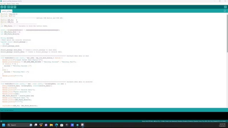
First, we need to build our controller. We already know how to get the MAC address of our receiver node. Use the sketch below to get the MAC Address of the receiver.#include "WiFi.h"
void setup(){
Serial.begin(115200);
WiFi.mode(WIFI_MODE_STA);
Serial.println(WiFi.macAddress());
}
void loop(){
}#include <esp_now.h>
#include <WiFi.h>
//----------------------------------------Defines PIN Button and PIN LED.
#define LED_Pin 4
#define BTN_Pin 15
//----------------------------------------
int BTN_State; //--> Variable to hold the button state.
uint8_t broadcastAddress[] = {xxxxxxxxxxxxxxxxxxxxxxxxxxxxxxxxxxxxx};
int LED_State_Send = 0;
int LED_State_Receive;
String success;
//Must match the receiver structure
typedef struct struct_message {
int led;
} struct_message_send;
struct_message send_Data; // Create a struct_message to send data.
struct_message receive_Data; // Create a struct_message to receive data.
//++++++++++++++++++++++++++++++++++++++++++++++++++++++++++++++++++++++++++ Callback when data is sent
void OnDataSent(const uint8_t *mac_addr, esp_now_send_status_t status) {
Serial.print("\r\nLast Packet Send Status:\t");
Serial.println(status == ESP_NOW_SEND_SUCCESS ? "Delivery Success" : "Delivery Fail");
if (status ==0){
success = "Delivery Success :)";
}
else{
success = "Delivery Fail :(";
}
Serial.println(">>>>>");
}
//++++++++++++++++++++++++++++++++++++++++++++++++++++++++++++++++++++++++++ Callback when data is received
void OnDataRecv(const uint8_t * mac, const uint8_t *incomingData, int len) {
memcpy(&receive_Data, incomingData, sizeof(receive_Data));
Serial.println();
Serial.println("<<<<< Receive Data:");
Serial.print("Bytes received: ");
Serial.println(len);
LED_State_Receive = receive_Data.led;
Serial.print("Receive Data: ");
Serial.println(LED_State_Receive);
Serial.println("<<<<<");
digitalWrite(LED_Pin, LED_State_Receive);
}
//+++++++++++++++++++++++++++++++++++++++++++++++++++++++++++++++++++++++
void setup() {
Serial.begin(115200);
pinMode(LED_Pin, OUTPUT);
pinMode(BTN_Pin, INPUT);
WiFi.mode(WIFI_STA); //--> Set device as a Wi-Fi Station
//----------------------------------------Init ESP-NOW
if (esp_now_init() != ESP_OK) {
Serial.println("Error initializing ESP-NOW");
return;
}
//--------------------------------------
// get the status of Trasnmitted packet
esp_now_register_send_cb(OnDataSent);
//----------------------------------------Register peer
esp_now_peer_info_t peerInfo;
memcpy(peerInfo.peer_addr, broadcastAddress, 6);
peerInfo.channel = 0;
peerInfo.encrypt = false
//----------------------------------------Add peer
if (esp_now_add_peer(&peerInfo) != ESP_OK){
Serial.println("Failed to add peer");
return;
}
//----------------------------------------
esp_now_register_recv_cb(OnDataRecv); //--> Register for a callback function that will be called when data is received
}
//++++++++++++++++++++++++++++++++++++++++++++++++++++++++++++++++++++++++++
void loop() {
BTN_State = digitalRead(BTN_Pin); //--> Reads and holds button states.
//----------------------------------------When the button is pressed it will send data to control the LED on the ESP32 Target.
if(BTN_State == 1) {
LED_State_Send = !LED_State_Send;
send_Data.led = LED_State_Send;
Serial.println();
Serial.print(">>>>> ");
Serial.println("Send data");
//----------------------------------------Send message via ESP-NOW
esp_err_t result = esp_now_send(broadcastAddress, (uint8_t *) &send_Data, sizeof(send_Data));
if (result == ESP_OK) {
Serial.println("Sent with success");
}
else {
Serial.println("Error sending the data");
}
//----------------------------------------Wait for the button to be released. Release the button first to send the next data.
while(BTN_State == 1) {
BTN_State = digitalRead(BTN_Pin);
delay(10);
}
}
}
Étape 3 - Receiver Node Setup
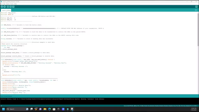
We have already built our transmitter; next, we need to set up our receiver node. Just upload the below Arduino sketch to build a receiver to get data from the transmitter and based on the input data it will glow the led.#include <esp_now.h>
#include <WiFi.h>
//----------------------------------------Defines PIN Button and PIN LED.
#define LED_Pin 4
#define BTN_Pin 15
//----------------------------------------
int BTN_State; //--> Variable to hold the button state.
uint8_t broadcastAddress[] = {xxxxxxxxxxxxxxxxxxxxxxxxxxxxxxxxxxxxxxxxxx}; //--> REPLACE WITH THE MAC Address of your transmitter. ESP32 A
int LED_State_Send = 0; //--> Variable to hold the data to be transmitted to control the LEDs on the paired ESP32.
int LED_State_Receive; //--> Variable to receive data to control the LEDs on the ESP32 running this code.
String success; //--> Variable to store if sending data was successful
//----------------------------------------Structure example to send data
//Must match the receiver structure
typedef struct struct_message {
int led;
} struct_message_send;
struct_message send_Data; // Create a struct_message to send data.
struct_message receive_Data; // Create a struct_message to receive data.
//----------------------------------------
void OnDataSent(const uint8_t *mac_addr, esp_now_send_status_t status) {
Serial.print("\r\nLast Packet Send Status:\t");
Serial.println(status == ESP_NOW_SEND_SUCCESS ? "Delivery Success" : "Delivery Fail");
if (status ==0){
success = "Delivery Success :)";
}
else{
success = "Delivery Fail :(";
}
Serial.println(">>>>>");
}
//++++++++++++++++++++++++++++++++++++++++++++++++++++++++++++++++++++++++++
void OnDataRecv(const uint8_t * mac, const uint8_t *incomingData, int len) {
memcpy(&receive_Data, incomingData, sizeof(receive_Data));
Serial.println();
Serial.println("<<<<< Receive Data:");
Serial.print("Bytes received: ");
Serial.println(len);
LED_State_Receive = receive_Data.led;
Serial.print("Receive Data: ");
Serial.println(LED_State_Receive);
Serial.println("<<<<<");
digitalWrite(LED_Pin, LED_State_Receive);
}
//++++++++++++++++++++++++++++++++++++++++++++++++++++++++++++++++++++++++++
void setup() {
Serial.begin(115200);
pinMode(LED_Pin, OUTPUT);
pinMode(BTN_Pin, INPUT);
WiFi.mode(WIFI_STA); //--> Set device as a Wi-Fi Station
if (esp_now_init() != ESP_OK) {
Serial.println("Error initializing ESP-NOW");
return;
}
//----------------------------------------
// get the status of Trasnmitted packet
esp_now_register_send_cb(OnDataSent);
//----------------------------------------
esp_now_peer_info_t peerInfo;
memcpy(peerInfo.peer_addr, broadcastAddress, 6);
peerInfo.channel = 0;
peerInfo.encrypt = false;
//----------------------------------------
//----------------------------------------Add peer
if (esp_now_add_peer(&peerInfo) != ESP_OK){
Serial.println("Failed to add peer");
return;
}
//----------------------------------------
}
void loop() {
BTN_State = digitalRead(BTN_Pin); //--> Reads and holds button states.
//----------------------------------------When the button is pressed it will send data to control the LED on the ESP32 Target.
if(BTN_State == 1) {
LED_State_Send = !LED_State_Send;
send_Data.led = LED_State_Send;
Serial.println();
Serial.print(">>>>> ");
Serial.println("Send data");
//----------------------------------------Send message via ESP-NOW
esp_err_t result = esp_now_send(broadcastAddress, (uint8_t *) &send_Data, sizeof(send_Data));
if (result == ESP_OK) {
Serial.println("Sent with success");
}
else {
Serial.println("Error sending the data");
}
//----------------------------------------
while(BTN_State == 1) {
BTN_State = digitalRead(BTN_Pin);
delay(10);
}
}
Étape 4 - Output Data
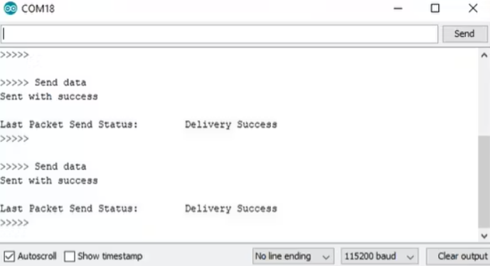
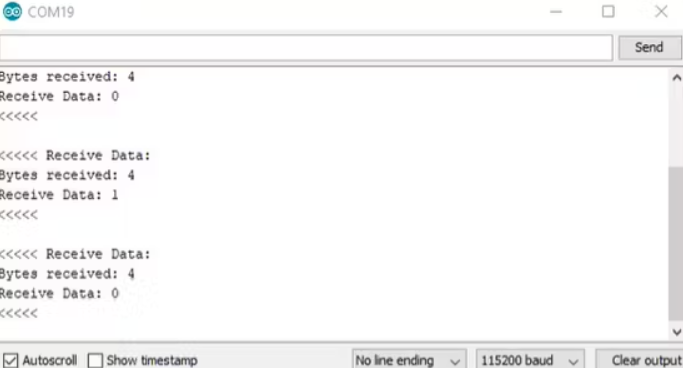
Here is the serial monitor data from the transmitter, once you press the transmitter button it will send the command to the receiver node. If it is received by the receiver it will mark as a success.
Here is the serial monitor data from the receiver, once the command from the transmitter is received by the receiver it will show the data and start to glow the led.
Étape 5 - Wrap-Up
In final words, now we know how to transmit the sensor data also how to control the appliances. Based on these we can easily build a home automation system. In upcoming tutorials, will see how to build a home automation system with ESONOW.
Published

 Français
 English
 Deutsch
 Español
 Italiano
 Português