Étape 1 - Preparation of the TEPEE squared tubes
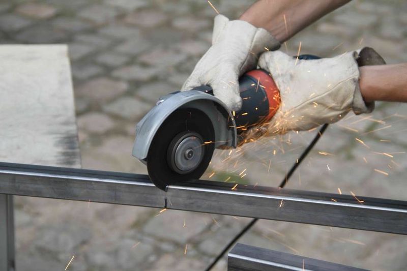
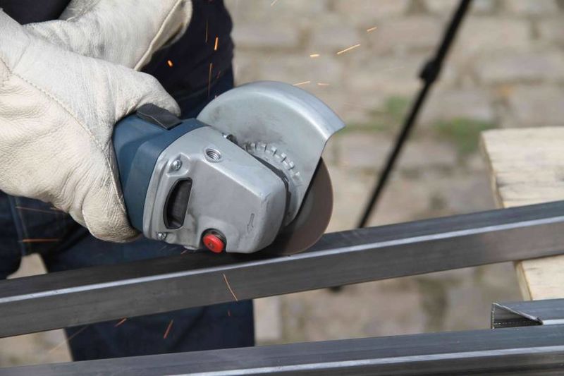
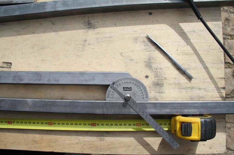
Cut at a length of 2300 mm 4 square tubes: a right cut and a 45° cut.
Drill the holes according to the 3D model in order to assemble the legs of the “tepee” (1 hole/square tube), the receiver’s fixation (1 hole/square tube), the fixation of the inferior square tube across the length (2 holes/square tube), the fixation of the transversal flat (1 hole/ square tube, 800mm from the bottom, measured at the furthest point of the 45° cut). Check the total length of the square tube: the length necessary to drill the holes is measured from the bottom of the leg.
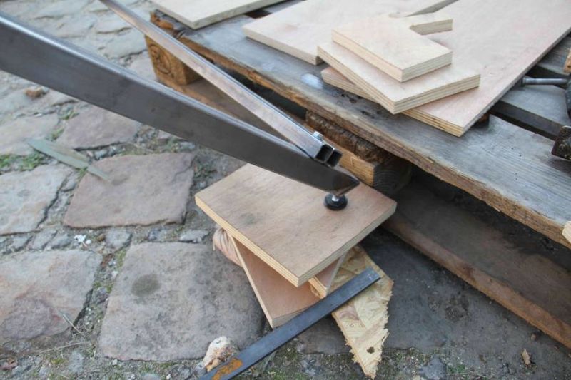
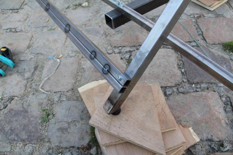
Cut 4 flats with 30 mm large, 40 mm long and 5 mm thick and check the dimensions. Drill and tap the flats at 10 mm from the edges to fix an adjustable leg made of a screw with a diameter of 8 mm. Weld the flats on the edges cut at 45°. By doing this, an adjustable horizontal leg is obtained.
Étape 2 - Preparation of the inferior square tubes and the reinforcement, the transversal flat
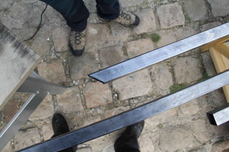
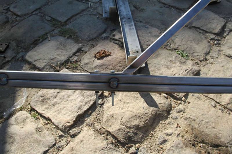
Cut the inferior square tubes: 4 square tubes 20x20x2200 mm. Possible improvements with rectangular tubes 20x30 or 20x40 mm. Weld two square tubes one next to each other in order to form a rectangular tube. Drill them on the edges as described on the 3D model.
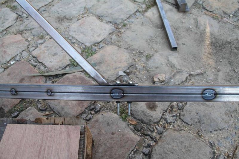
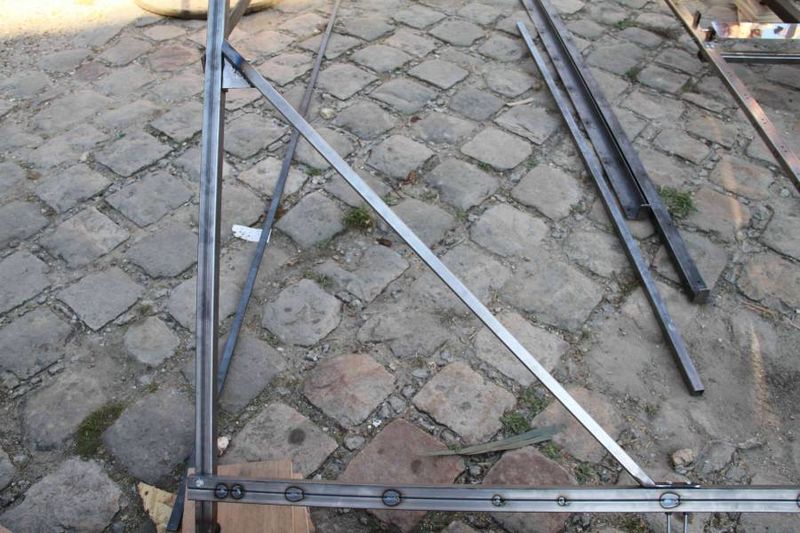
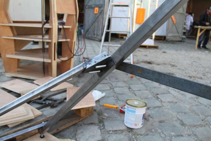
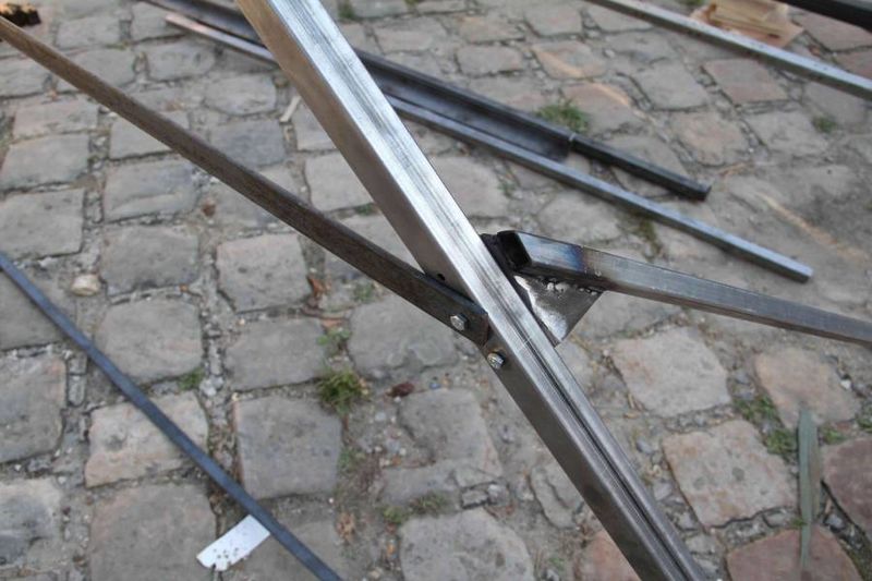
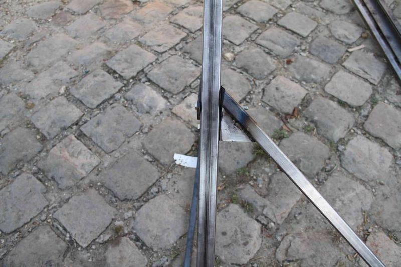
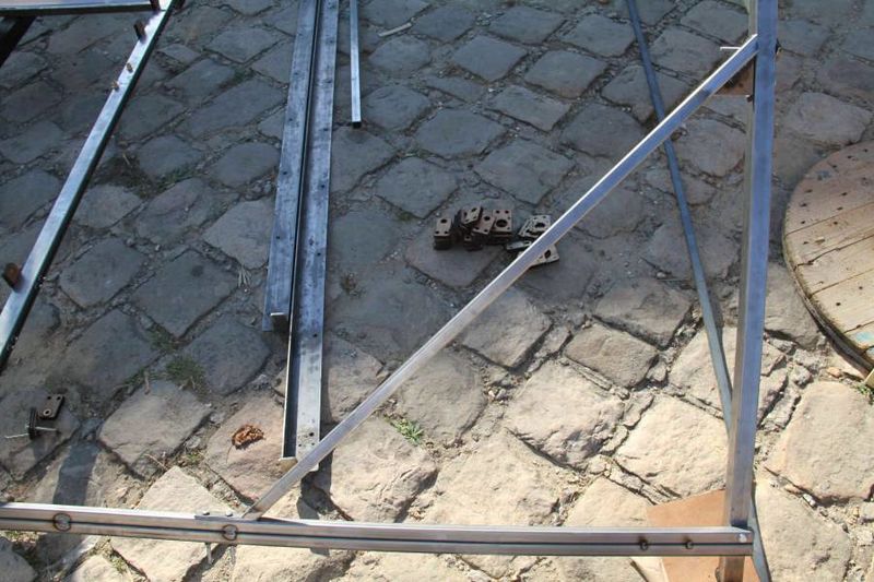
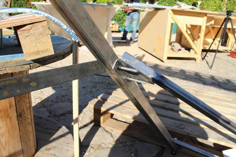
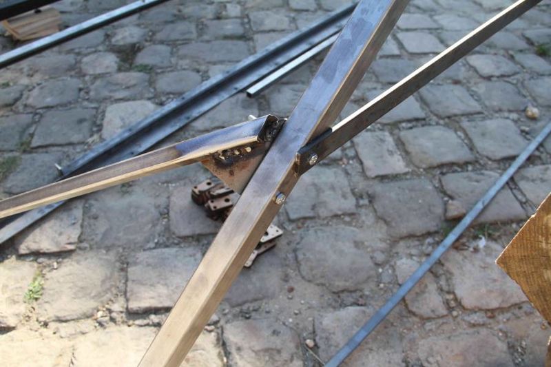
Cut the reinforcement square tubes: 2 square tubes 20x20x1000 mm with a 45° angle on the extremities. Cut two flats 20x3 mm, having a length of 100 mm and 2 steel angles (L shaped) 30x60 mm, having a length of 100 mm. Drill the four pieces according to the photos/3D model. Weld the steel angle and the flats at both extremities of the 1000 mm square tube in order to finish the reinforcement tubes. Check that there is an angle of 45° between the exterior surface of the flat and the square tube, as well between the exterior surface of the steel angle and the square tube. In this way, the right angle is warranted between the “tepee” square tube and the inferior square tube.
Cut the transversal flat: a flat of 30x5 mm having a length of 2150 mm. Drill it at the extremities according to the 3D model: the distance between the holes is 2120 mm (at 1500 mm from the hole of the assemblage “tepee”).
Étape 3 - Preparation of the transversal cable
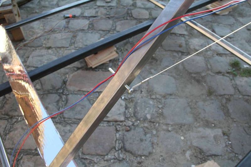
Cut approximatively a length of 2000 mm of the 2 mm diameter cable. Adjust its length in order to obtain a total length of 2120 mm between the fixation holes from the “tepee” squared tubes: make a loop at one edge and pinch the clamping ring on the cable. Measure the length of the adjustable element in an open position (Lmax) and cut the cable at a length of (2120 - Lmax + 40 mm) in order to form a loop at a final length of (2120 - Lmax).
Étape 4 - Assembling of the structure
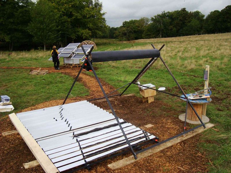
Assemble horizontally with a 10 diameter screw, two by two the square tubes to form the two “tepee” supports. Screw the adjustable legs on their support, located under the “tepee” squared tube.
Fix the inferior square tubes at the base of the tepee’s square tubes: the distance between the tepees is set. Position the 100 mm reinforcement square tubes with the clamps as can be seen in the photo. Check that: (1) the tepee square tube and the inferior square tube make a 90° angle, (2) the flat and the angle are parallel, as well the “tepee” square tube and the inferior square tube. Drill the “tepee” square tube and the inferior square tube through the hole situated on the reinforcement element (flat and angle). If the drill is not long enough, drill firstly the hole from the reinforcement element. Afterwards, mark the opposite point to the first hole and drill the second hole from the other side of the square tube.
2 persons lift the structure to form the tepee. A third person attaches the transversal flat with two screw in the north side, where are the reinforcements. Afterwards, he/she fixes the cable in the south side and he/she adjusts its length to 2120 mm. The structure should keep its balance, but it is better if someone holds the tepee from the south side. During this time, the other two persons can bring the receiver and position it on the tepee. This final step allows to keep the structure stable.

 Français
 English
 Deutsch
 Español
 Italiano
 Português