| Ligne 77 : | Ligne 77 : | ||
|Step_Title=Code | |Step_Title=Code | ||
|Step_Content=Voici le code à mettre dans le logiciel arduino. | |Step_Content=Voici le code à mettre dans le logiciel arduino. | ||
| + | |||
| + | <code> | ||
| + | #include "IRremote.h" | ||
| + | #include "Servo.h" | ||
| + | #undef round | ||
| + | |||
| + | //contrôle moteur | ||
| + | const int sensMotA=12; //moteur A (droit) Direction (High=sens 1 - Low=sens 2) | ||
| + | const int vitesseMotA=3; //moteur A (droit) PWM (Vitesse= 0 -255) | ||
| + | const int sensMotB=13; //moteur B (gauche) Direction (High=sens 1 - Low=sens 2) | ||
| + | const int vitesseMotB=11; //moteurr B (gauche) PWM (Vitesse= 0 -255) | ||
| + | |||
| + | //Pin Module récepteur IR et variable | ||
| + | int RECV_PIN = 5; | ||
| + | IRrecv irrecv(RECV_PIN); | ||
| + | decode_results results; | ||
| + | |||
| + | |||
| + | void setup() | ||
| + | { | ||
| + | |||
| + | //configurer tous les broches de commande du moteur en sortie | ||
| + | pinMode(sensMotA,OUTPUT); | ||
| + | pinMode(vitesseMotA,OUTPUT); | ||
| + | pinMode(sensMotB,OUTPUT); | ||
| + | pinMode(vitesseMotB,OUTPUT); | ||
| + | |||
| + | |||
| + | |||
| + | |||
| + | Serial.begin(9600); | ||
| + | |||
| + | //le récepteur IR | ||
| + | irrecv.enableIRIn(); | ||
| + | } | ||
| + | |||
| + | |||
| + | void loop() | ||
| + | { | ||
| + | Serial.println(results.value, DEC); | ||
| + | |||
| + | //IR signal reçu | ||
| + | if(irrecv.decode(&results)) | ||
| + | { | ||
| + | |||
| + | //avant | ||
| + | if(results.value==3031700205) | ||
| + | { | ||
| + | digitalWrite(sensMotA, HIGH); //Establishes forward direction of Channel A | ||
| + | analogWrite(vitesseMotA, 55); //Spins the motor on Channel B at half speed | ||
| + | digitalWrite(sensMotB, LOW); //Disengage the Brake for Channel B | ||
| + | analogWrite(vitesseMotB, 55); //Spins the motor on Channel B at half speed | ||
| + | } | ||
| + | //recule | ||
| + | else if(results.value==3031753245) | ||
| + | { | ||
| + | digitalWrite(sensMotA, LOW); //Establishes forward direction of Channel A | ||
| + | analogWrite(vitesseMotA, 255); //Spins the motor on Channel B at half speed | ||
| + | digitalWrite(sensMotB, HIGH); //Establishes forward direction of Channel A | ||
| + | analogWrite(vitesseMotB, 255); //Spins the motor on Channel B at half speed | ||
| + | //pivoter vers la gauche (PREVIOUS) | ||
| + | } | ||
| + | else if(results.value==3031718565) | ||
| + | { | ||
| + | digitalWrite(12, LOW); //Establishes forward direction of Channel A | ||
| + | analogWrite(3, 255); //Spins the motor on Channel B at half speed | ||
| + | digitalWrite(13, LOW); //Establishes forward direction of Channel A | ||
| + | analogWrite(11, 255); //Spins the motor on Channel B at half speed | ||
| + | |||
| + | //pivoter vers la droite (NEXT) | ||
| + | } | ||
| + | else if(results.value==3031734885) | ||
| + | { | ||
| + | digitalWrite(12, HIGH); //Establishes forward direction of Channel A | ||
| + | analogWrite(3, 255); //Spins the motor on Channel B at half speed | ||
| + | digitalWrite(13, HIGH); //Establishes forward direction of Channel A | ||
| + | analogWrite(11, 255); //Spins the motor on Channel B at half speed | ||
| + | } | ||
| + | //recevoir la prochaine valeur | ||
| + | irrecv.resume(); | ||
| + | |||
| + | //court délai d'attente pour répéter le signal IR | ||
| + | // (empêcher de s'arrêter si aucun signal reçu) | ||
| + | delay(150); | ||
| + | } | ||
| + | |||
| + | else | ||
| + | { | ||
| + | digitalWrite(sensMotA, LOW); //Spins the motor on Channel B at half speed | ||
| + | digitalWrite(vitesseMotA, LOW); //Spins the motor on Channel B at half speed | ||
| + | digitalWrite(sensMotB,LOW); //Spins the motor on Channel B at half speed}}} | ||
| + | digitalWrite(vitesseMotB, LOW); //Spins the motor on Channel B at half speed | ||
| + | |||
| + | } | ||
| + | } | ||
| + | </code> | ||
}} | }} | ||
{{Tuto Step | {{Tuto Step | ||
Version du 28 juin 2016 à 17:07
Matériaux
- 1x planche de bois épaisseur 5mm 610mm X 407mm
- 1x Arduino Uno
- 2x Moteurs DC
- 1x Motor Shield
- 1x capteur infrarouge
- 1x télécommande infrarouge (lecteur Dvd)
- 2x supports de pile (6 pile LR6 1,5Volt) (Alimentation principale Arduino Uno)
- 4x Piles 4,5Volts (2 pack montés en parallèle, chaque pack comporte 2 piles 4,5V montées en série) - (ça fait une alimentation sous 9V pour l’alimentation de puissance j’ai mis en parallèle pour avoir une plus longue autonomie)
- 8x Ecrous M4
- 8x vis M4 – 50
- 4x Embase M4
- 1x roue folle
Outils
Étape 1 - Plans
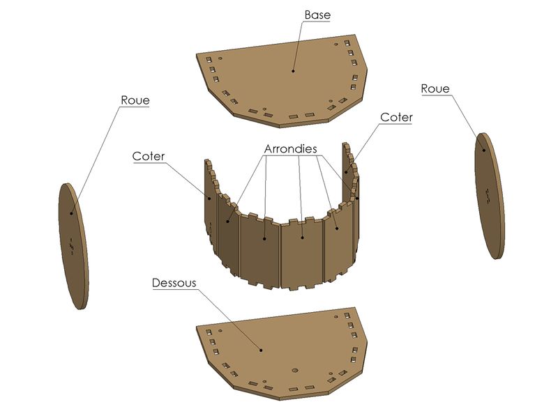
Voici les plans de chaque pièces pour faire le robot avec cotation ( en mm)
Téléchargement des fichiers : https://framadrive.org/index.php/s/oHlHOqSsc18I4U1
Étape 2 - Base
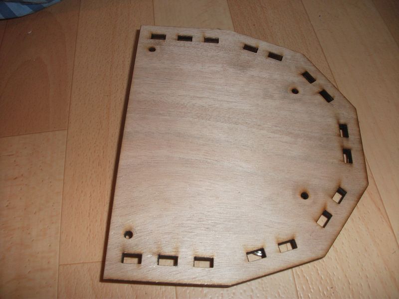
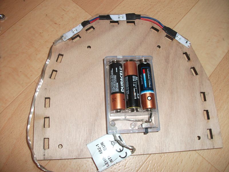
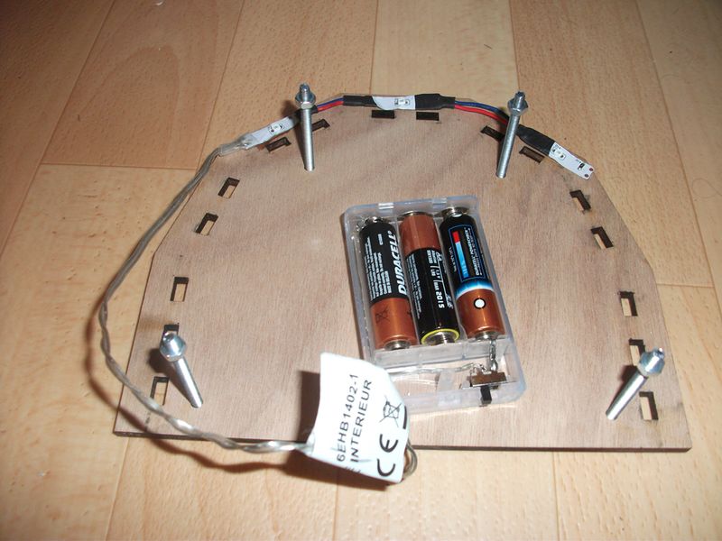
Commençons par prendre la base en ajoutant le support avec c’est pile relier au 3 LEDs vertes.
Prendre 4 vis M4 les insérer dans les 4 trous puis fixer 1 écrou sur chaque vis.
Étape 3 - Dessous
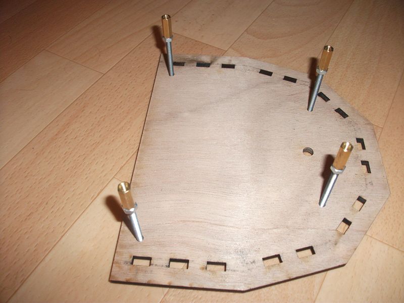
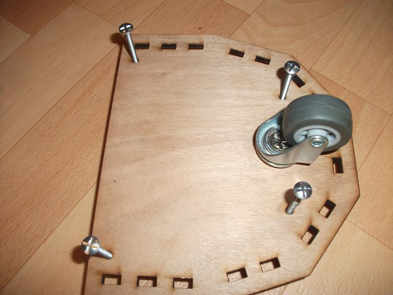
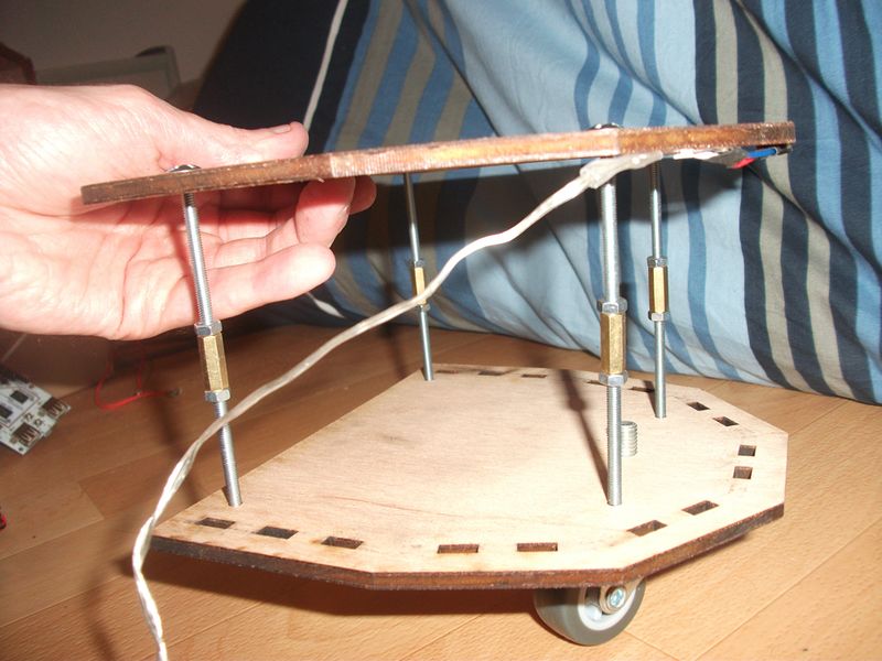
Insérer 4 vis M4 50mm avec leurs écrous et embase, puis retourner l’ensemble pour fixer la roue folle.
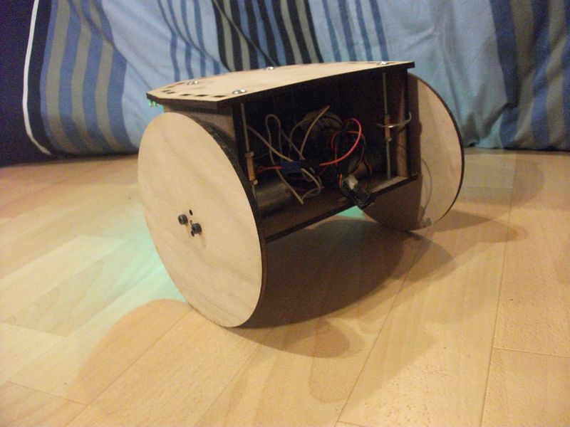
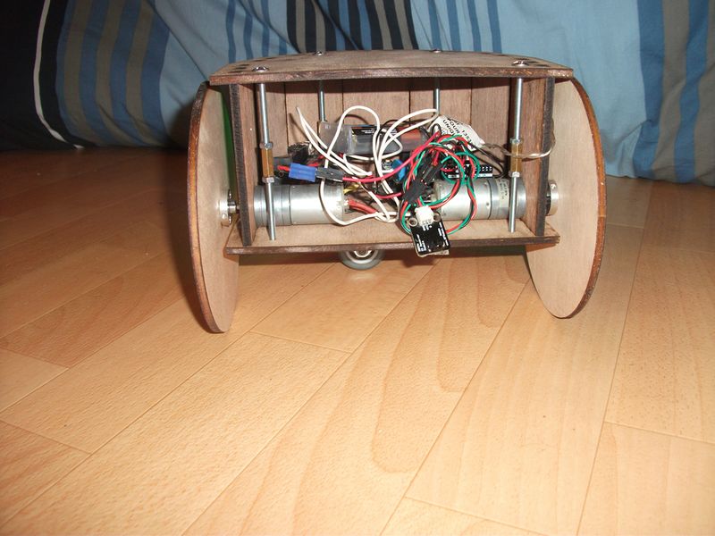
Étape 6 - Assemblage final
Assembler les arrondis ainsi que les cotés avec moteur sur l’illustration vu en étape 4.
Étape 8 - Code
Voici le code à mettre dans le logiciel arduino.
#include "IRremote.h"
- include "Servo.h"
- undef round
//contrôle moteur
const int sensMotA=12; //moteur A (droit) Direction (High=sens 1 - Low=sens 2)
const int vitesseMotA=3; //moteur A (droit) PWM (Vitesse= 0 -255)
const int sensMotB=13; //moteur B (gauche) Direction (High=sens 1 - Low=sens 2)
const int vitesseMotB=11; //moteurr B (gauche) PWM (Vitesse= 0 -255)
//Pin Module récepteur IR et variable
int RECV_PIN = 5;
IRrecv irrecv(RECV_PIN);
decode_results results;
void setup()
{
//configurer tous les broches de commande du moteur en sortie
pinMode(sensMotA,OUTPUT);
pinMode(vitesseMotA,OUTPUT);
pinMode(sensMotB,OUTPUT);
pinMode(vitesseMotB,OUTPUT);
Serial.begin(9600);
//le récepteur IR
irrecv.enableIRIn();
}
void loop()
{
Serial.println(results.value, DEC);
//IR signal reçu
if(irrecv.decode(&results))
{
//avant
if(results.value==3031700205)
{
digitalWrite(sensMotA, HIGH); //Establishes forward direction of Channel A
analogWrite(vitesseMotA, 55); //Spins the motor on Channel B at half speed
digitalWrite(sensMotB, LOW); //Disengage the Brake for Channel B
analogWrite(vitesseMotB, 55); //Spins the motor on Channel B at half speed
}
//recule
else if(results.value==3031753245)
{
digitalWrite(sensMotA, LOW); //Establishes forward direction of Channel A
analogWrite(vitesseMotA, 255); //Spins the motor on Channel B at half speed
digitalWrite(sensMotB, HIGH); //Establishes forward direction of Channel A
analogWrite(vitesseMotB, 255); //Spins the motor on Channel B at half speed
//pivoter vers la gauche (PREVIOUS)
}
else if(results.value==3031718565)
{
digitalWrite(12, LOW); //Establishes forward direction of Channel A
analogWrite(3, 255); //Spins the motor on Channel B at half speed
digitalWrite(13, LOW); //Establishes forward direction of Channel A
analogWrite(11, 255); //Spins the motor on Channel B at half speed
//pivoter vers la droite (NEXT)
}
else if(results.value==3031734885)
{
digitalWrite(12, HIGH); //Establishes forward direction of Channel A
analogWrite(3, 255); //Spins the motor on Channel B at half speed
digitalWrite(13, HIGH); //Establishes forward direction of Channel A
analogWrite(11, 255); //Spins the motor on Channel B at half speed
}
//recevoir la prochaine valeur
irrecv.resume();
//court délai d'attente pour répéter le signal IR
// (empêcher de s'arrêter si aucun signal reçu)
delay(150);
}
else
{
digitalWrite(sensMotA, LOW); //Spins the motor on Channel B at half speed
digitalWrite(vitesseMotA, LOW); //Spins the motor on Channel B at half speed
digitalWrite(sensMotB,LOW); //Spins the motor on Channel B at half speed
}
digitalWrite(vitesseMotB, LOW);    //Spins the motor on Channel B at half speed
}
}
}}
Étape 9 - Évolutions envisagées
Prochaine évolution mettre un capteur ultrason pour détection et évitement d’obstacle et un suiveur de ligne.
Cochez cette case si vous considérez ce tutoriel terminé
 Français
 English
 Deutsch
 Español
 Italiano
 Português