Sommaire
- 1 Introduction
- 2 Étape 1 - Cutting the square tubes
- 3 Étape 2 - Mark and drill the holes on the square tubes for the support (30x40 mm)
- 4 Étape 3 - Mark and drill the holes on the extremities of the main square tubes
- 5 Étape 4 - Assembling all the tubes
- 6 Étape 5 - Cut the wood support pieces for the motors and the axes of the mirror
- 7 Étape 6 - Fix the wood support pieces on the frame
- 8 Étape 7 - Assembling the two frames
- 9 Notes et références
- 10 Commentaires
Introduction
Matériaux
- 2 main square tubes 25x25 mm
- 2 square tubes for the support 30x40 mm (the mirrors are fixed on it)
- Square tubes for the support 30x40 mm, length of 1430 mm
- Wood board
- Laser cutter
- Square tube made of aluminum
- Stainless steel bar
- Wood board
- Mirror sheet
Outils
- Hack saw
- Grinder
- Drilling machine
- Bristol paper
- Printer/laser cutting
- Adhesive tape
Étape 1 - Cutting the square tubes
Use the grinder to cut at the length of 2130 mm the two main squared tubes and at the length of 1430 mm the 2 square tubes for the support.
Étape 2 - Mark and drill the holes on the square tubes for the support (30x40 mm)
Goal The two square tubes for the support have to be drilled with two holes every 143 mm. The position of the holes assures that the mirrors are parallel. It is important to work precisely so that the mirrors reflect the light in the same line.
How to? Print the template. Use the available drawing file which is composed of two parts; it is enough to put the two parts one next to each other. Put the template on the square tube and make sure that the paper is fixed to the edges and the extremities of the tube. Fix the template with the adhesive tape. Attention: if the square tube is welded from the interior on one face, this face has to be drilled first. Otherwise, if the opposite face is drilled, the drill will be deviated near the welding point.
Punch precisely the holes marked on the template with a needle and a hammer.
Use a pillar drill with a diameter of 6 mm. The drill should be long enough to drill the square tube on the both sides. Attention, if the tube has a welding point on the interior side, make sure not to drill there while making the second hole.
Étape 3 - Mark and drill the holes on the extremities of the main square tubes
Goal The goal is to drill two holes on each extremity of the four tubes; the holes help to maintain the square shape.
How to? Scratch the holes position on the tubes as indicated in the 3D model. The two holes are placed at 10 mm and at 30 mm on the tube having a width of 40 mm and they are centered at 12.5 mm on the tube having a width of 25 mm. With these holes, the tubes are fixed on their extremities.
Use a pillar drill of 6 mm, long enough to drill the square tube on both sides (if necessary, it should have at least 60 mm to drill simultaneously the two tubes put one above each other).
Étape 4 - Assembling all the tubes
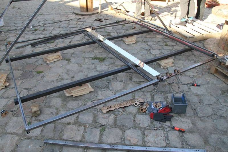
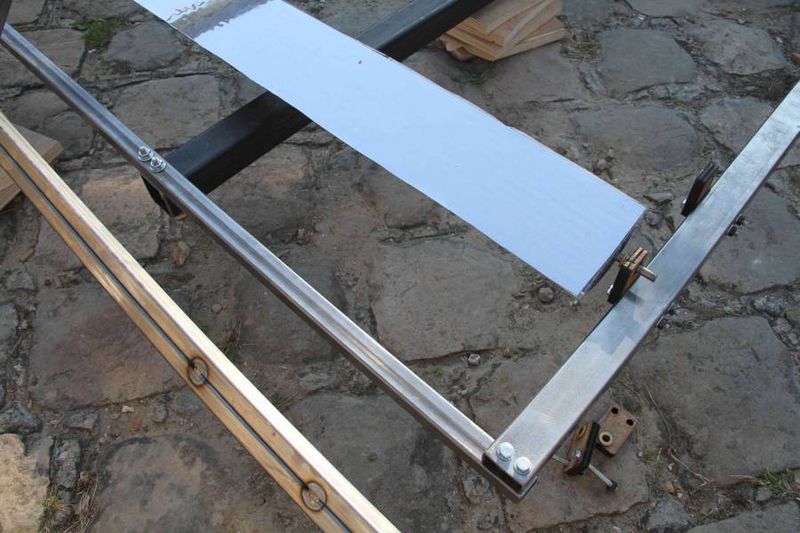
Put all the square tubes on a table: begin with the tubes of 25x25 mm, afterwards put under the tubes of 30x40 mm, assuring that the surface of 40 mm is connected to the extremities of 25x25 mm. Fix them at each angle with a screw of M6 having a length of 60 mm. The tubes can be adjusted if the right angle is verified with a protractor. If the second screw does not enter in the two tubes, the hole alignment should be adjusted by passing the stand alone drill through. Repeat the procedure to all angles in order to complete the fixation.
Étape 5 - Cut the wood support pieces for the motors and the axes of the mirror
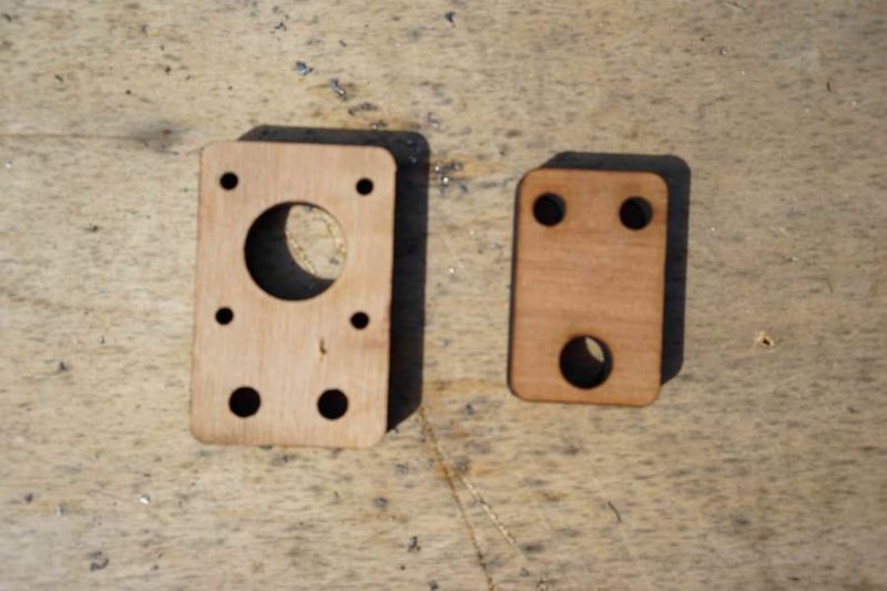
Cut with the laser cutter 20 wood support pieces for the motors and 40 wood support pieces for the axes of the mirror. It is necessary 40 pieces in order to assure one piece to each extremity.
Étape 6 - Fix the wood support pieces on the frame
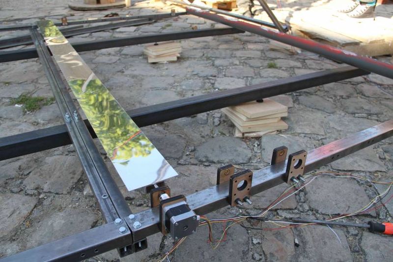
Fix with 2 screws the wood support pieces for the motor on the tube, exterior part and the wood support pieces for the axes of the mirror as indicated on the 3D view. The motor and the axis of the mirror are fixed under the tube, so their wood support pieces should overpass above.
Étape 7 - Assembling the two frames
Two frames are constructed as indicated in the steps 1 to 6.
They are assembled on tubes of 50x50 mm, cut and drilled as indicated in the 3D model.
Notes et références
Project page Next step: SolarOSE_-_Guide_2:_Mirror_facets
Published


 Français
 English
 Deutsch
 Español
 Italiano
 Português