Sommaire
- 1 Introduction
- 2 Étape 1 - Cut the parts
- 3 Étape 2 - Foundations
- 4 Étape 3 - Foundations
- 5 Étape 4 - Deck
- 6 Étape 5 - Section assembly
- 7 Étape 6 - Pledge the layers
- 8 Étape 7 - Skis
- 9 Étape 8 - Stand the sections up vertically
- 10 Étape 9 -
- 11 Étape 10 - Cladding panels
- 12 Étape 11 - Fixing down
- 13 Étape 12 - Insulation
- 14 Étape 13 -
- 15 Étape 14 -
- 16 Étape 15 -
- 17 Étape 16 - Wrap and Openings
- 18 Étape 17 -
- 19 Étape 18 - Windows
- 20 Étape 19 - Flashing tape
- 21 Étape 20 - Steel clip roofing
- 22 Étape 21 -
- 23 Étape 22 -
- 24 Étape 23 -
- 25 Étape 24 -
- 26 Étape 25 -
- 27 Étape 26 -
- 28 Étape 27 -
- 29 Étape 28 -
- 30 Étape 29 - Complete
- 31 Notes et références
- 32 Commentaires
Introduction
Please scan all your site notes from the process and edit this tutorial to share them with us.
By using this tutorial you agree to the following terms and conditions.
Matériaux
Check the list of supplies you will need in the file MicroHouse Pilot Engine.xlsx. We also provide the names of suggested suppliers but you are free to buy them anywhere else.
Buy locally 18mm plywood in the standard sheet size of 2440mm x 1220mm (8' x 4')
All construction is dangerous. Always wear hard hards, eye protection, ear protection (malleting gets very loud), gloves, high visibility outfits and steel-capped boots. Where working at height is required, use a harness. Establish a ‘safety first’ culture on site, and encourage the continuous identification of hazards.
Outils
For this assembly you will need:
- 1 x Step ladder (8ft or 10ft) 5 x Step Ups
- 1 x Mobile scaffolding
- 1 x Roof ladder
- 1 x Large tarpaulin rain cover
- 1 x Marquee (or other enclosed area) to store parts dry and off the ground. 5+ Mallets
- 2+ Electric screwdrivers with as many spare batteries as possible
- 1x Electric drill
- 1x Electric jigsaw
- 1x hand screw driver (to use as a lever)
- 1 x Staple gun
- 2 x Scissors / knife
- 4 x Large clamps
- 1 x Plasterboard filler trowel
Étape 1 - Cut the parts
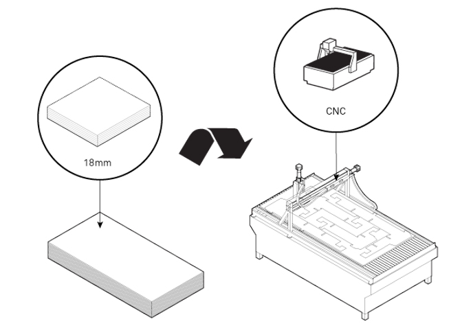
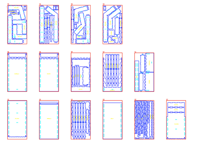
Download on our Github repo the set of milling drawings which can be used by CNC cutter to fabricate the house parts.
Cut the part by a CNC mill using locally bought material. This is 18mm plywood, in the standard sheet size of 2440mm x 1220mm (8' x 4')
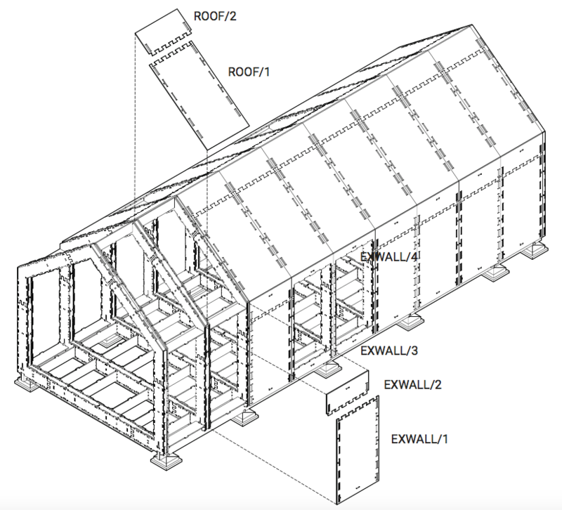
Each component can be combined or adapted to form a structure which responds to an individual site or set of needs.
Étape 2 - Foundations
Site preparation Make sure passers-by can’t wander onto your site. It’s also a good idea to warn neighbours in advance that there’ll be some noise, especially from malleting.
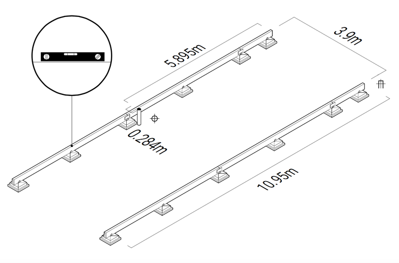
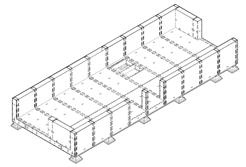
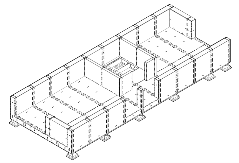
Almost any foundation type can be used, provided it can support the joist ‘rails’. The rails must be level and parallel (+/- 5mm). Consult a builder or engineer to assess design and specification of foundations.
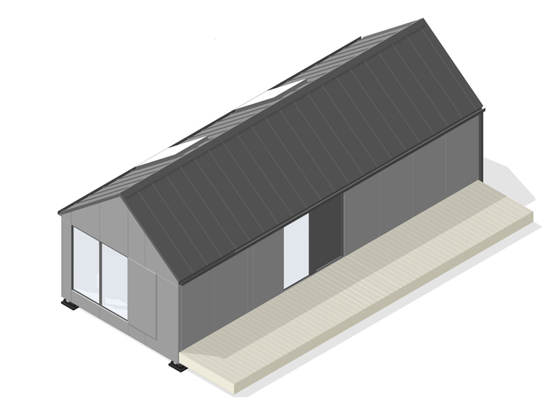
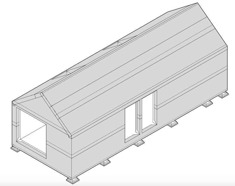
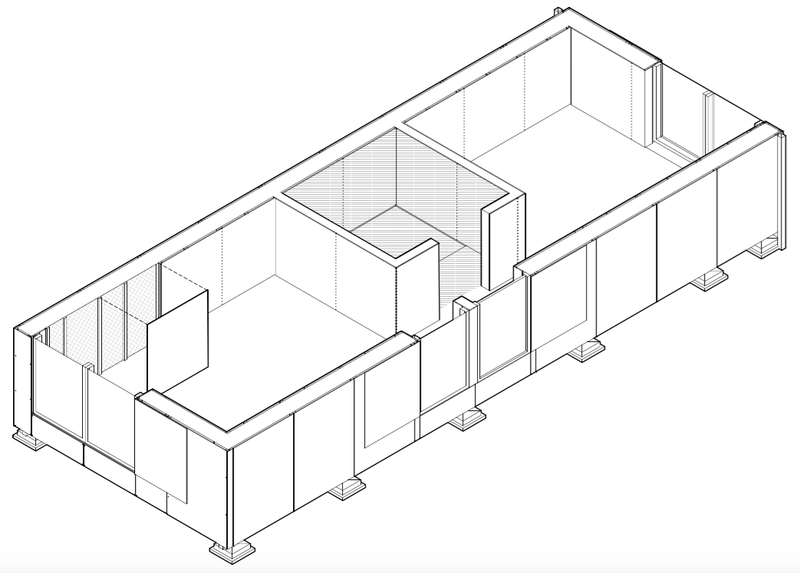
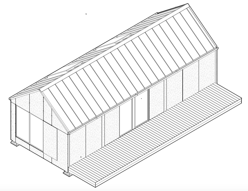
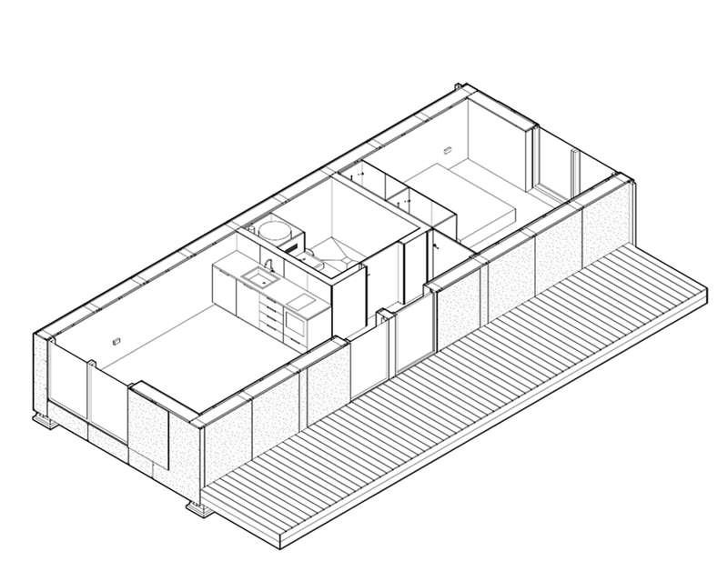
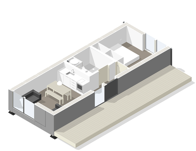
Floor area 37.5m2
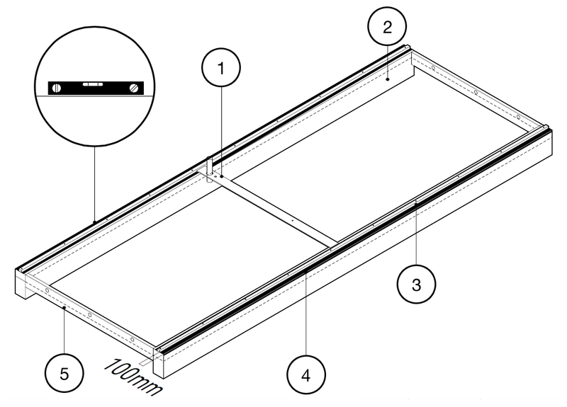
Étape 3 - Foundations
1. Service location jig CNC manufactured to set precise location for service connections.
2. Trench Foundations Depth of concrete will vary.
3. Bolts Fixing into concrete, ready to receive brackets.
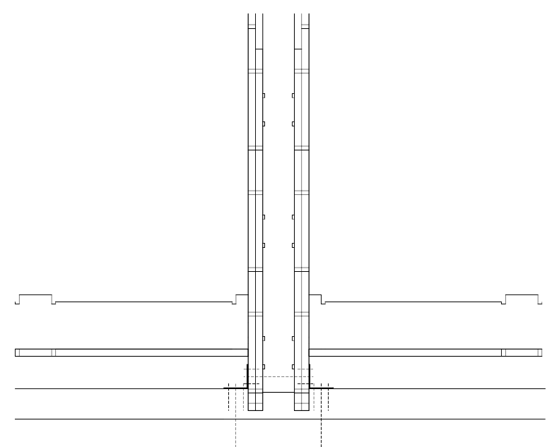
4. DPM Trap two strips of damp proof membrane (DPM) beneath joist rail, with about 200mm sticking out to outer side
5. End walls Concrete or brick wall with ventilation holes.
Étape 4 - Deck
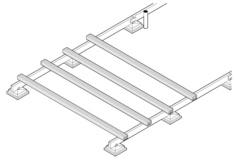
Use timber (for example, the battens) to create a temporary assembly deck. The deck needs to be stable and not bounce when malleted.
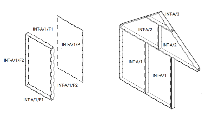
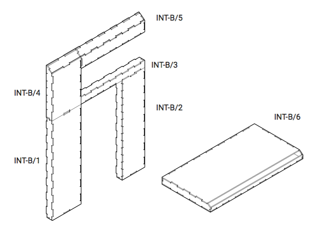
Étape 5 - Section assembly
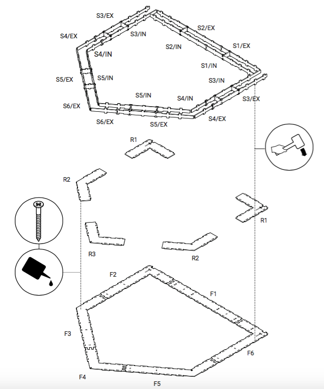
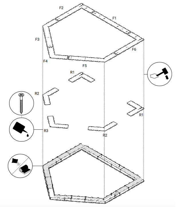
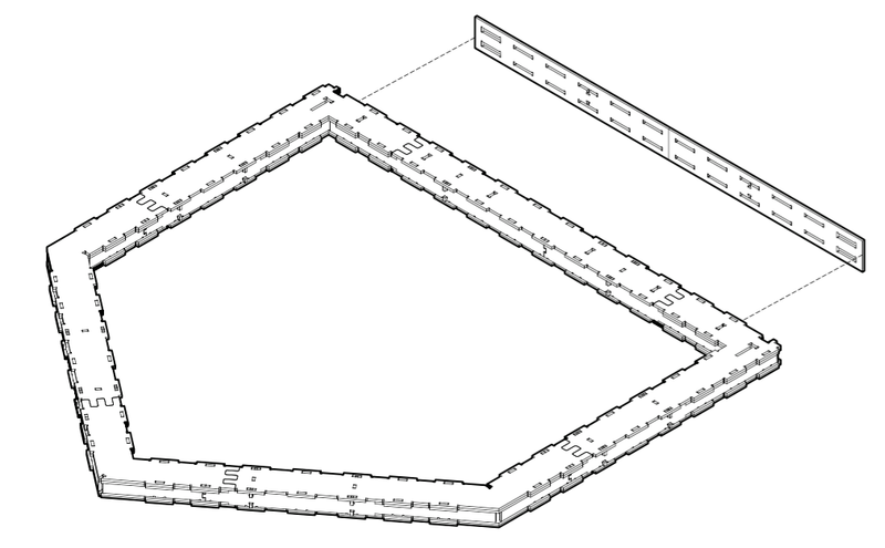
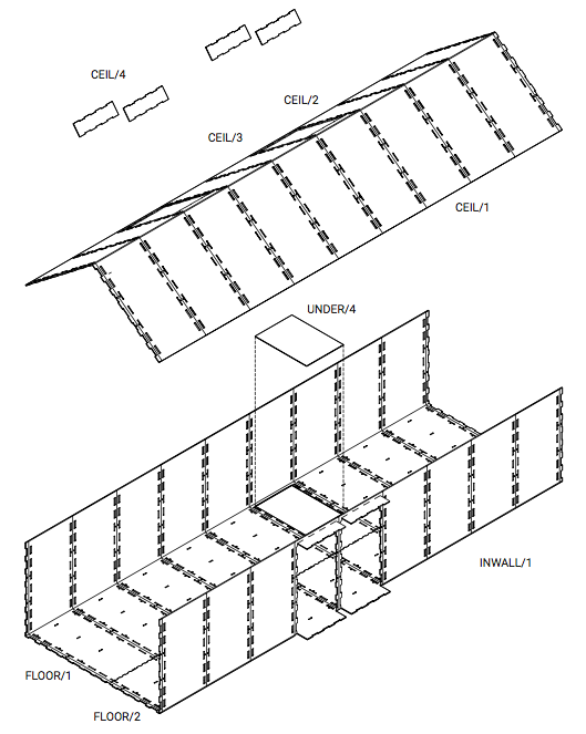
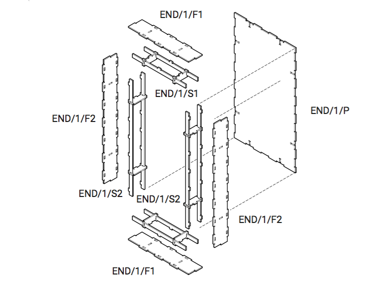
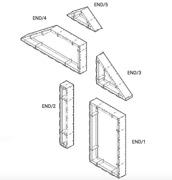
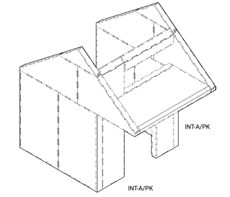
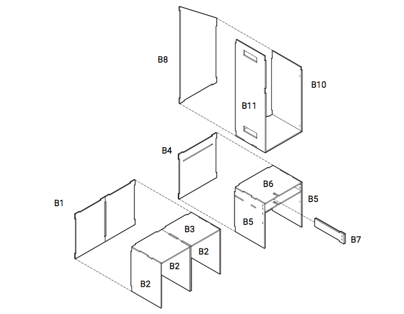
Set out the parts for each section onto the ground, assembly is like a jigsaw.
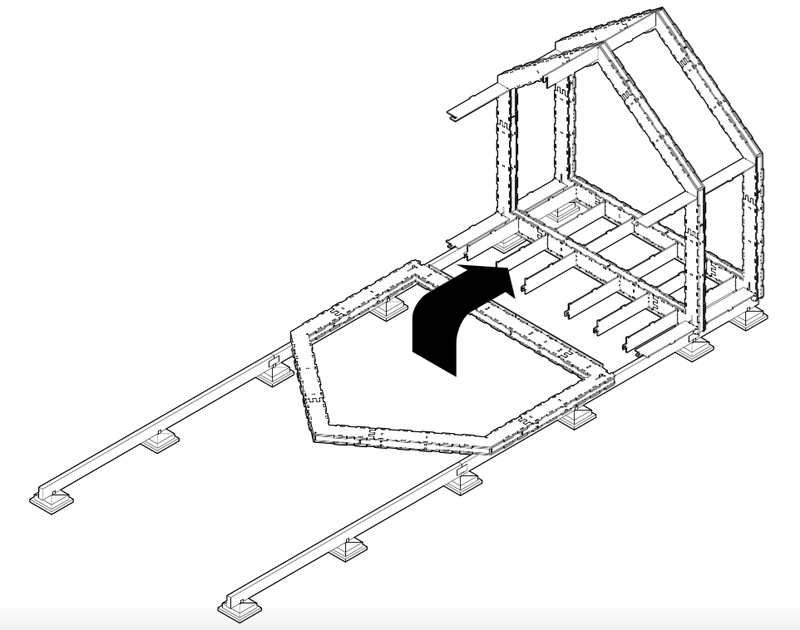
Étape 8 - Stand the sections up vertically
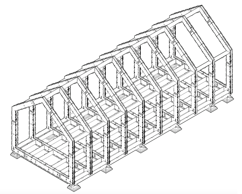
Stand the sections up vertically, positioning them at 600mm intervals.
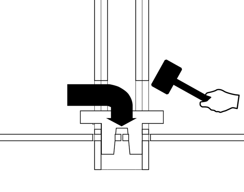
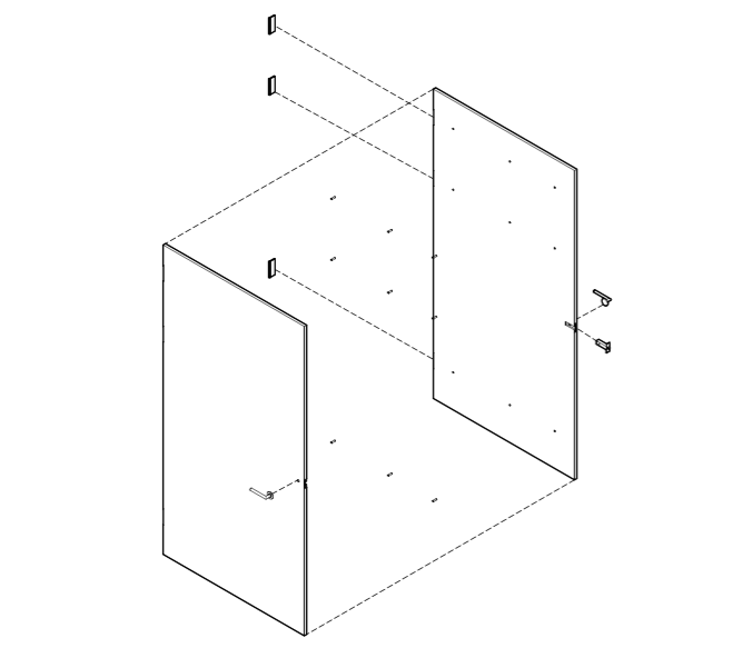
Fit the connector pieces into the slots in the section. These should be staggered alternately. Use the mallet provided on the milling sheets to hammer these tightly into place.
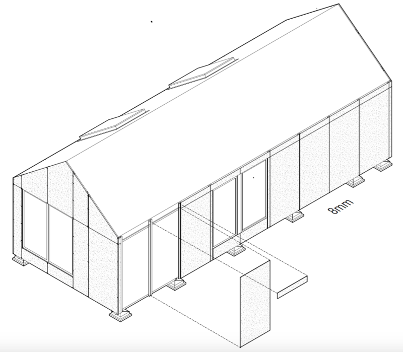
Étape 10 - Cladding panels
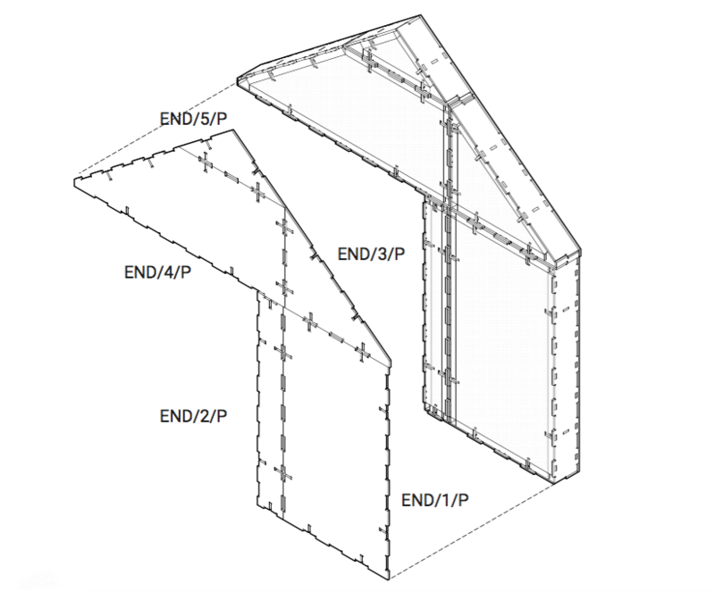
Fit the internal and external cladding panels onto the structure. Internally these usually need to be screwed into place.
Étape 11 - Fixing down
Use bolts and/or large screws, depending on the foundation type. Always consult an engineer or building professional, especially to ensure footings are adequate. During high winds, uplift can be very strong.
Heavy duty brackets Onto rail joist
Étape 12 - Insulation
Drainage
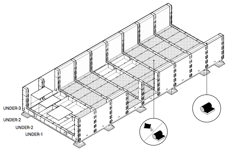
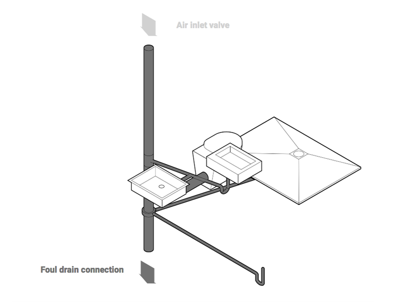
Install underfloor soil pipe plus shower and washing machine drain before surrounding with insulation. You may wish to skip all but the two end bays for now.
Layers
Wherever rolled insulation is used, two layers will be required:
100mm + 150mm = 250mm
Étape 16 - Wrap and Openings
Wrap
Work upwards, giving at least 200mm overlap. Ensure all folds are double wrapped and ‘weathered’ so water will run downwards.
Openings

Don’t cut openings until you are ready to fit windows, unless you need them for access. This way, the chassis is protected from rain during the build.
Étape 17 -
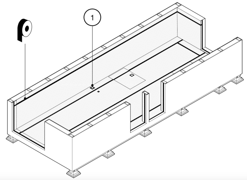
Use airtight tape (Tescon or similar)
1. Seals Around all service penetrations
Vapour barrier
Use a tough vapour barrier (eg Intello) that can be stapled directly. If using a thinner vapour barrier, all staples will need to be over-patched with tape.
Étape 18 - Windows
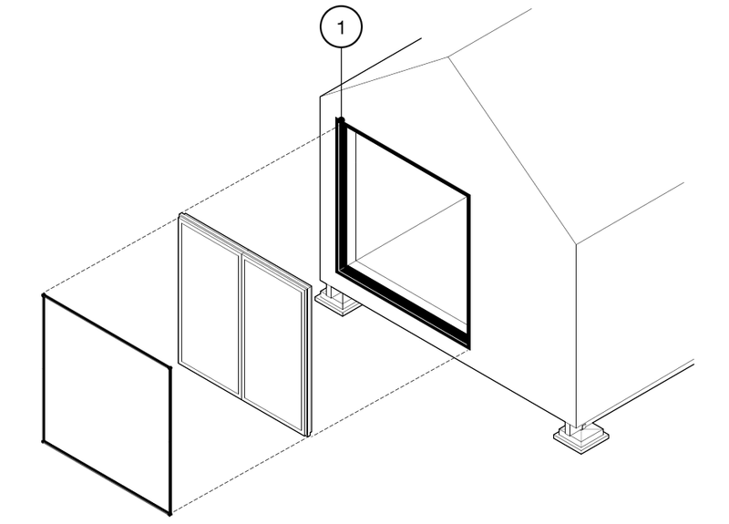
1. Flashing tape
Around entire opening before fitting window
Window unit
Install as per manufacturer’s instructions. In most cases, front face should be flush with chassis.
Expanding tape
Fit to windows seconds before installing unit and allow to expand. Pinch corners slightly to ensure no corner gaps. Check complete seal around unit. If possible add additional flashing tape to exterior. It is impossible to be too thorough. Wind will drive rain into even the smallest crack.
Étape 19 - Flashing tape
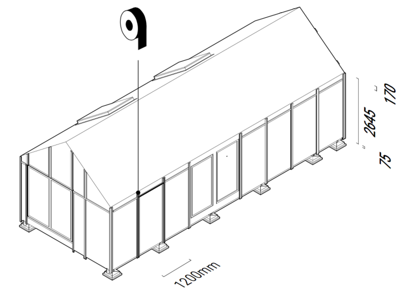
Apply black flashing tape to front of battens. This will be visible in the gaps between panels.
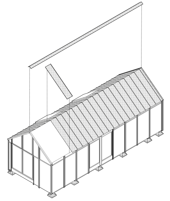
Étape 20 - Steel clip roofing
TATA Colourcoat urban steel roofing. Install as per manufacturer’s instructions.
Étape 25 -
Wet room membrane
Applied over drywall and floorboards in bathroom.
Drywall
Plaster panels fitted using drywall screws, then taped and filled as per manufacturer’s instructions.
Floor overboarding
Screws may be used but not removed to avoid air leaks.
Étape 26 -
No visible screws
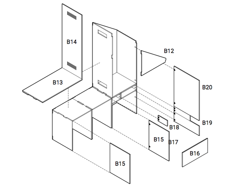
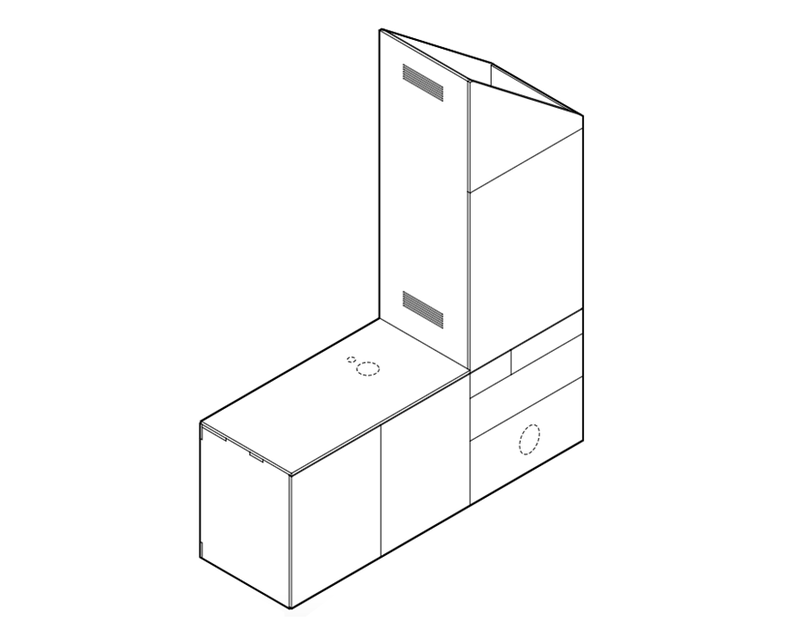
Parts B13, B14, B16 and B21 should be screwed from inside, so no screwheads are visible from outside.
Mirror
Sits behind B13 and B14
Cutting holes
Use a drill or jigsaw to cut holes in the unit to fit around pipes where needed.
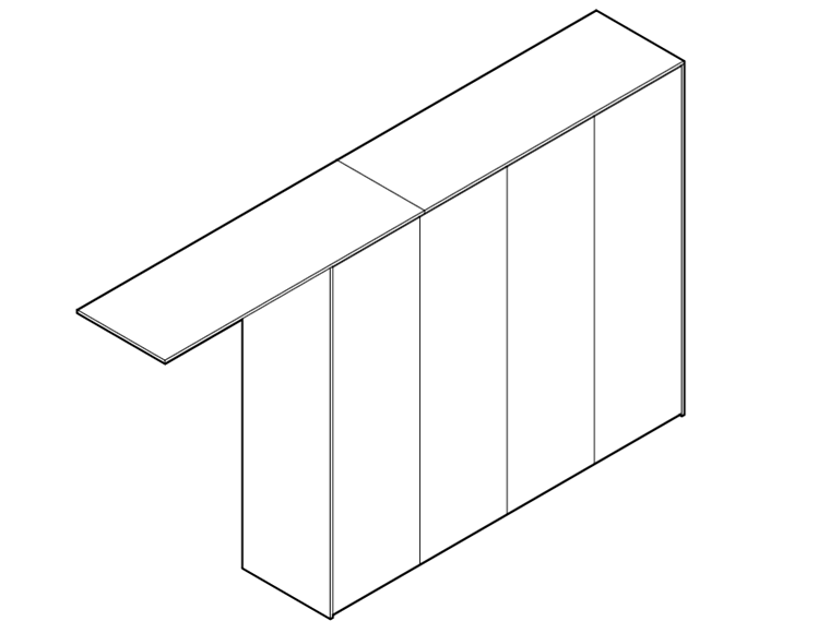
Bumper push latch
Fit by hand to all doors
Notes et références
- If you would like to know more about WikiHouse, visit our website
- If you are interested in a partnership download our full brochure
 Français
 English
 Deutsch
 Español
 Italiano
 Português