(update property name) |
(Mise à jour pour être en accord avec la nouvelle version de la source de la page) |
||
| Ligne 1 : | Ligne 1 : | ||
{{Tuto Details | {{Tuto Details | ||
| − | |Main_Picture= | + | |Main_Picture=Robot__ABC__en_bois_RobotTelecommande_09.jpg_4061.jpeg |
| − | |||
|Description=<div class="mw-translate-fuzzy"> | |Description=<div class="mw-translate-fuzzy"> | ||
Build the "ABC" Robot with a laser cut machine or jigsaw and drill. | Build the "ABC" Robot with a laser cut machine or jigsaw and drill. | ||
| Ligne 18 : | Ligne 17 : | ||
}} | }} | ||
{{Introduction | {{Introduction | ||
| − | |Introduction=< | + | |Introduction=<div class="mw-translate-fuzzy"> |
| + | You will learn to build a small robot controlled by remote control. This robot is made of wood with an electronic board (arduino uno) and a control extension for both motors. | ||
| + | </div> | ||
}} | }} | ||
{{TutoVideo | {{TutoVideo | ||
| Ligne 25 : | Ligne 26 : | ||
}} | }} | ||
{{Materials | {{Materials | ||
| + | |Prerequisites={{Prerequisites}} | ||
| + | |Tuto_Attachments={{Tuto Attachments | ||
| + | |Attachment=Robot-1.ino.pdf | ||
| + | }} | ||
| + | |ExternalAttachmentsLinks={{ExternalAttachmentsLinks | ||
| + | |ExternalAttachmentsLinks=https://framadrive.org/remote.php/webdav/Robot%20%22ABC%22%20V1%20Fran%C3%A7ais%20-%20English%20-%20Deutsch%20-%20Espa%C3%B1ol%20-%20Italiano/Code%20arduino%20-%20Arduino%20code%20-%20Arduino-Zahl%20-%20C%C3%B3digo%20Arduino%20-%20Codice%20Arduino/robot.ino | ||
| + | }} | ||
|Material=1x wooden board thickness 5mm (13/64 inch) - 610mm (2 ft 1/64 inch) - 407mm (1 ft 4 1/32 inch) | |Material=1x wooden board thickness 5mm (13/64 inch) - 610mm (2 ft 1/64 inch) - 407mm (1 ft 4 1/32 inch) | ||
| Ligne 69 : | Ligne 77 : | ||
*Clamping pliers (maintain spacers and nuts) | *Clamping pliers (maintain spacers and nuts) | ||
</div> | </div> | ||
| − | |||
| − | |||
| − | |||
| − | |||
| − | |||
| − | |||
| − | |||
}} | }} | ||
| − | |||
{{Tuto Step | {{Tuto Step | ||
|Step_Title=blueprint | |Step_Title=blueprint | ||
| Ligne 90 : | Ligne 90 : | ||
A quoi correspond le 1er chiffre avec X ? | A quoi correspond le 1er chiffre avec X ? | ||
| − | le 1er chiffre correspond au nombre de fois ou la pièce est utilisé, par exemple 1x001 veut dire que la pièce 001 et utilisé une seule fois) - 001 correspond au nom du fichier utilisé soit le fichier 001.SLDPRT (solidworks) | + | le 1er chiffre correspond au nombre de fois ou la pièce est utilisé, par exemple 1x001 veut dire que la pièce 001 et utilisé une seule fois) - 001 correspond au nom du fichier utilisé soit le fichier 001.SLDPRT (solidworks) |
| − | Vous pouvez télécharger et ouvrir le fichier suivant : https://framadrive.org/s/7SHD4NXCia3dvFL (ce fichier nécessite l'installation du logiciel INKSCAPE téléchargeable avec ce lien : https://inkscape.org/fr/). | + | Vous pouvez télécharger et ouvrir le fichier suivant : https://framadrive.org/s/7SHD4NXCia3dvFL (ce fichier nécessite l'installation du logiciel INKSCAPE téléchargeable avec ce lien : https://inkscape.org/fr/). |
Dans ce fichier intitulé "Robot_ABC_V1.svg" figure les pièces à découper. | Dans ce fichier intitulé "Robot_ABC_V1.svg" figure les pièces à découper. | ||
| Ligne 120 : | Ligne 120 : | ||
}} | }} | ||
{{Tuto Step | {{Tuto Step | ||
| − | |Step_Title=< | + | |Step_Title=<div class="mw-translate-fuzzy"> |
| + | Base | ||
| + | </div> | ||
|Step_Content=<div class="mw-translate-fuzzy"> | |Step_Content=<div class="mw-translate-fuzzy"> | ||
Let's start with the base by adding support with it's stack connected to the 3 green LEDs. | Let's start with the base by adding support with it's stack connected to the 3 green LEDs. | ||
| Ligne 133 : | Ligne 135 : | ||
}} | }} | ||
{{Tuto Step | {{Tuto Step | ||
| − | |Step_Title=< | + | |Step_Title=<div class="mw-translate-fuzzy"> |
| − | |Step_Content=< | + | Bottom |
| + | </div> | ||
| + | |Step_Content=<div class="mw-translate-fuzzy"> | ||
| + | Insert 4 M4 screws 50 mm with their nuts and spacers, then turn the assembly to secure the swivel caster wheel. | ||
| + | </div> | ||
|Step_Picture_00=RobotTelecommande 05a.jpg | |Step_Picture_00=RobotTelecommande 05a.jpg | ||
|Step_Picture_01=RobotTelecommande 05b.jpg | |Step_Picture_01=RobotTelecommande 05b.jpg | ||
}} | }} | ||
{{Tuto Step | {{Tuto Step | ||
| − | |Step_Title=< | + | |Step_Title=<div class="mw-translate-fuzzy"> |
| − | |Step_Content=< | + | Assembly Base + Bottom |
| + | </div> | ||
| + | |Step_Content=<div class="mw-translate-fuzzy"> | ||
| + | Assemble the base and the underside by screwing each screw. | ||
| + | </div> | ||
|Step_Picture_00=RobotTelecommande 06a.jpg | |Step_Picture_00=RobotTelecommande 06a.jpg | ||
}} | }} | ||
{{Tuto Step | {{Tuto Step | ||
| − | |Step_Title=< | + | |Step_Title=<div class="mw-translate-fuzzy"> |
| − | |Step_Content=< | + | Electronic |
| + | </div> | ||
| + | |Step_Content=<div class="mw-translate-fuzzy"> | ||
| + | Attach the motor to the wooden sides. | ||
| + | </div> | ||
|Step_Picture_00=RobotTelecommande 07a.jpg | |Step_Picture_00=RobotTelecommande 07a.jpg | ||
}} | }} | ||
{{Tuto Step | {{Tuto Step | ||
|Step_Title=Final assembly | |Step_Title=Final assembly | ||
| − | |Step_Content=< | + | |Step_Content=<div class="mw-translate-fuzzy"> |
| + | Assemble the roundings and the sides with motor in the illustration seen in step 4. | ||
| + | </div> | ||
|Step_Picture_00=RobotTelecommande 08.jpg | |Step_Picture_00=RobotTelecommande 08.jpg | ||
}} | }} | ||
{{Tuto Step | {{Tuto Step | ||
| − | |Step_Title=< | + | |Step_Title=<div class="mw-translate-fuzzy"> |
| + | Overview of the robot | ||
| + | </div> | ||
|Step_Content=Prochaine évolution mettre un capteur ultrason pour détection et évitement d’obstacle et un suiveur de ligne. | |Step_Content=Prochaine évolution mettre un capteur ultrason pour détection et évitement d’obstacle et un suiveur de ligne. | ||
|Step_Picture_00=RobotTelecommande 09.jpg | |Step_Picture_00=RobotTelecommande 09.jpg | ||
| Ligne 163 : | Ligne 181 : | ||
{{Notes | {{Notes | ||
|Notes= | |Notes= | ||
| + | }} | ||
| + | {{PageLang | ||
}} | }} | ||
{{Tuto Status | {{Tuto Status | ||
|Complete=Published | |Complete=Published | ||
}} | }} | ||
| + | {{Separator}} | ||
Version du 21 février 2023 à 21:35
Build the "ABC" Robot with a laser cut machine or jigsaw and drill.
Introduction
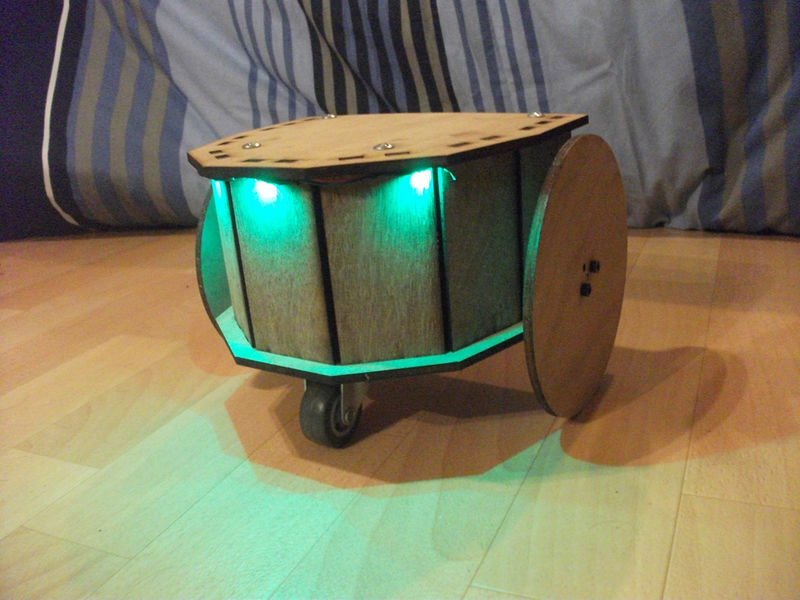
You will learn to build a small robot controlled by remote control. This robot is made of wood with an electronic board (arduino uno) and a control extension for both motors.
Youtube
Matériaux
1x wooden board thickness 5mm (13/64 inch) - 610mm (2 ft 1/64 inch) - 407mm (1 ft 4 1/32 inch)
1x Arduino Uno
http://www.robotshop.com/en/arduino-uno-r3-usb-microcontroller.html
Product Code : RB-Ard-34
1x Green LED Strip Flexible https://www.banggood.com/50CM-Waterproof-USB-SMD3528-TV-Background-Computer-LED-Strip-Tape-Flexible-Light-DC5V-p-1102998.html?rmmds=search
1x power supply battery (for LED strip) http://www.robotshop.com/en/waterproof-3xaa-battery-case-switch.html
2x Motors DC http://www.robotshop.com/en/makeblock-25mm-dc-motor-kit-blue.html
1x Motor Shield http://www.robotshop.com/en/arduino-motor-shield-rev3.html
1x infrared sensor 1x Infrared Remote Control http://www.robotshop.com/en/dfrobot-ir-remote-kit-arduino.html
2x battery holders (6 x 1,5 Volt LR6 batteries) (Arduino Uno main power supply)
4x Batteries 4,5Volts (2 pack mounted in parallel, each pack includes 2 4.5V batteries mounted in series) - (it makes a power supply under 9V for the power supply I paralleled to have a longer battery life )
8x M4 Nuts http://www.screwfix.com/p/easyfix-hex-nuts-a2-stainless-steel-m4-100-pack/8398t
8x Screw M4 - 50 http://uk.farnell.com/tr-fastenings/m450-psstmcz100/screw-slt-pan-steel-bzp-m4x50/dp/1419307
4x M4 Spacer http://uk.farnell.com/c/fasteners-mechanical/fasteners-fixings/spacers-feet/standoffs?thread-size-metric=m4
1x swivel caster wheel http://www.robotshop.com/en/2-swivel-caster-wheel.html
Outils
- Cruciform screwdriver
- Alen wrench 1.5 mm (screw tightening M3)
- Clamping pliers (maintain spacers and nuts)
Étape 1 - blueprint
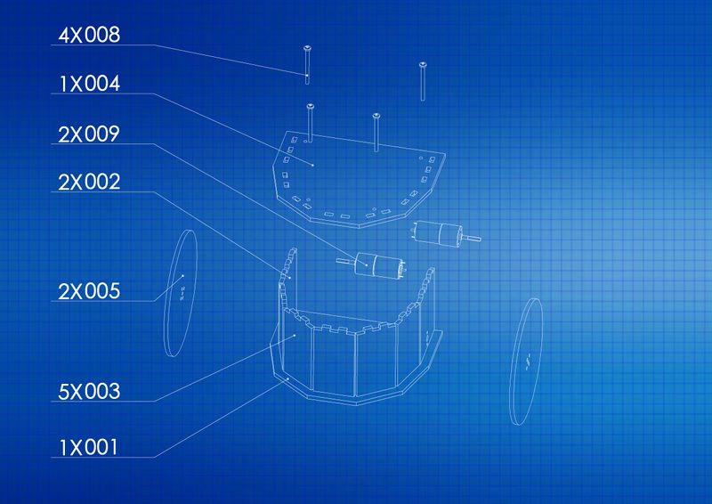
Here are the plans of each piece to make the robot with dimension (in mm)
Downloading files: https://framadrive.org/index.php/s/oHlHOqSsc18I4U1
explication du dessin :
A quoi correspond le 1er chiffre avec X ?
le 1er chiffre correspond au nombre de fois ou la pièce est utilisé, par exemple 1x001 veut dire que la pièce 001 et utilisé une seule fois) - 001 correspond au nom du fichier utilisé soit le fichier 001.SLDPRT (solidworks)
Vous pouvez télécharger et ouvrir le fichier suivant : https://framadrive.org/s/7SHD4NXCia3dvFL (ce fichier nécessite l'installation du logiciel INKSCAPE téléchargeable avec ce lien : https://inkscape.org/fr/).
Dans ce fichier intitulé "Robot_ABC_V1.svg" figure les pièces à découper.
A quoi correspond le 3 chiffres?
Au nom des pièces
001.SLDPRT = la base
002.SLDPRT = les supports moteurs
003.SLDPRT = les arcs
004.SLDPRT = le dessus
005.SLDPRT = les roues
008.SLDPRT = Les vis M4 50mm
To use a laser cutter see the list of FabLab to find the nearest to you: http://www.makery.info/map-labs/
Pour se servir d'une découpeuse laser voir la liste des FabLab pour trouver le plus proche de chez vous : http://www.makery.info/map-labs/
Étape 2 -
Base
Base
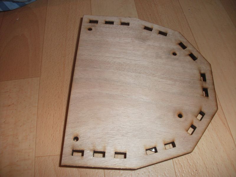
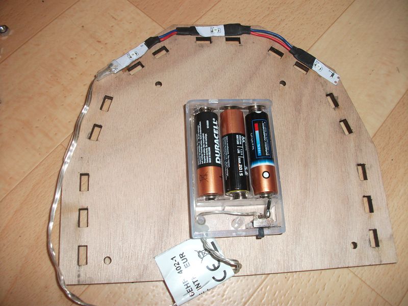
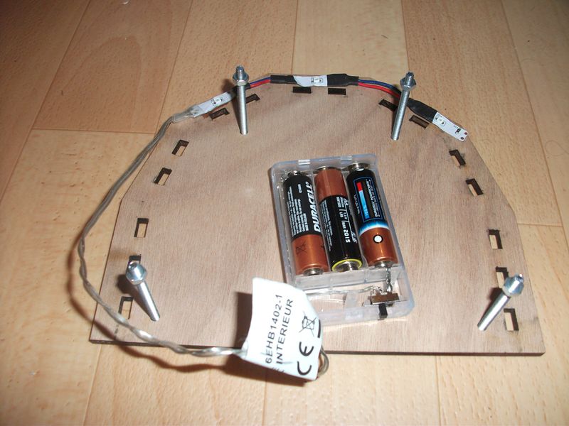
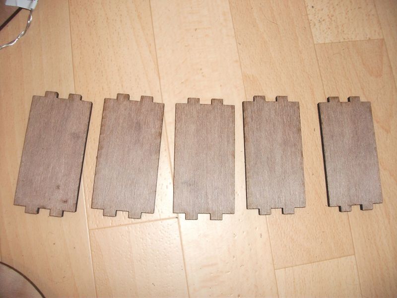
Let's start with the base by adding support with it's stack connected to the 3 green LEDs.
Take 4 screws M4 insert them in the 4 holes then fix 1 nut on each screws.
Étape 3 -
Bottom
Bottom
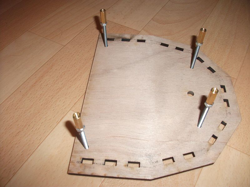
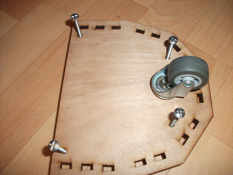
Insert 4 M4 screws 50 mm with their nuts and spacers, then turn the assembly to secure the swivel caster wheel.
Étape 6 - Final assembly
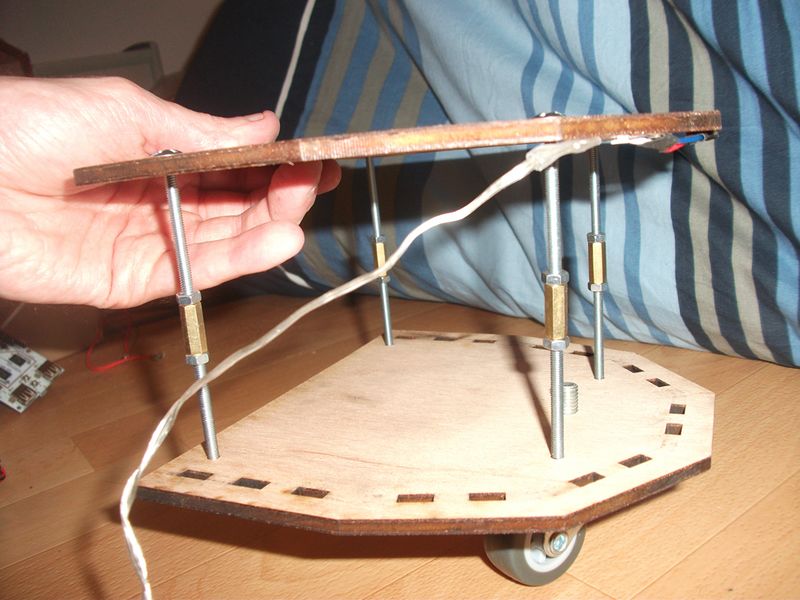
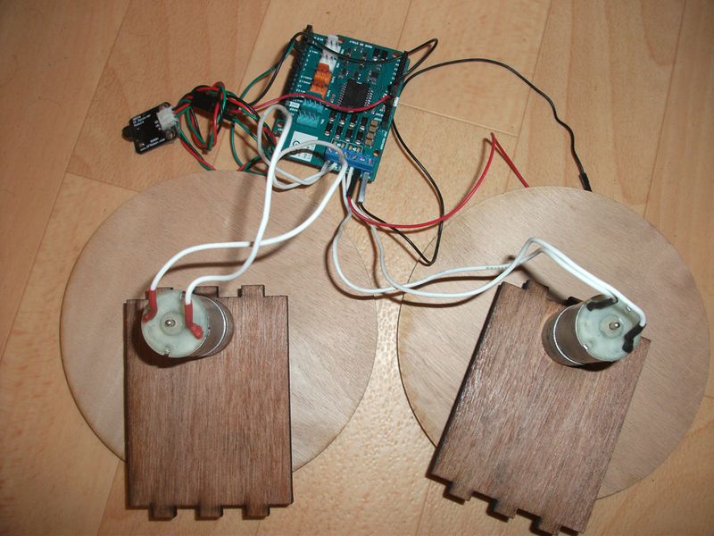
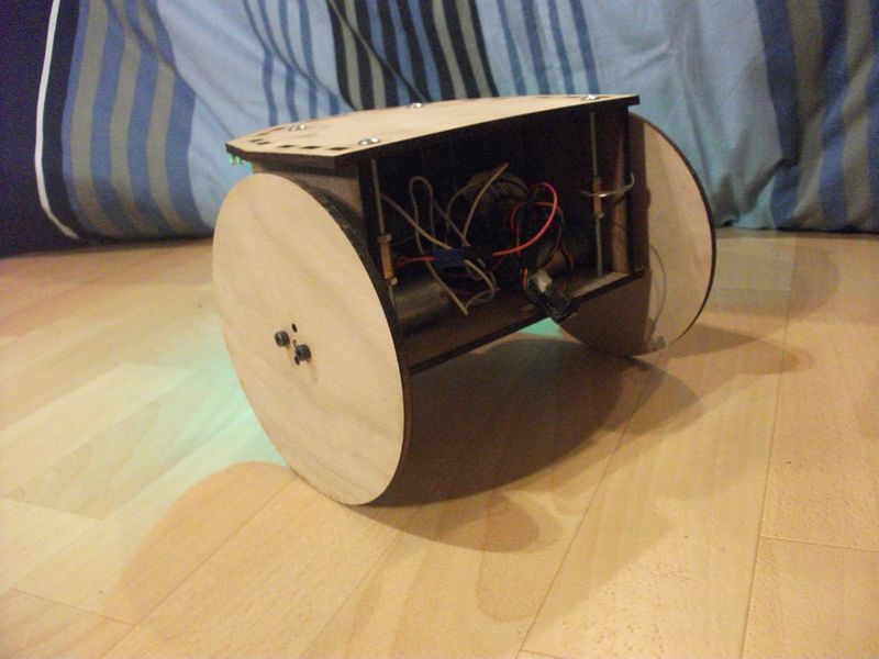
Assemble the roundings and the sides with motor in the illustration seen in step 4.
Étape 7 -
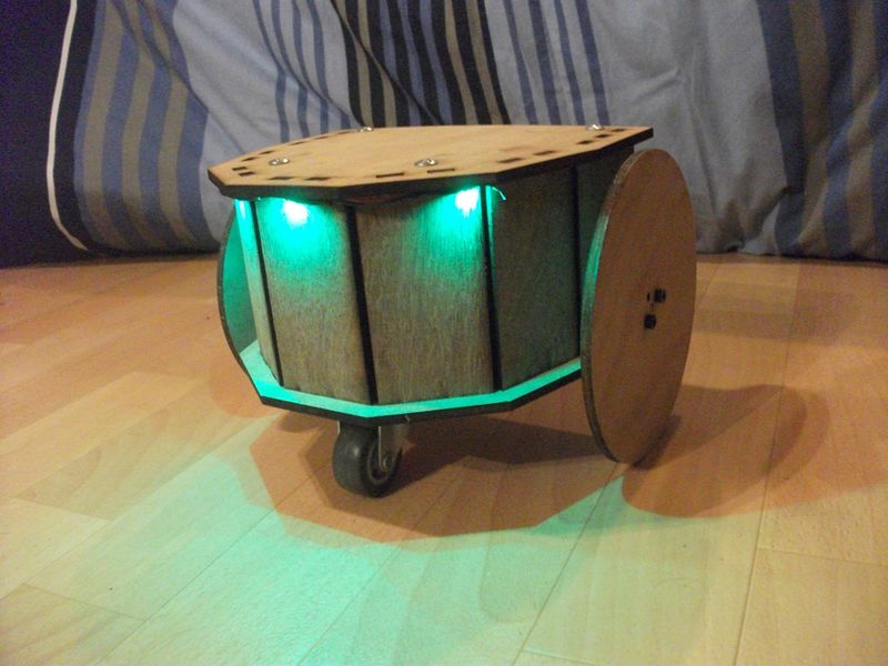
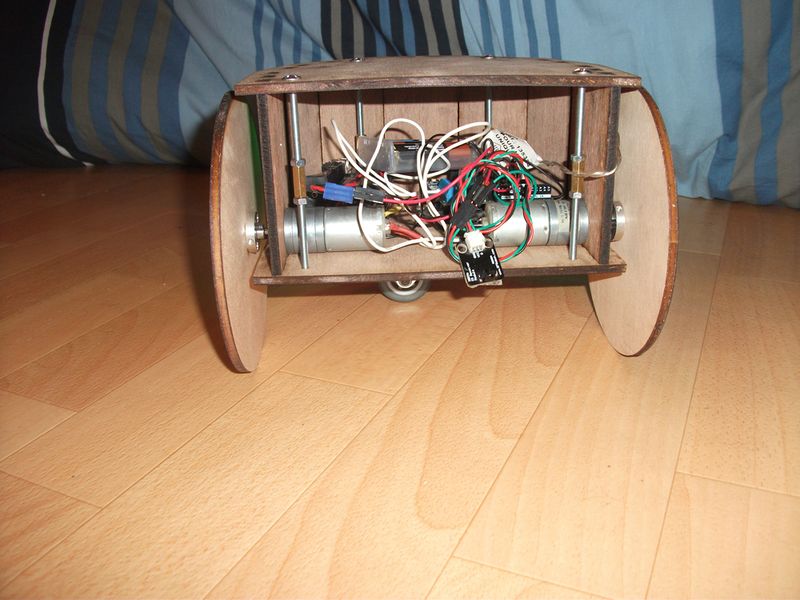
Overview of the robot
Overview of the robot
Prochaine évolution mettre un capteur ultrason pour détection et évitement d’obstacle et un suiveur de ligne.
Published
 Français
 English
 Deutsch
 Español
 Italiano
 Português