(Mise à jour pour être en accord avec la nouvelle version de la source de la page) |
(update property name) |
||
| (Une révision intermédiaire par un autre utilisateur non affichée) | |||
| Ligne 1 : | Ligne 1 : | ||
| − | {{ | + | {{Tuto Details |
| − | |||
| − | |||
| − | |||
|Main_Picture=Electronic_textile_bag_1.PNG | |Main_Picture=Electronic_textile_bag_1.PNG | ||
|Licences=Attribution (CC BY) | |Licences=Attribution (CC BY) | ||
| Ligne 14 : | Ligne 11 : | ||
|Currency=EUR (€) | |Currency=EUR (€) | ||
|Tags=tote bag, Arduino, e-textile, electronic | |Tags=tote bag, Arduino, e-textile, electronic | ||
| + | |SourceLanguage=none | ||
| + | |Language=en | ||
| + | |IsTranslation=1 | ||
}} | }} | ||
| − | {{ | + | {{Introduction |
|Introduction=In this tutorial, you will learn how to create an electronic textile bag, to be used in the context of educational activities on electronics and coding. | |Introduction=In this tutorial, you will learn how to create an electronic textile bag, to be used in the context of educational activities on electronics and coding. | ||
| + | |||
| + | A French version of this tutorial is available [https://drive.google.com/file/d/1UKejIQmnuxjVb0394a-BYKdsV85QhQDO/view?usp=sharing online] / Une version en français de ce tutoriel est également disponible [https://drive.google.com/file/d/1UKejIQmnuxjVb0394a-BYKdsV85QhQDO/view?usp=sharing en ligne]. | ||
}} | }} | ||
| − | {{ | + | {{Materials |
|Material=* conductive thread (about 13 meters) | |Material=* conductive thread (about 13 meters) | ||
* 2mm thick textile (or thinner) | * 2mm thick textile (or thinner) | ||
| Ligne 36 : | Ligne 38 : | ||
* needles and thread | * needles and thread | ||
}} | }} | ||
| − | {{ | + | {{Separator}} |
| − | {{ | + | {{Tuto Step |
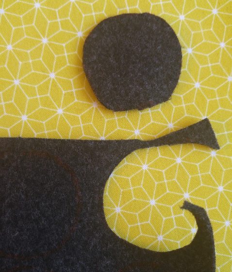
|Step_Title=Cut 4 round textile patches | |Step_Title=Cut 4 round textile patches | ||
|Step_Content=One of the patches must be slightly bigger than the other 3. | |Step_Content=One of the patches must be slightly bigger than the other 3. | ||
|Step_Picture_00=Electronic_textile_bag_2.PNG | |Step_Picture_00=Electronic_textile_bag_2.PNG | ||
}} | }} | ||
| − | {{ | + | {{Tuto Step |
|Step_Title=Prepare the Led patch | |Step_Title=Prepare the Led patch | ||
|Step_Content=Shorten the longer leg of the Led and solder a 250 ohm resistor to its end. | |Step_Content=Shorten the longer leg of the Led and solder a 250 ohm resistor to its end. | ||
| Ligne 56 : | Ligne 58 : | ||
|Step_Picture_03=Electronic_textile_bag_6.PNG | |Step_Picture_03=Electronic_textile_bag_6.PNG | ||
}} | }} | ||
| − | {{ | + | {{Tuto Step |
|Step_Title=Prepare the speaker and the mini vibrating motor patches | |Step_Title=Prepare the speaker and the mini vibrating motor patches | ||
|Step_Content=Apply the same procedure as the one described above, to create the patches for the 8ohm speaker as well as the one for the mini vibrating motor. | |Step_Content=Apply the same procedure as the one described above, to create the patches for the 8ohm speaker as well as the one for the mini vibrating motor. | ||
| Ligne 65 : | Ligne 67 : | ||
|Step_Picture_00=Electronic_textile_bag_7.PNG | |Step_Picture_00=Electronic_textile_bag_7.PNG | ||
}} | }} | ||
| − | {{ | + | {{Tuto Step |
|Step_Title=Prepare the photoresistor patch | |Step_Title=Prepare the photoresistor patch | ||
|Step_Content=Use the biggest textile patch for the photoresistor. | |Step_Content=Use the biggest textile patch for the photoresistor. | ||
| Ligne 74 : | Ligne 76 : | ||
|Step_Picture_00=Electronic_textile_bag_8.PNG | |Step_Picture_00=Electronic_textile_bag_8.PNG | ||
}} | }} | ||
| − | {{ | + | {{Tuto Step |
|Step_Title=Choose the design of your e-textile bag | |Step_Title=Choose the design of your e-textile bag | ||
|Step_Content=Position all 4 patches on the front of the textile bag, and draw lines with a pencil, to determine where you will be sewing the conductive thread, and where you will position the arduino board. This will also give you a rough idea of how much conductive thread you will need to use to connect all patches to the board. | |Step_Content=Position all 4 patches on the front of the textile bag, and draw lines with a pencil, to determine where you will be sewing the conductive thread, and where you will position the arduino board. This will also give you a rough idea of how much conductive thread you will need to use to connect all patches to the board. | ||
| Ligne 82 : | Ligne 84 : | ||
|Step_Picture_01=Electronic_textile_bag_10.PNG | |Step_Picture_01=Electronic_textile_bag_10.PNG | ||
}} | }} | ||
| − | {{ | + | {{Tuto Step |
|Step_Title=Sew the top of the snap buttons on to the textile bag | |Step_Title=Sew the top of the snap buttons on to the textile bag | ||
|Step_Content=Draw with a pencil the position where the snap buttons will need to be attached to the textile bag, then sew them to the bag. | |Step_Content=Draw with a pencil the position where the snap buttons will need to be attached to the textile bag, then sew them to the bag. | ||
| Ligne 90 : | Ligne 92 : | ||
|Step_Picture_01=Electronic_textile_bag_12.PNG | |Step_Picture_01=Electronic_textile_bag_12.PNG | ||
}} | }} | ||
| − | {{ | + | {{Tuto Step |
|Step_Title=Sew the conductive thread to the textile bag | |Step_Title=Sew the conductive thread to the textile bag | ||
|Step_Content=Once all snap buttons are in place you need to make all necessary connections using the conductive thread | |Step_Content=Once all snap buttons are in place you need to make all necessary connections using the conductive thread | ||
| Ligne 102 : | Ligne 104 : | ||
|Step_Picture_03=Electronic_textile_bag_16.PNG | |Step_Picture_03=Electronic_textile_bag_16.PNG | ||
}} | }} | ||
| − | {{ | + | {{Tuto Step |
|Step_Title=Solder jumper wires to the safety pins | |Step_Title=Solder jumper wires to the safety pins | ||
|Step_Content= | |Step_Content= | ||
| Ligne 108 : | Ligne 110 : | ||
|Step_Picture_01=Electronic_textile_bag_18.PNG | |Step_Picture_01=Electronic_textile_bag_18.PNG | ||
}} | }} | ||
| − | {{ | + | {{Tuto Step |
|Step_Title=Sew the Arduino board to the inside of the textile bag | |Step_Title=Sew the Arduino board to the inside of the textile bag | ||
|Step_Content= | |Step_Content= | ||
|Step_Picture_00=Electronic_textile_bag_19.PNG | |Step_Picture_00=Electronic_textile_bag_19.PNG | ||
}} | }} | ||
| − | {{ | + | {{Tuto Step |
|Step_Title=Cover all safety pins with some tape to avoid short circuits and unwanted connections | |Step_Title=Cover all safety pins with some tape to avoid short circuits and unwanted connections | ||
|Step_Content= | |Step_Content= | ||
|Step_Picture_00=Electronic_textile_bag_20.PNG | |Step_Picture_00=Electronic_textile_bag_20.PNG | ||
}} | }} | ||
| − | {{ | + | {{Notes |
|Notes=This tutorial has been developed as part of the [http://www.digijeunes.com/projets/itech/ I TECH] project, co-financed by the Erasmus + program of the European Commission. | |Notes=This tutorial has been developed as part of the [http://www.digijeunes.com/projets/itech/ I TECH] project, co-financed by the Erasmus + program of the European Commission. | ||
For more info contact us on info@digijeunes.com. | For more info contact us on info@digijeunes.com. | ||
}} | }} | ||
| − | {{ | + | {{Tuto Status |
|Complete=Published | |Complete=Published | ||
}} | }} | ||
Version actuelle datée du 9 décembre 2019 à 11:32
Sommaire
- 1 Introduction
- 2 Étape 1 - Cut 4 round textile patches
- 3 Étape 2 - Prepare the Led patch
- 4 Étape 3 - Prepare the speaker and the mini vibrating motor patches
- 5 Étape 4 - Prepare the photoresistor patch
- 6 Étape 5 - Choose the design of your e-textile bag
- 7 Étape 6 - Sew the top of the snap buttons on to the textile bag
- 8 Étape 7 - Sew the conductive thread to the textile bag
- 9 Étape 8 - Solder jumper wires to the safety pins
- 10 Étape 9 - Sew the Arduino board to the inside of the textile bag
- 11 Étape 10 - Cover all safety pins with some tape to avoid short circuits and unwanted connections
- 12 Notes et références
- 13 Commentaires
Introduction
In this tutorial, you will learn how to create an electronic textile bag, to be used in the context of educational activities on electronics and coding.
A French version of this tutorial is available online / Une version en français de ce tutoriel est également disponible en ligne.
Matériaux
- conductive thread (about 13 meters)
- 2mm thick textile (or thinner)
- 1 x Led
- 1 x 8 ohm speaker
- 1 x mini vibrating motor
- 1 x photoresistor
- 1 x textile bag
- 1 x Arduino board + power cable
- 6 x jumper wires
- 6 x small safety pins (around 4 cm long)
- 9 x metal snap buttons (make sure they are not coated and are conductive)
- 1 x 250 ohm resistor (or similar)
- electric wire (about 1 meter)
Outils
- 1 x soldering iron
- Pc with Arduino IDE installed
- needles and thread
Étape 2 - Prepare the Led patch
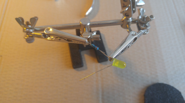
Shorten the longer leg of the Led and solder a 250 ohm resistor to its end.
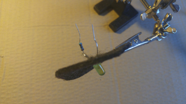
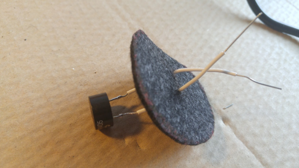
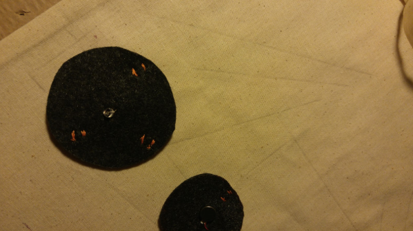
Insert both legs of the Led into the textile patch. Do not leave any space between the textile patch and the base of the Led.
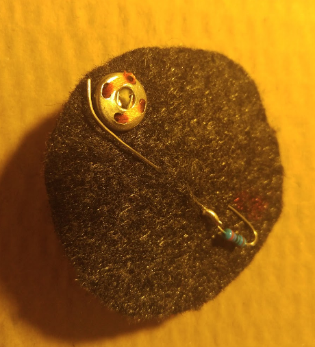
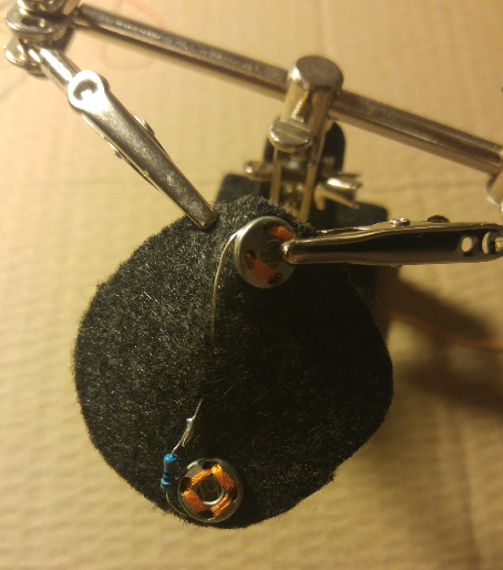
Sew the bottom part of two snap buttons to the textile patch. These will serve to connect the legs of the Led.
Solder both legs of the Led to the snap buttons.
Étape 3 - Prepare the speaker and the mini vibrating motor patches
Apply the same procedure as the one described above, to create the patches for the 8ohm speaker as well as the one for the mini vibrating motor.
You may need to use some electric wire to extend the terminals of the electronic components and be able to solder them to the snap buttons
Neither the mini vibrating motor nor the speaker need a resistor.
Étape 4 - Prepare the photoresistor patch
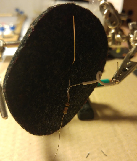
Use the biggest textile patch for the photoresistor.
First insert both legs of the photoresistor into the textile patch.
Then start the soldering. Solder a 1kohm resistor as well as a piece of electric wire to the negative leg of the photoresistor (the shorter of the two legs).
Étape 5 - Choose the design of your e-textile bag
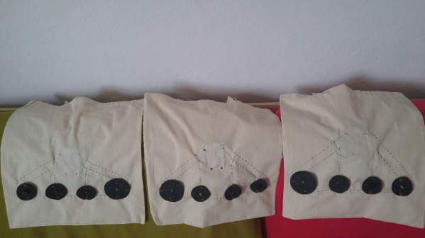
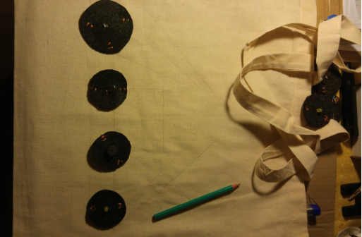
Position all 4 patches on the front of the textile bag, and draw lines with a pencil, to determine where you will be sewing the conductive thread, and where you will position the arduino board. This will also give you a rough idea of how much conductive thread you will need to use to connect all patches to the board.
All negatives will be connected together by a piece of conductive thread which will run from one side of the bag to the other, and which finally reach the board.
Étape 6 - Sew the top of the snap buttons on to the textile bag
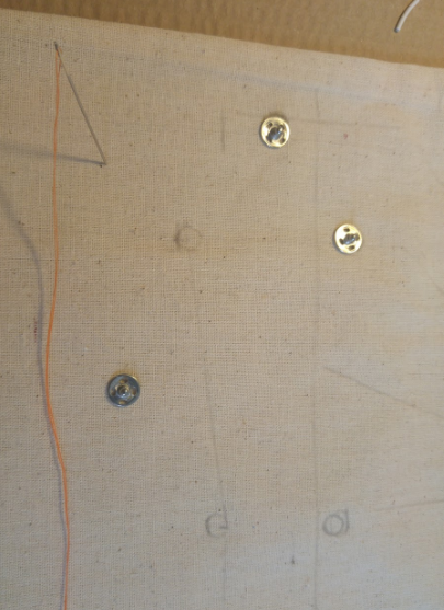
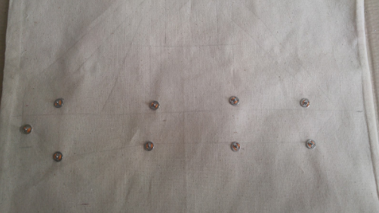
Draw with a pencil the position where the snap buttons will need to be attached to the textile bag, then sew them to the bag.
Remember that the photoresistor patch will need 3 snap buttons, whereas all other patches will need only two.
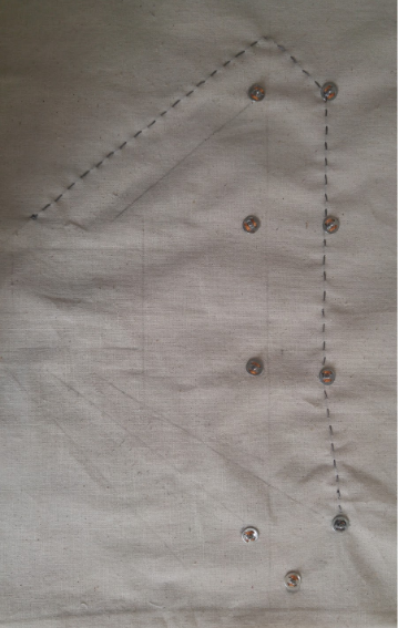
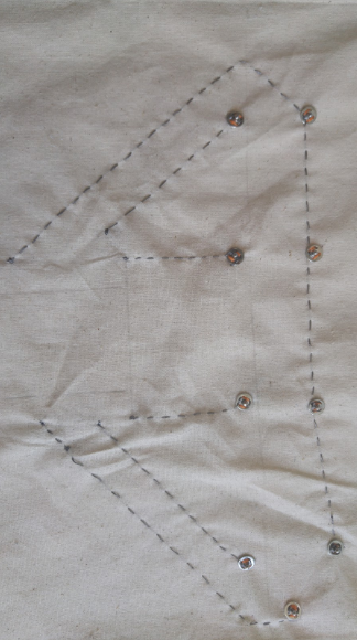
Étape 7 - Sew the conductive thread to the textile bag
Once all snap buttons are in place you need to make all necessary connections using the conductive thread
Start by sewing the wire that connects all negatives together.
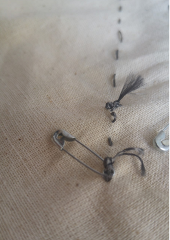
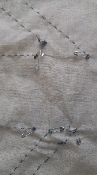
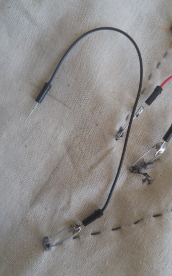
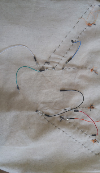
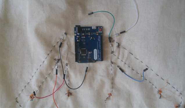
At the end of each conductive thread, you will need to attach a safety pin. This will be soldered to a jumper wire which will eventually connect the conductive thread to the Arduino board.
Notes et références
This tutorial has been developed as part of the I TECH project, co-financed by the Erasmus + program of the European Commission.
For more info contact us on info@digijeunes.com.
Published
 Français
 English
 Deutsch
 Español
 Italiano
 Português