(Page créée avec « Costruzione del robot ABC ») |
(Mise à jour pour être en accord avec la nouvelle version de la source de la page) |
||
| (44 révisions intermédiaires par 3 utilisateurs non affichées) | |||
| Ligne 1 : | Ligne 1 : | ||
| − | {{ | + | {{Tuto Details |
| − | | | + | |Main_Picture=Robot__ABC__en_bois_RobotTelecommande_09.jpg_4061.jpeg |
| − | | | + | |Description=<div class="mw-translate-fuzzy"> |
| − | | | + | Imparerete a costruire un piccolo robot controllato da telecomando. Questo robot è realizzato in legno con scheda elettronica (arduino uno) ed estensione di controllo per entrambi i motori. Video demo: https://www.youtube.com/watch?v=D8cRWR_TL4g |
| + | </div> | ||
| + | |Area=Electronics, Robotics | ||
|Type=Creation | |Type=Creation | ||
| − | |||
| − | |||
| − | |||
|Difficulty=Medium | |Difficulty=Medium | ||
| + | |Duration=1 | ||
| + | |Duration-type=day(s) | ||
|Cost=100 | |Cost=100 | ||
|Currency=EUR (€) | |Currency=EUR (€) | ||
| − | | | + | |Tags=Arduino, Robot, Bois, robotique, robotics |
| − | | | + | |SourceLanguage=fr |
| − | | | + | |Language=it |
| − | | | + | |IsTranslation=1 |
| + | }} | ||
| + | {{Introduction | ||
| + | |Introduction=Vous allez apprendre a construire le robot "ABC", un petit robot piloté par télécommande. Ce robot est construit en bois avec une carte électronique (Arduino Uno) et une extension de contrôle pour les deux moteurs. | ||
| + | }} | ||
| + | {{TutoVideo | ||
| + | |VideoType=Youtube | ||
| + | |VideoURLYoutube=https://www.youtube.com/watch?v=D8cRWR_TL4g | ||
| + | }} | ||
| + | {{Materials | ||
| + | |Prerequisites={{Prerequisites}} | ||
| + | |Tuto_Attachments={{Tuto Attachments | ||
| + | |Attachment=Robot-1.ino.pdf | ||
}} | }} | ||
| − | {{ | + | |ExternalAttachmentsLinks={{ExternalAttachmentsLinks |
| − | + | |ExternalAttachmentsLinks=https://framadrive.org/remote.php/webdav/Robot%20%22ABC%22%20V1%20Fran%C3%A7ais%20-%20English%20-%20Deutsch%20-%20Espa%C3%B1ol%20-%20Italiano/Code%20arduino%20-%20Arduino%20code%20-%20Arduino-Zahl%20-%20C%C3%B3digo%20Arduino%20-%20Codice%20Arduino/robot.ino | |
| − | |Material=1x | + | }} |
| + | |Material=1x spessore pannello in legno 5 mm 610 mm x 407 mm | ||
| + | <div class="mw-translate-fuzzy"> | ||
1x Arduino Uno | 1x Arduino Uno | ||
http://www.lextronic.fr/P4124-platine-arduino-uno-rev-3.html | http://www.lextronic.fr/P4124-platine-arduino-uno-rev-3.html | ||
| + | </div> | ||
1x Bandeau Led verte https://www.led-flexible.com/led-flexible-au-detail/1007-bande-led-unicolore-vert-non-etanche-de-25m-au-detail.html | 1x Bandeau Led verte https://www.led-flexible.com/led-flexible-au-detail/1007-bande-led-unicolore-vert-non-etanche-de-25m-au-detail.html | ||
| Ligne 54 : | Ligne 70 : | ||
*Clé Alen 1,5 mm (serrage des vis M3) | *Clé Alen 1,5 mm (serrage des vis M3) | ||
*pince de serrage (maintenir les entretoises et écrous) | *pince de serrage (maintenir les entretoises et écrous) | ||
| − | + | *Découpeuse laser ou scie sauteuse + perceuse | |
| − | |||
}} | }} | ||
| − | + | {{Tuto Step | |
| − | | | + | |Step_Title=Matériaux & Outils |
| + | |Step_Content====Matériaux=== | ||
| + | |||
| + | *1x planche de bois épaisseur 5mm 610mm X 407mm | ||
| + | |||
| + | *[https://www.gotronic.fr/art-arduino-uno-12420.htm 1x Arduino Uno] | ||
| + | |||
| + | *1x Bandeau Led verte https://www.led-flexible.com/led-flexible-au-detail/1007-bande-led-unicolore-vert-non-etanche-de-25m-au-detail.html | ||
| + | |||
| + | *1x alimentation pile (pour bandeau à led) https://www.led-flexible.com/alimentation-led-12-volts/408-boitier-piles-extra-plat-pour-ruban-led.html | ||
| + | |||
| + | *[https://www.gotronic.fr/cat-motoreducteurs-dagu-1953.htm 2x Moteurs DC] | ||
| + | |||
| + | *[https://www.gotronic.fr/art-shield-motor-2-x-1-a-dri0001-19343.htm 1x Motor Shield] | ||
| + | |||
| + | *[https://www.gotronic.fr/art-module-recepteur-ir-grove-101020016-18952.htm 1x capteur infrarouge] | ||
| + | *1x télécommande infrarouge (récupération DVD ou autre) | ||
| + | |||
| + | *2x supports de pile (6 pile LR6 1,5Volt) (Alimentation principale Arduino Uno) | ||
| + | |||
| + | *4x Piles 4,5Volts (2 pack montés en parallèle, chaque pack comporte 2 piles 4,5V montées en série) - (ça fait une alimentation sous 9V pour l’alimentation de puissance j’ai mis en parallèle pour avoir une plus longue autonomie) | ||
| + | |||
| + | *8x Écrous M4 http://www.bricovis.fr/std/ecrous-9.php#Grille | ||
| + | |||
| + | *8x vis M4 – 50 http://www.bricovis.fr/std/vis-tete-bombee-26.php#Grille | ||
| + | |||
| + | *4x Entretoise M4 http://fr.rs-online.com/web/p/entretoises/9141006/ | ||
| + | |||
| + | *1x roue pivotante http://www.leroymerlin.fr/v3/p/produits/roulette-pivotante-a-tige-filetee-diam-50-mm-e21351#&xtmc=roulette_pivotante_a_tige_filete&xtcr=1 | ||
| + | |||
| + | ===Outils=== | ||
| + | |||
| + | *Tournevis Cruciforme | ||
| + | *Clé Alen 1,5 mm (serrage des vis M3) | ||
| + | *pince de serrage (maintenir les entretoises et écrous) | ||
| + | *Découpeuse laser ou scie sauteuse + perceuse | ||
}} | }} | ||
| − | + | {{Tuto Step | |
| − | {{ | + | |Step_Title=Piani |
| − | + | |Step_Content=<div class="mw-translate-fuzzy"> | |
| − | |Step_Title= | + | Ecco i disegni di ogni parte per realizzare il robot con le dimensioni (in mm) |
| − | |Step_Content= | + | </div> |
| + | |||
| + | Scarica i file: https://framadrive.org/index.php/s/oHlHOqSsc18I4U1 | ||
| + | |||
| + | explication du dessin : | ||
| + | |||
| + | A quoi correspond le 1er chiffre avec X ? | ||
| + | |||
| + | le 1er chiffre correspond au nombre de fois ou la pièce est utilisé, par exemple 1x001 veut dire que la pièce 001 et utilisé une seule fois) - 001 correspond au nom du fichier utilisé soit le fichier 001.SLDPRT (solidworks) | ||
| + | |||
| + | Vous pouvez télécharger et ouvrir le fichier suivant : https://framadrive.org/s/7SHD4NXCia3dvFL (ce fichier nécessite l'installation du logiciel INKSCAPE téléchargeable avec ce lien : https://inkscape.org/fr/). | ||
| + | |||
| + | Dans ce fichier intitulé "Robot_ABC_V1.svg" figure les pièces à découper. | ||
| + | |||
| + | A quoi correspond le 3 chiffres? | ||
| + | |||
| + | Au nom des pièces | ||
| + | |||
| + | 001.SLDPRT = la base | ||
| + | |||
| + | 002.SLDPRT = les supports moteurs | ||
| + | |||
| + | 003.SLDPRT = les arcs | ||
| + | |||
| + | 004.SLDPRT = le dessus | ||
| + | |||
| + | 005.SLDPRT = les roues | ||
| + | |||
| + | 008.SLDPRT = Les vis M4 50mm | ||
| − | + | <div class="mw-translate-fuzzy"> | |
| + | Per utilizzare una macchina per taglio laser, vedere l' elenco dei FabLabs per trovare quello più vicino a voi: http://www.makery.info/map-labs/ | ||
| + | </div> | ||
Pour se servir d'une découpeuse laser voir la liste des FabLab pour trouver le plus proche de chez vous : http://www.makery.info/map-labs/ | Pour se servir d'une découpeuse laser voir la liste des FabLab pour trouver le plus proche de chez vous : http://www.makery.info/map-labs/ | ||
| − | |Step_Picture_00= | + | |Step_Picture_00=Robot_"ABC"_en_bois_RobotTelecommande_02b.jpg |
}} | }} | ||
| − | {{ | + | {{Tuto Step |
| − | |Step_Title= | + | |Step_Title=<div class="mw-translate-fuzzy"> |
| − | |Step_Content= | + | Supporto |
| + | </div> | ||
| + | |Step_Content=<div class="mw-translate-fuzzy"> | ||
| + | Iniziamo prendendo la base aggiungendo il supporto con la batteria collegata ai 3 LED verdi. | ||
| + | </div> | ||
| − | + | <div class="mw-translate-fuzzy"> | |
| + | Prendere 4 viti M4 e inserirle nei 4 fori e fissare 1 dado su ciascuna vite. | ||
| + | </div> | ||
|Step_Picture_00=RobotTelecommande 04a.jpg | |Step_Picture_00=RobotTelecommande 04a.jpg | ||
|Step_Picture_01=RobotTelecommande 04b.jpg | |Step_Picture_01=RobotTelecommande 04b.jpg | ||
|Step_Picture_02=RobotTelecommande 04c.jpg | |Step_Picture_02=RobotTelecommande 04c.jpg | ||
}} | }} | ||
| − | {{ | + | {{Tuto Step |
| − | |Step_Title= | + | |Step_Title=<div class="mw-translate-fuzzy"> |
| − | |Step_Content= | + | Sotto |
| + | </div> | ||
| + | |Step_Content=<div class="mw-translate-fuzzy"> | ||
| + | Inserire 4 viti M4 50mm con dadi e distanziali, quindi ruotare il gruppo per fissare il volante. | ||
| + | </div> | ||
|Step_Picture_00=RobotTelecommande 05a.jpg | |Step_Picture_00=RobotTelecommande 05a.jpg | ||
|Step_Picture_01=RobotTelecommande 05b.jpg | |Step_Picture_01=RobotTelecommande 05b.jpg | ||
}} | }} | ||
| − | {{ | + | {{Tuto Step |
| − | |Step_Title= | + | |Step_Title=<div class="mw-translate-fuzzy"> |
| − | |Step_Content= | + | Montaggio Base + Sotto |
| + | </div> | ||
| + | |Step_Content=<div class="mw-translate-fuzzy"> | ||
| + | Montare la base e il fondo avvitando ciascuna vite. | ||
| + | </div> | ||
|Step_Picture_00=RobotTelecommande 06a.jpg | |Step_Picture_00=RobotTelecommande 06a.jpg | ||
}} | }} | ||
| − | {{ | + | {{Tuto Step |
| − | |Step_Title= | + | |Step_Title=<div class="mw-translate-fuzzy"> |
| − | |Step_Content= | + | Elettronica ed elettronica |
| + | </div> | ||
| + | |Step_Content=<div class="mw-translate-fuzzy"> | ||
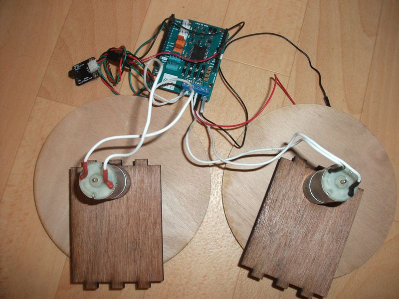
| + | Fissare il motore ai lati in legno. | ||
| + | </div> | ||
|Step_Picture_00=RobotTelecommande 07a.jpg | |Step_Picture_00=RobotTelecommande 07a.jpg | ||
}} | }} | ||
| − | {{ | + | {{Tuto Step |
| − | |Step_Title= | + | |Step_Title=Montaggio finale |
| − | |Step_Content= | + | |Step_Content=<div class="mw-translate-fuzzy"> |
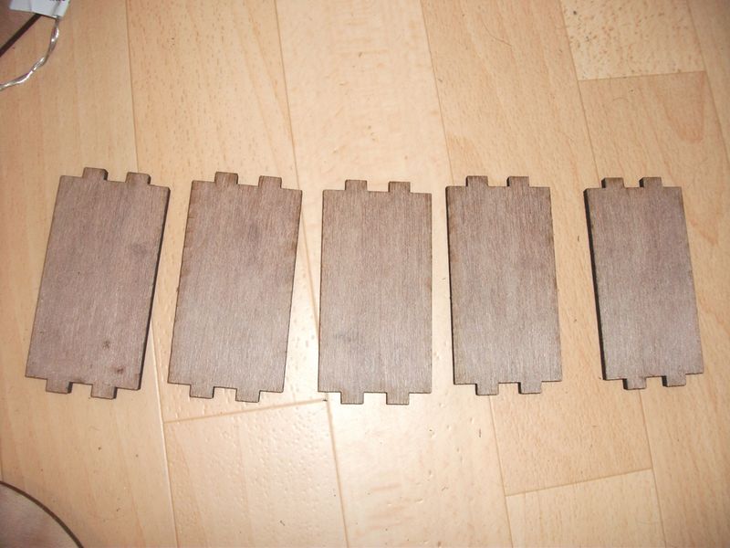
| + | Montare i pannelli di arrotondamento e i pannelli sul lato motore nell' illustrazione al punto 4. | ||
| + | </div> | ||
|Step_Picture_00=RobotTelecommande 08.jpg | |Step_Picture_00=RobotTelecommande 08.jpg | ||
}} | }} | ||
| − | {{ | + | {{Tuto Step |
| − | |Step_Title= | + | |Step_Title=<div class="mw-translate-fuzzy"> |
| + | Panoramica robotizzata | ||
| + | </div> | ||
| + | |Step_Content=Prochaine évolution mettre un capteur ultrason pour détection et évitement d’obstacle et un suiveur de ligne. | ||
|Step_Picture_00=RobotTelecommande 09.jpg | |Step_Picture_00=RobotTelecommande 09.jpg | ||
|Step_Picture_01=RobotTelecommande 10.jpg | |Step_Picture_01=RobotTelecommande 10.jpg | ||
| Ligne 108 : | Ligne 211 : | ||
|Step_Picture_03=Presentation_robot_abc.jpg | |Step_Picture_03=Presentation_robot_abc.jpg | ||
}} | }} | ||
| − | {{ | + | {{Notes |
| − | + | |Notes= | |
| − | | | ||
| − | |||
| − | |||
}} | }} | ||
| − | {{ | + | {{PageLang |
| − | |||
| − | |||
}} | }} | ||
| − | {{ | + | {{Tuto Status |
| − | + | |Complete=Published | |
| − | |Complete= | ||
}} | }} | ||
| + | {{Separator}} | ||
Version actuelle datée du 22 février 2023 à 12:50
Imparerete a costruire un piccolo robot controllato da telecomando. Questo robot è realizzato in legno con scheda elettronica (arduino uno) ed estensione di controllo per entrambi i motori. Video demo: https://www.youtube.com/watch?v=D8cRWR_TL4g
Introduction
Youtube
Matériaux
1x spessore pannello in legno 5 mm 610 mm x 407 mm
1x Arduino Uno http://www.lextronic.fr/P4124-platine-arduino-uno-rev-3.html
1x Bandeau Led verte https://www.led-flexible.com/led-flexible-au-detail/1007-bande-led-unicolore-vert-non-etanche-de-25m-au-detail.html
1x alimentation pile (pour bandeau à led) https://www.led-flexible.com/alimentation-led-12-volts/408-boitier-piles-extra-plat-pour-ruban-led.html
2x Moteurs DC http://www.lextronic.fr/P29728-motor-pack-dc25.html
1x Motor Shield http://www.lextronic.fr/P26224-platine-motor-shield-rev3-pour-arduino.html
1x capteur infrarouge 1x télécommande infrarouge http://www.robotshop.com/eu/fr/kit-infrarouge-pour-arduino.html
2x supports de pile (6 pile LR6 1,5Volt) (Alimentation principale Arduino Uno)
4x Piles 4,5Volts (2 pack montés en parallèle, chaque pack comporte 2 piles 4,5V montées en série) - (ça fait une alimentation sous 9V pour l’alimentation de puissance j’ai mis en parallèle pour avoir une plus longue autonomie)
8x Écrous M4 http://www.bricovis.fr/std/ecrous-9.php#Grille
8x vis M4 – 50 http://www.bricovis.fr/std/vis-tete-bombee-26.php#Grille
4x Entretoise M4 http://fr.rs-online.com/web/p/entretoises/9141006/
1x roue pivotante http://www.leroymerlin.fr/v3/p/produits/roulette-pivotante-a-tige-filetee-diam-50-mm-e21351#&xtmc=roulette_pivotante_a_tige_filete&xtcr=1
Outils
- Tournevis Cruciforme
- Clé Alen 1,5 mm (serrage des vis M3)
- pince de serrage (maintenir les entretoises et écrous)
- Découpeuse laser ou scie sauteuse + perceuse
Étape 1 - Matériaux & Outils
Matériaux
- 1x planche de bois épaisseur 5mm 610mm X 407mm
- 1x Bandeau Led verte https://www.led-flexible.com/led-flexible-au-detail/1007-bande-led-unicolore-vert-non-etanche-de-25m-au-detail.html
- 1x alimentation pile (pour bandeau à led) https://www.led-flexible.com/alimentation-led-12-volts/408-boitier-piles-extra-plat-pour-ruban-led.html
- 1x capteur infrarouge
- 1x télécommande infrarouge (récupération DVD ou autre)
- 2x supports de pile (6 pile LR6 1,5Volt) (Alimentation principale Arduino Uno)
- 4x Piles 4,5Volts (2 pack montés en parallèle, chaque pack comporte 2 piles 4,5V montées en série) - (ça fait une alimentation sous 9V pour l’alimentation de puissance j’ai mis en parallèle pour avoir une plus longue autonomie)
- 8x Écrous M4 http://www.bricovis.fr/std/ecrous-9.php#Grille
- 8x vis M4 – 50 http://www.bricovis.fr/std/vis-tete-bombee-26.php#Grille
- 4x Entretoise M4 http://fr.rs-online.com/web/p/entretoises/9141006/
- 1x roue pivotante http://www.leroymerlin.fr/v3/p/produits/roulette-pivotante-a-tige-filetee-diam-50-mm-e21351#&xtmc=roulette_pivotante_a_tige_filete&xtcr=1
Outils
- Tournevis Cruciforme
- Clé Alen 1,5 mm (serrage des vis M3)
- pince de serrage (maintenir les entretoises et écrous)
- Découpeuse laser ou scie sauteuse + perceuse
Étape 2 - Piani
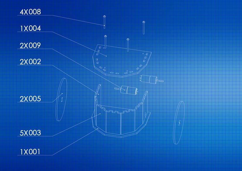
Ecco i disegni di ogni parte per realizzare il robot con le dimensioni (in mm)
Scarica i file: https://framadrive.org/index.php/s/oHlHOqSsc18I4U1
explication du dessin :
A quoi correspond le 1er chiffre avec X ?
le 1er chiffre correspond au nombre de fois ou la pièce est utilisé, par exemple 1x001 veut dire que la pièce 001 et utilisé une seule fois) - 001 correspond au nom du fichier utilisé soit le fichier 001.SLDPRT (solidworks)
Vous pouvez télécharger et ouvrir le fichier suivant : https://framadrive.org/s/7SHD4NXCia3dvFL (ce fichier nécessite l'installation du logiciel INKSCAPE téléchargeable avec ce lien : https://inkscape.org/fr/).
Dans ce fichier intitulé "Robot_ABC_V1.svg" figure les pièces à découper.
A quoi correspond le 3 chiffres?
Au nom des pièces
001.SLDPRT = la base
002.SLDPRT = les supports moteurs
003.SLDPRT = les arcs
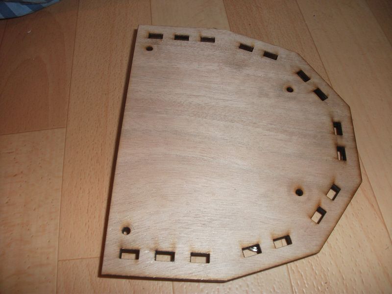
004.SLDPRT = le dessus
005.SLDPRT = les roues
008.SLDPRT = Les vis M4 50mm
Per utilizzare una macchina per taglio laser, vedere l' elenco dei FabLabs per trovare quello più vicino a voi: http://www.makery.info/map-labs/
Pour se servir d'une découpeuse laser voir la liste des FabLab pour trouver le plus proche de chez vous : http://www.makery.info/map-labs/
Étape 3 -
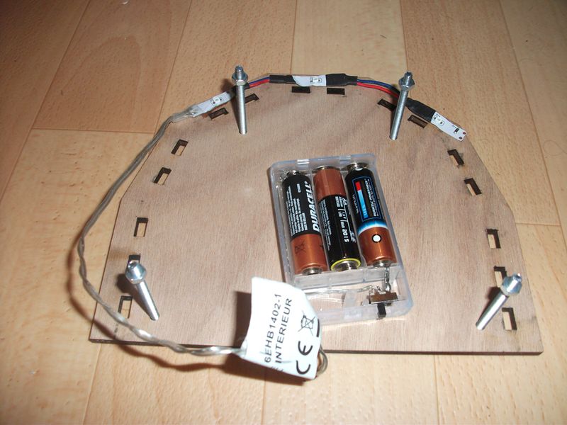
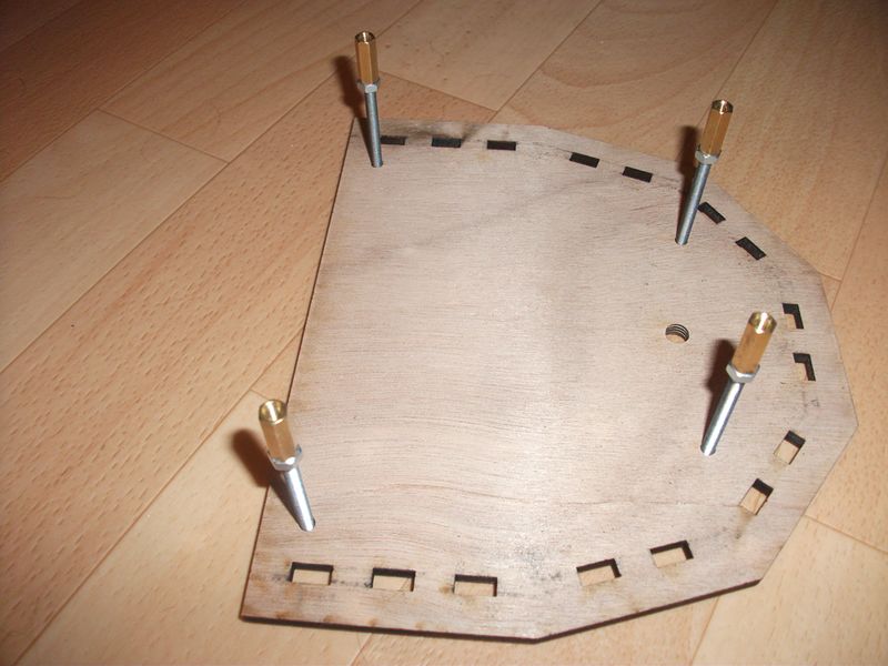
Supporto
Supporto
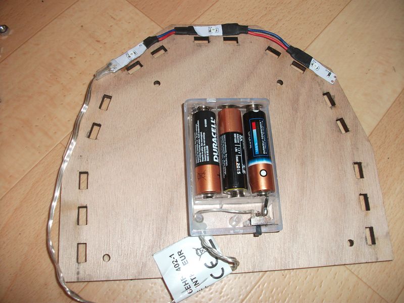
Iniziamo prendendo la base aggiungendo il supporto con la batteria collegata ai 3 LED verdi.
Prendere 4 viti M4 e inserirle nei 4 fori e fissare 1 dado su ciascuna vite.
Étape 4 -
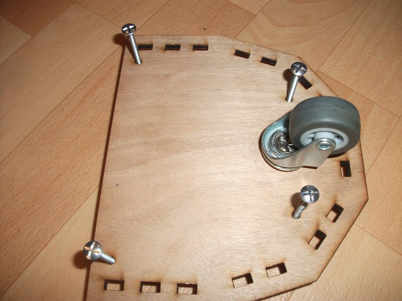
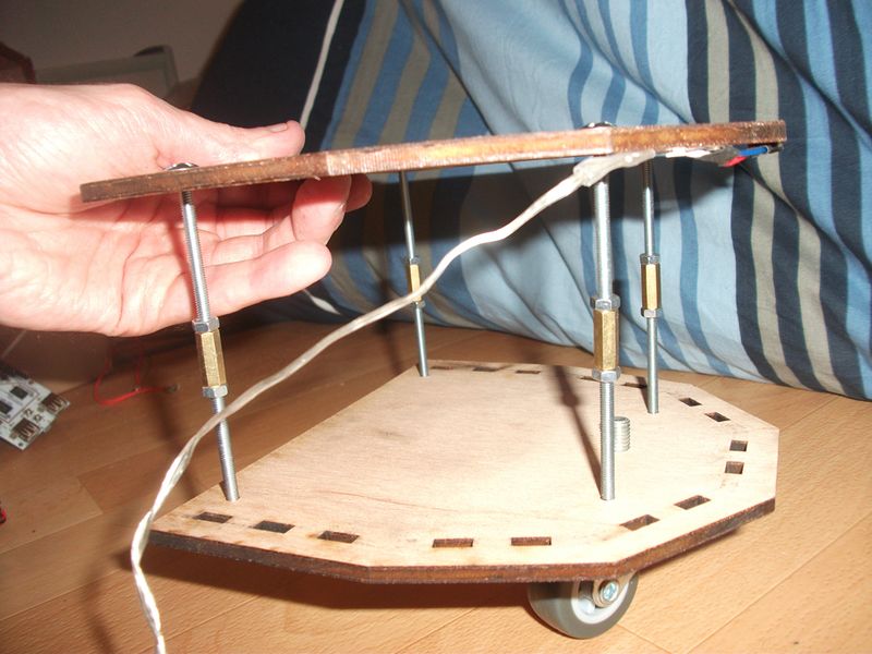
Sotto
Sotto
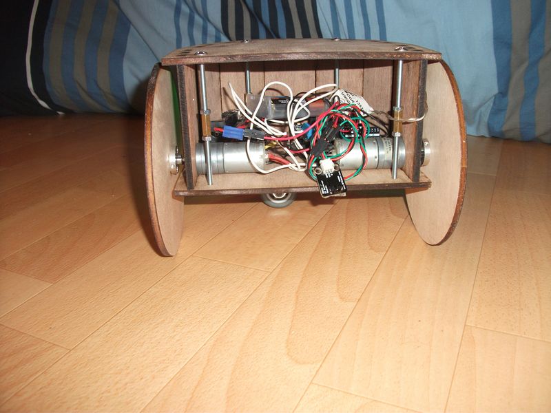
Inserire 4 viti M4 50mm con dadi e distanziali, quindi ruotare il gruppo per fissare il volante.
Étape 7 - Montaggio finale
Montare i pannelli di arrotondamento e i pannelli sul lato motore nell' illustrazione al punto 4.
Étape 8 -
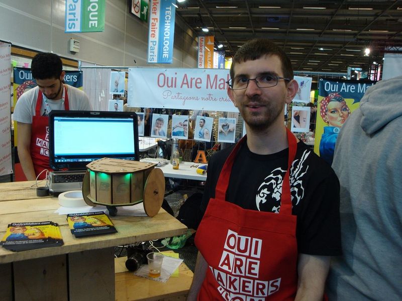
Panoramica robotizzata
Panoramica robotizzata
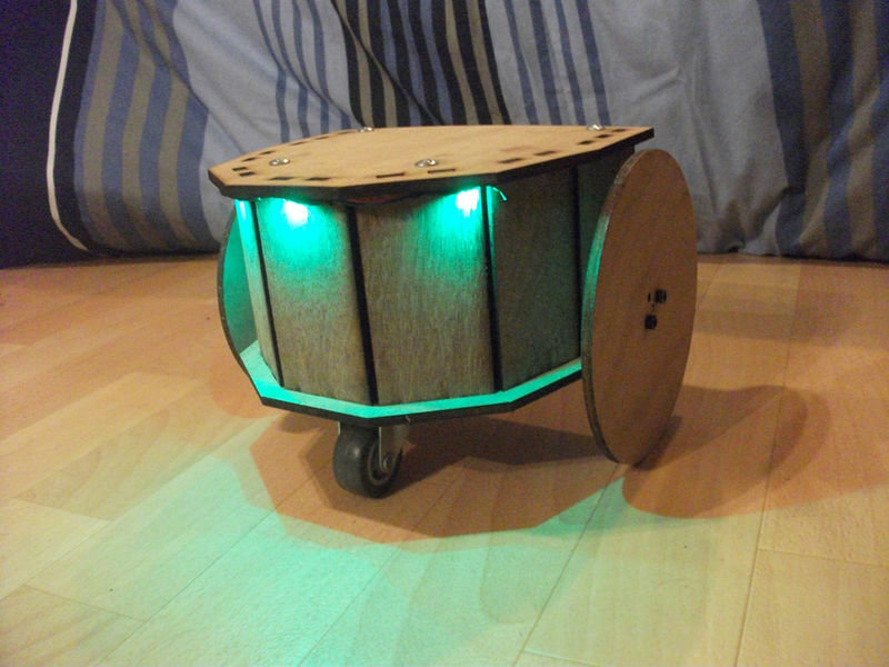
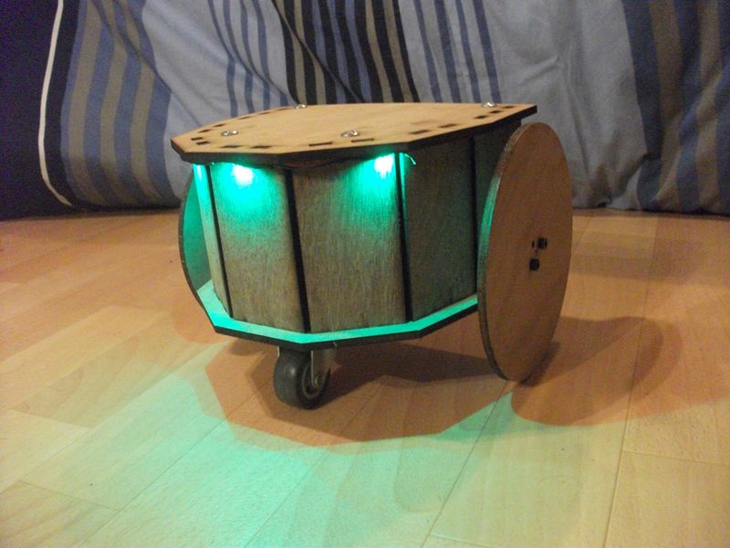
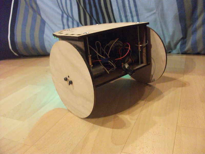
Prochaine évolution mettre un capteur ultrason pour détection et évitement d’obstacle et un suiveur de ligne.
Published
 Français
 English
 Deutsch
 Español
 Italiano
 Português