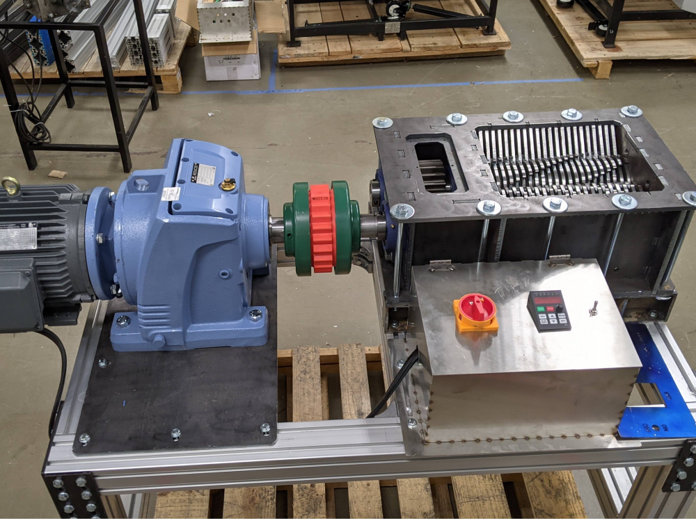
preciousplastic, recycling, Open Source, plastic, shredderPP_Shredder_Pro_PXL_20211105_232745273.jpgCreation
Introduction
Required skills:
Basic tools
Steel tapping
Matériaux
Outils
Étape 1 - Tools
Hammer
(punch) for knocking out leftover metal slugs
Files
Mallet
Socket wrench( 2x)
Vice Grips
Files
Tape measure
Screwdriver
Marker
Angle Grinder
Bandsaw
Étape 2 - Table Parts
Parts Needed:
Aluminum Extrusion
Profile
Length (mm)
Quantity
8080
520
4
8080
600
4
8080
1200
2
4080
520
1
4080
455
1
data-sheets-value="{"1":2,"2":"Corner Plates"}"
Étape 3 - Table Construction - Legs
Tools
XX Socket Wrench
Screwdriver
Parts
4x 8080*600mm
2x 8080*1200mm
4x Side Plates
32x + 13x T nuts
32x Washers
32x M8x16mm Bolts
Steps
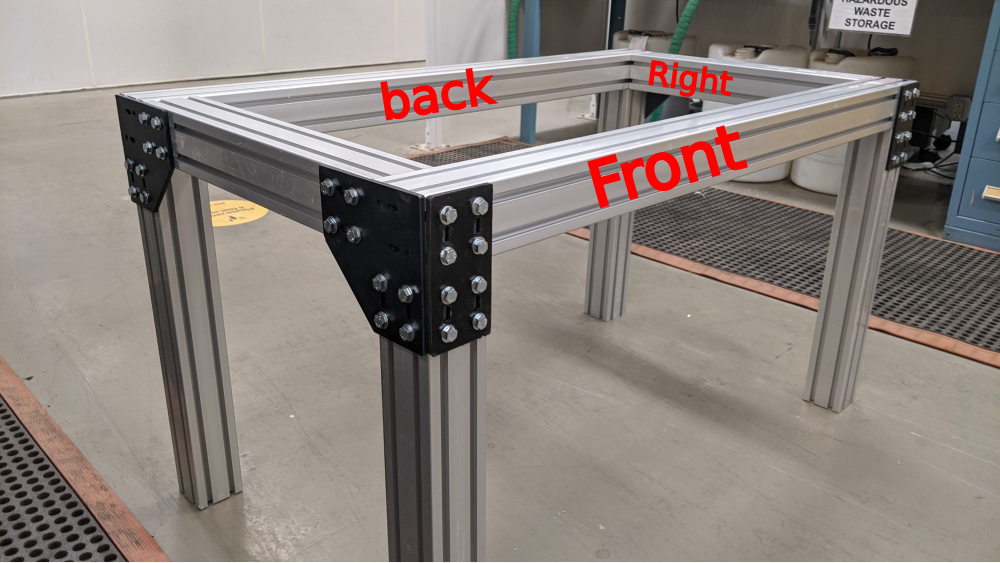
Lay one 1200mm beam horizontally in your workspace. Add a 600mm beam perpendicular at each end, forming a staple shape. (see image 5 for final shape reference)
Using 8 total washers, slide 2 at a time into each rail at the corner, approximating the hole pattern on the side plates. (image 2)
Using a screwdriver to position the T-nuts, add an M8x16 Bolt and washer through the side plate into each T nut. (images 3 and 4)
Secure with a socket wrench. Repeat on the other side of the 1200mm beam.
You now have a staple shape. Repeat.
It is important to now denote which one of these will be your front and which will be your back. Just pick.
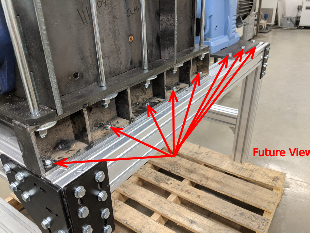
On the BACK staple, top side, inner track, add 8 T-nuts for later use. [image 6 shows what they'll hold in a future step]
On the Front staple, top side, inner track add 5
*make sure these stay in place as you rotate the leg pieces and continue to build in following steps.
Étape 4 - Table Construction - Side Joints
Tools
XX Socket Wrench
Screwdriver
Parts
2x 8080*520mm
4x Corner Plates
44x T nuts
32x Washers
32x M8x16mm Bolts
Steps
Stand one leg unit upward, so you can see down the 1200mm section. Slide 4 T-nuts total (2 in each rail) up to the corner joint. (image 2)
SPECIAL STEP: on the 1200mm beam, opposite side from where the side plate was installed - Slide 2 nuts into each of the rails. These will be used in a future step. Repeat on the other 1200mm beam.
Attach the side plate (image 3) using 4 M8x16 Bolts with 4 washers.
NOTE: the 45° side should face the "bottom" of the eventual table.
Repeat on the remaining three 600mm legs.
NOTE: ensure that each corner plate mirrors each other across the 1200mm beam axis. They should be facing the same direction and away from the side plate from the previous step.
Slide 8 total T-nuts into a 520mm beam. They should be split in half, 4 at one end, and 4 at the other. (Image 4)
SPECIAL STEP: On only ONE of the 520mm beams, add 4 T-nuts, 2 in each rail on the opposite side that you used for Step 5.
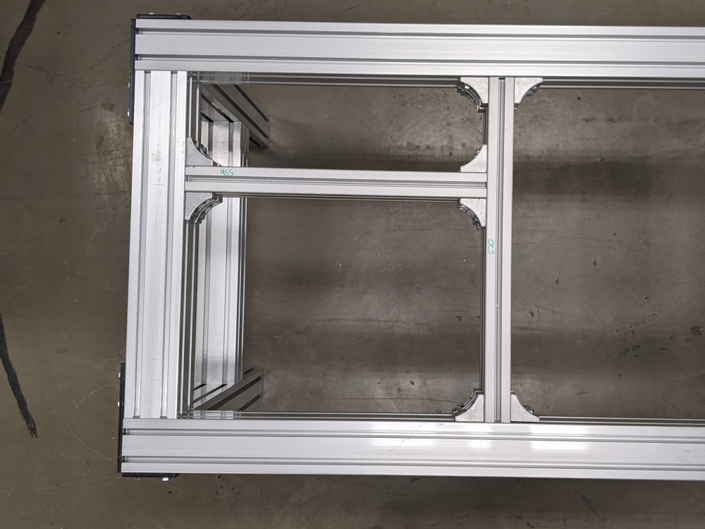
Combine the two "staple" sections by adding the 520mm beam (pre-loaded with T-nuts) using the same M8x16mm, washer combination as before. (image 5)
Repeat on the other side. (image 6)
You should now have a very solid table base!
Étape 5 - Table Construction - Side Braces
Tools
XX Socket Wrench
Screwdriver
Parts
2x 8080*520mm
8x Brackets
16x T nuts
16x Washers
16x M8x20mm Bolts
*A quick note about bracket orientation. In image 2 you will see that the brackets are not the same on both sides. Here we have flipped one, so you can see the difference. One of the holes sits atop a raised lip, while the other is flush. The raised lip hole is closer to the brackets outside edge. The flush hole is farther from the outside edge. This matters for order of operations. When installing, you must install in the flush hole first, and the hole with the raised lip second. If you do it in reverse the bolt will block access to the other hole. :)
Steps
Slide 4 nuts into the 520mm beam (2 in each rail).
Attach the 4 brackets loosely using M8x20mm bolts and washers. (image 3)
Note the orientation of the holes. All 4 bolts should go in flush holes, not raised lip holes. (figure 4)
With the table flipped on its end, position the 520mm beam in place, and slide 2 T-nuts in the rails to meet the brackets. Secure with same M8x20 bolt washer combo.
Repeat this process on the other side of the 520mm beam.
Repeat steps 1-4 on the opposite side of table.
Étape 6 - Table Construction - Center Struts
Tools
XX Socket Wrench
Screwdriver
Parts
1x 4080*520mm
1x 4080*455mm
16 Brackets
20x T nuts
32x Washers
32x M8x16mm Bolts
*Construction note: Until the very end, keep ALL of these bolt joints LOOSE. They will need to slide around to get everything in place. Once the location has been set, then you can tighten them down.
Steps
Insert 4 T-nuts (2 in each rail) on one side of the 520mm 4080 (image1 )
For both beams, attach brackets (using the flush hole) at all 8 corners. (image 2)
Arrange the beams so the 520mm beam is vertical, and the 455mm beam is horizontal, intersecting near the middle of the 520mm beam on the left hand side.
Loosely attach the horizontal beam to the vertical beam. (images 3 and 4)
Remember all those T-nuts we hid in the frame in step 4? Now we are going to connect this sub-assembly to them.
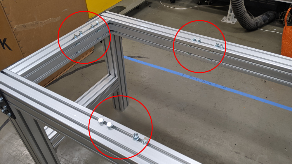
Place 4 bolt/washer combos at each of the 3 locations designated in image 5.
Drop the sub-assembly into the table frame, and loosely connect the brackets into the pre-loaded T-nuts
This is easier with 2 people.
You only need 1 bolt at each of the three locations to hold the weight of the sub-assembly.
After those first three bolts are in, you can easily go back and connect the others.
Étape 7 - Shredder Box Layout 1
Tools
none
Parts
1110.02 - Bottom Plate Box
1110.03 - Fixed Blades plate 1
1110.04 - Fixed Blades plate 2
1110.05 - Bearing Side Plate 1
1110.06 - Bearing Side Plate 2
1110.07 - Bearing Side Plate 3
*this is much easier with two people to hold the plates before they are locked into position. It is also heavy metal, and a dropped plate is enough to cause injury.
Steps
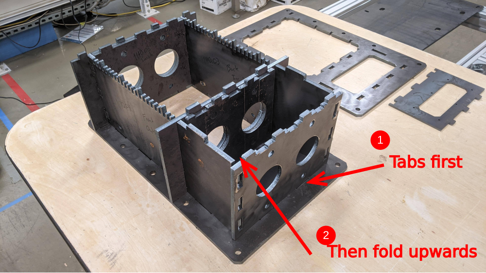
Layout the parts as seen in image 1, ensuring that the fixed blade plates are mirrored.
Teeth should be pointing away from each other.
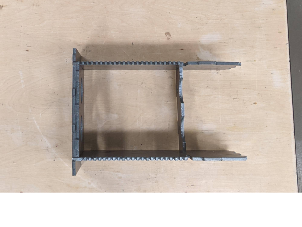
Fold up both plates so the teeth point upwards while your helper inserts the tabs from pieces 1110.07 and 1110.05. You should now have a 4 walled box as seen in image 2.
Fold up plate 1110.06 to meet the left end of the box.
CAREFULLY slide the bottom plate underneath this sub-assembly, aligning the tabs until it drops into place.
Étape 8 - Shredder Box Layout 2
Tools
none
Parts
1110.08 - Bearing Side Plate 4
1110.09 - Bearing Side Plate 5
1110.10 - Bearing Side Plate 6
1110.11 - Gear Plate
1110.01 - Top Plate
Steps
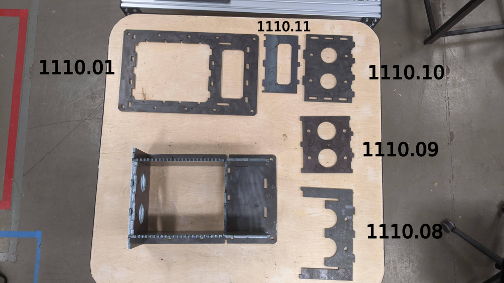
Layout the remaining pies as seen in image 1.
Slide plate 1110.08 directly on top of piece 1110.07
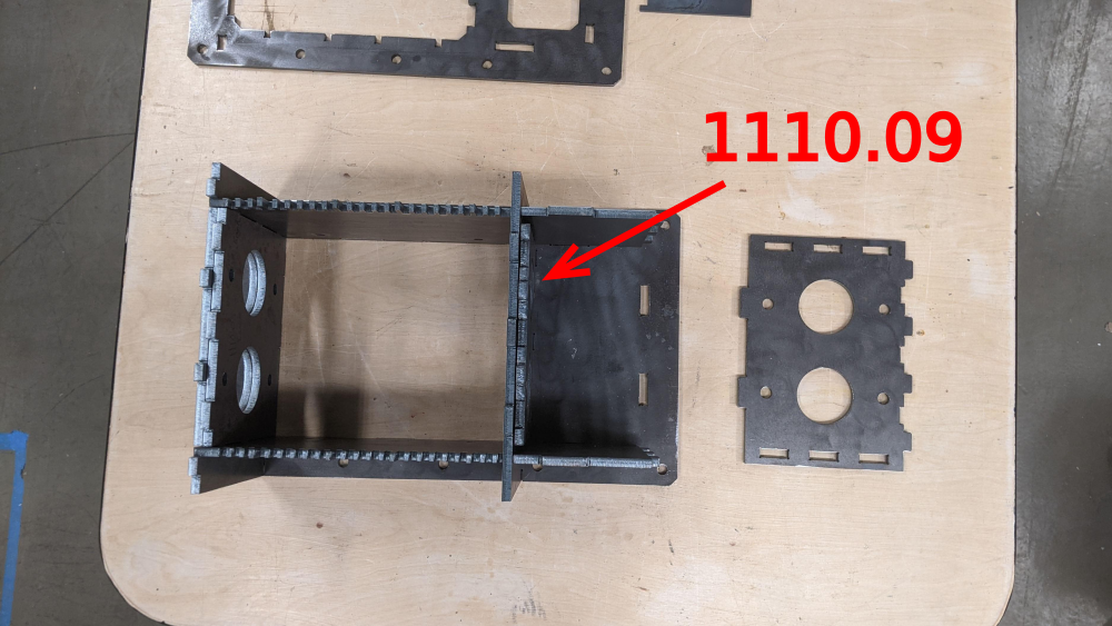
Drop in plate 1110.09 directly next to 1110.07/.08 in the open tabs.
Place the bottom tabs of plate 1110.10 into the bottom plate, and then fold the plate upwards into place.
Place plate 1110.11 on top as seen in image 5.
Place plate 1110.01 on top, securing the entire box in place.
*Note - in the next steps, you will dismantle these last few steps, but it is important to understand how the box comes together.
Étape 9 - Tapping bearing holes 1
Tools
M16 x 2 Tap
Tapping oil(optional but recommended)
2 medium/large clamps
Parts
4 M16 x 40mm Socket head cap bolts
4 M16 washers
Shredder box assembly
Steps
Remove the top plate from Step 8 above.
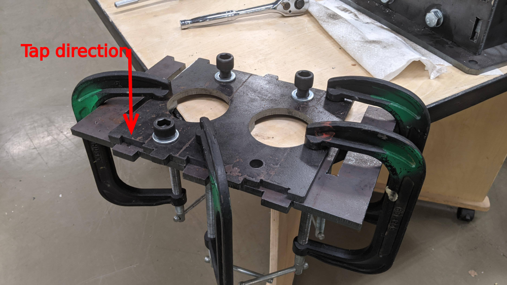
Secure parts 1110.05/.06 (Left end of shredder box) using 2 C-clamps.
*Be sure to leave yourself room to turn the tap.
*It is important to have a tight fit. If your steel parts have burs or scratches that prevent a tight connection, remove those first!
For each hole, tap both plates in one consecutive operation. Remove burrs and clean the hole.
Check the hole by securing the M16 bolts.
Étape 10 - Tapping bearing holes 2
Tools
M16 x 2 Tap
Tapping oil(optional but recommended)
2 medium/large clamps
Parts
4 M16 x 40mm Socket head cap bolts
4 M16 washers
Shredder box assembly
Steps
If not already perfectly aligned, ensure that the bearing holes on parts 1110.08/.09 are perfectly aligned. This will ensure the tapping process goes smoothly and the parts are in a straight line.
Tightly secure parts 1110.08/.09 with C-clamps while they are still inside the shredder box.
Lift the two plates out with the clamps.
Repeat the tapping procedure as before, ensuring that you begin the tap on the face of part 1110.09. Tap all 4 holes.
Add bolts to the top two holes.
[image 4] Breakout piece 1110.07 from the shredder box. Align it with the clamped assembly, ensuring that the circle openings are perfectly matched.
Clamp piece 1110.07 to the newly tapped assembly. [image 5]
Continuing from the pre-tapped holes of piece 1110.09, tap into piece 1110.07.
Remove all bolts, and return the shredder box plates to their appropriate location.
Étape 11 - Tapping bearing holes 3
Tools
M16 x 2 Tap
Tapping oil(optional but recommended)
2 large bar clamps
Parts
4 M16 x 30mm Socket head cap bolts
4 M16 washers
Shredder box assembly
Steps
Secure plate 1110.10. (This can be done in place, or by removing it and attaching it to the table)
Tap all 4 holes.
In the photo, we used hex heads as opposed to button cap sockets.
Étape 12 - Shaft Assembly Preparation
Tools
Industrial Band Saw (roll-in, horizontal band, etc.)
Benchtop Grinder
Handheld Angle Grinder
Metal files
Parts
???? Nuts
Shaft 1:
23x 1130.01 13-Teeth Blade
23x 1/4" spacer
23x ???? thin spacers
Shaft 2:
2x 1120.01 6-Teeth Blade 1
2x 1120.02 6-Teeth Blade 2
2x 1120.03 6-Teeth Blade 3
2x 1120.04 6-Teeth Blade 4
2x 1120.05 6-Teeth Blade 5
2x 1120.06 6-Teeth Blade 6
2x 1120.07 6-Teeth Blade 7
2x 1120.08 6-Teeth Blade 8
2x 1120.09 6-Teeth Blade 9
2x 1120.010 6-Teeth Blade 10
2x 1120.011 6-Teeth Blade 11
2x 1120.011 6-Teeth Blade 12
23x 1/4" spacer
23x ???? thin spacers
Steps
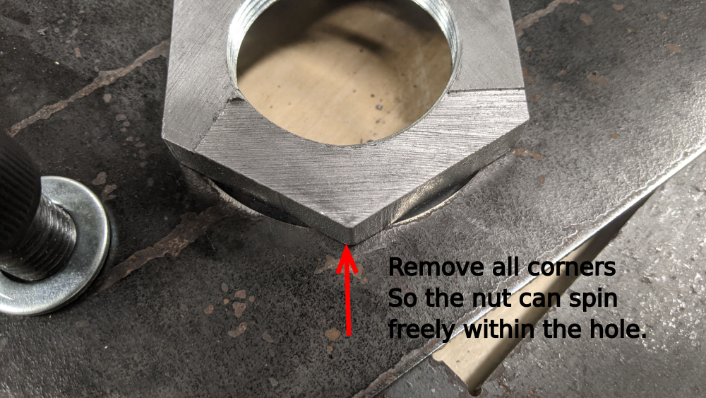
Split the nut in half with whatever method you can :)
we used a roll-in saw, but a horizontal band saw, or a hand saw could be used.
Grind or cut the corners off of the half nut until it fits within the shredder box hole openings. (repeat for all 4 nuts)
layout your parts according to the pictures
Étape 13 - secure the gearbox to the table
Parts
4x 5/8 x 2 3/4 Hex bolts
4x 5/8 washers
4x 5/8 lock nuts
Commentaires
ennone0Published
×
Erreur de saisie dans le nom du tutoriel
Vous avez entré un nom de page invalide, avec un ou plusieurs caractères suivants :
< > @ ~ : * € £ ` + = / \ | [ ] { } ; ? #
Connexion
Pas encore enregistré ? Créez un compte pour profiter de toutes les fonctionnalités du service !


 Français
 English
 Deutsch
 Español
 Italiano
 Português