| Ligne 444 : | Ligne 444 : | ||
}} | }} | ||
{{Tuto Step | {{Tuto Step | ||
| − | |Step_Title=<translate>Shredder Box Risers</translate> | + | |Step_Title=<translate>Shredder Box Risers (part 1)</translate> |
|Step_Content=<translate>====Tools==== | |Step_Content=<translate>====Tools==== | ||
Welding machine | Welding machine | ||
| Ligne 452 : | Ligne 452 : | ||
2x Riser assemblies. For each: | 2x Riser assemblies. For each: | ||
| − | * 2x end caps | + | *2x end caps |
| − | * top plate | + | *top plate |
| − | * bottom plate | + | *bottom plate |
| − | * large side plate | + | *large side plate |
| − | * 4 support plates | + | *4 support plates |
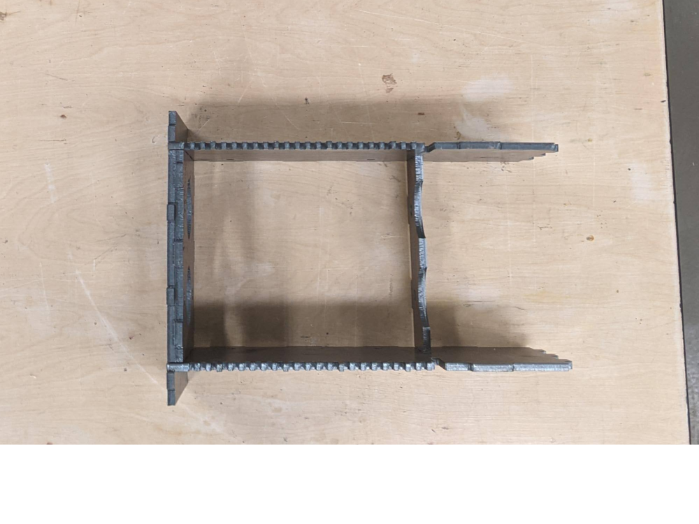
| − | + | ==== Steps ==== | |
| − | + | ||
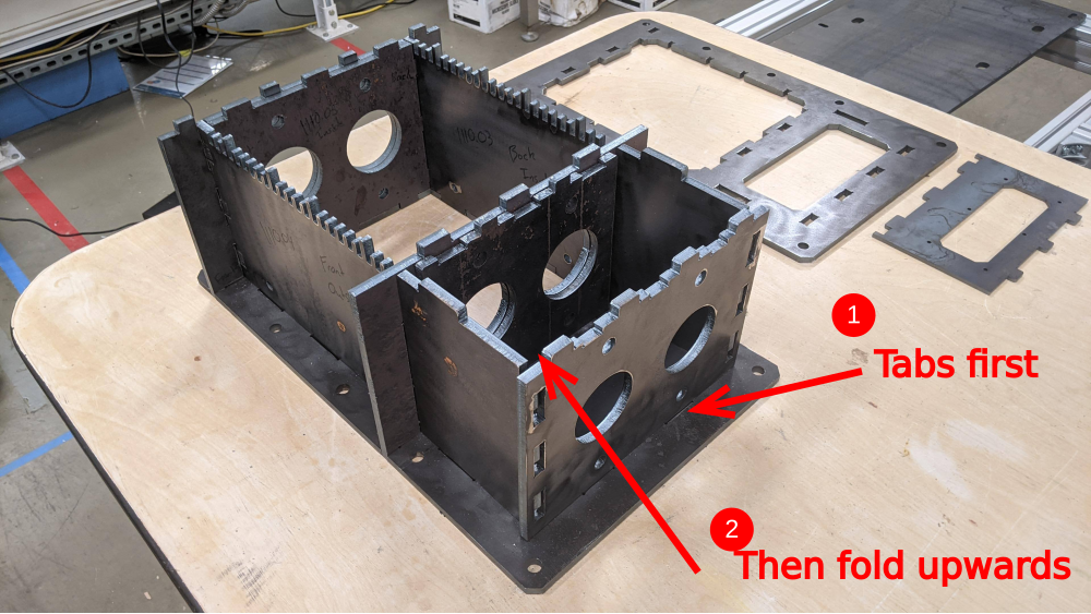
| − | + | *Layout the box pieces as seen in Image 1, ensuring that the bolts holes are aligned. | |
| − | + | *Fold the pieces into place and secure with 2 C-Clamps | |
| − | + | *Tack weld the box together | |
| − | + | *Insert the 4 spacers evenly, ensuring not to block any of the bolt holes in the top and bottom plates. | |
| − | + | *Apply pressure to the box with C-Clamps, ensuring the support pieces remain vertical. | |
| + | *Weld in place. | ||
| + | *Repeat for the other support.</translate> | ||
|Step_Picture_00=PP_Shredder_Pro_PXL_20211030_201538616_1_.jpg | |Step_Picture_00=PP_Shredder_Pro_PXL_20211030_201538616_1_.jpg | ||
|Step_Picture_01=PP_Shredder_Pro_PXL_20211030_201829800.jpg | |Step_Picture_01=PP_Shredder_Pro_PXL_20211030_201829800.jpg | ||
| Ligne 470 : | Ligne 472 : | ||
|Step_Picture_03=PP_Shredder_Pro_PXL_20211030_204609285.jpg | |Step_Picture_03=PP_Shredder_Pro_PXL_20211030_204609285.jpg | ||
|Step_Picture_04=PP_Shredder_Pro_PXL_20211102_213043448.jpg | |Step_Picture_04=PP_Shredder_Pro_PXL_20211102_213043448.jpg | ||
| + | }} | ||
| + | {{Tuto Step | ||
| + | |Step_Title=<translate>Shredder Box Risers (part 2)</translate> | ||
| + | |Step_Content=<translate>====Tools==== | ||
| + | 1/2"Socket Wrench | ||
| + | ====Parts==== | ||
| + | 2x Riser assemblies. | ||
| + | |||
| + | 10x M8x16mm Bolts/ Washers | ||
| + | |||
| + | (T-nuts should all already have been installed) | ||
| + | |||
| + | ==== Steps ==== | ||
| + | |||
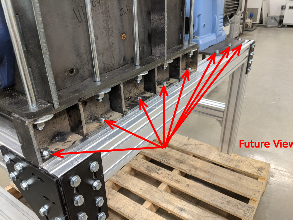
| + | # Slide the horizontal aluminum extrusion from step XX to about 1 foot from the back of the table base. | ||
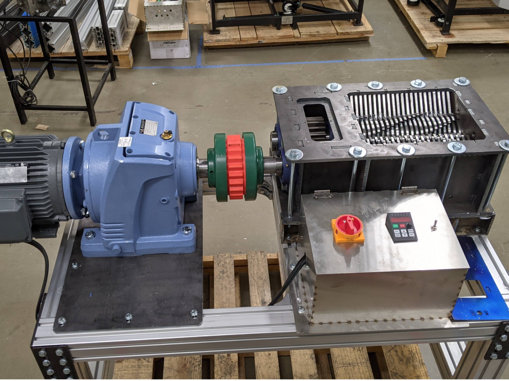
| + | # Position a riser on this beam, aligning the in-set T-nuts to the bolts holes on the riser. The larger holes on the riser should be on top. (image 1) | ||
| + | # Position the the other riser on the back of the table in the same way. (image 2) | ||
| + | # (with a friend) lift the shredder box onto the risers. (ignore the shafts in the picture, we'll add those next) | ||
| + | |||
| + | <br /></translate> | ||
| + | |Step_Picture_00=PP_Shredder_Pro_PXL_20211118_220130542.jpg | ||
| + | |Step_Picture_01=PP_Shredder_Pro_PXL_20211118_220227628.jpg | ||
| + | |Step_Picture_02=PP_Shredder_Pro_PXL_20211118_220751621.jpg | ||
}} | }} | ||
{{Tuto Step | {{Tuto Step | ||
| Ligne 558 : | Ligne 583 : | ||
{{Tuto Step | {{Tuto Step | ||
|Step_Title=<translate>Shaft Assembly Preparation (long shaft) and install</translate> | |Step_Title=<translate>Shaft Assembly Preparation (long shaft) and install</translate> | ||
| − | |Step_Content=<translate>====Parts==== | + | |Step_Content=<translate>==== Tools ==== |
| + | Chain, nylon strap | ||
| + | |||
| + | ====Parts==== | ||
2 Nut halves from step 12 | 2 Nut halves from step 12 | ||
| Ligne 570 : | Ligne 598 : | ||
24x thin spacers | 24x thin spacers | ||
| − | + | ==== Steps ==== | |
#Add a nut to the short end of the shaft. | #Add a nut to the short end of the shaft. | ||
| Ligne 585 : | Ligne 613 : | ||
#Mesh the two shafts together '''outside the box'''. | #Mesh the two shafts together '''outside the box'''. | ||
| − | #With a partner, lift the double shaft assembly as far into the box as you can, leaving room to escape your hands. | + | #With a partner, lift the double shaft assembly as far into the box as you can, leaving room to escape your hands. |
#Thread a chain, rope, nylon strap, or anything that can drop below both shafts and that can serve as a handle to lift the assembly up and into its final position. | #Thread a chain, rope, nylon strap, or anything that can drop below both shafts and that can serve as a handle to lift the assembly up and into its final position. | ||
#Unthread the rope assist seat the shaft nuts into the openings in both ends of the shaft box. | #Unthread the rope assist seat the shaft nuts into the openings in both ends of the shaft box. | ||
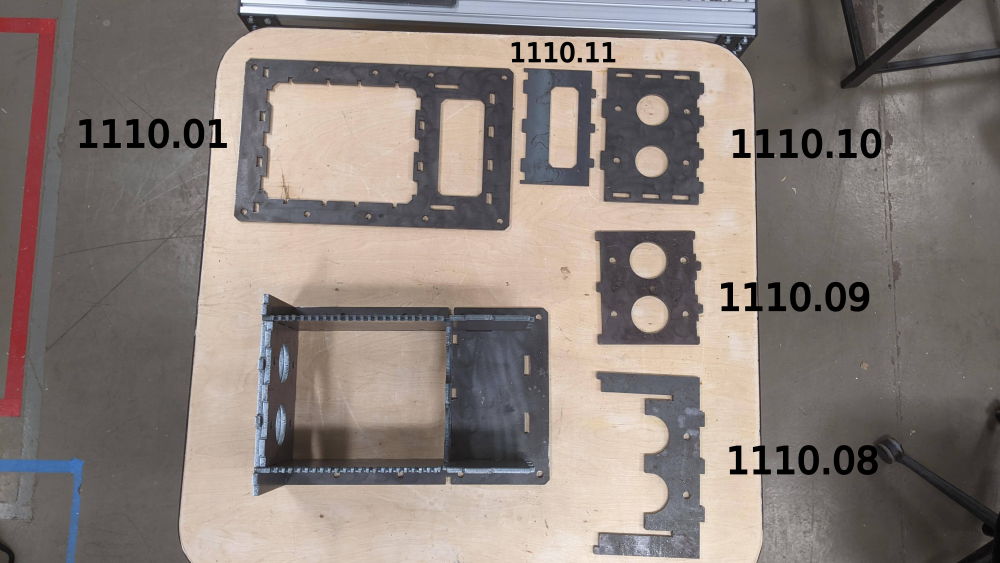
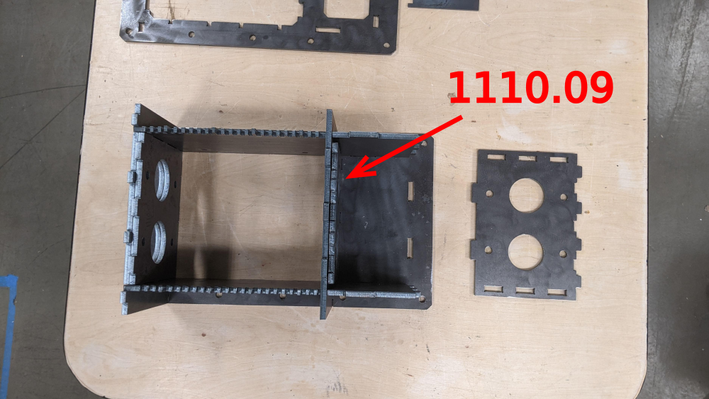
| − | #Replace pieces 1110.08 and 1110.09 | + | #Replace pieces 1110.08 and 1110.09 |
<br /></translate> | <br /></translate> | ||
| Ligne 597 : | Ligne 625 : | ||
|Step_Picture_04=PP_Shredder_Pro_PXL_20211029_180345072.jpg | |Step_Picture_04=PP_Shredder_Pro_PXL_20211029_180345072.jpg | ||
|Step_Picture_05=PP_Shredder_Pro_PXL_20211029_180413042.jpg | |Step_Picture_05=PP_Shredder_Pro_PXL_20211029_180413042.jpg | ||
| + | }} | ||
| + | {{Tuto Step | ||
| + | |Step_Title=<translate>Bearing Prep</translate> | ||
| + | |Step_Content=<translate>==== Tools ==== | ||
| + | Bench Vise | ||
| + | |||
| + | Angle Grinder with flap disk | ||
| + | |||
| + | (Digital Caliper helps) | ||
| + | |||
| + | ==== Parts ==== | ||
| + | 2 Bearings | ||
| + | |||
| + | ==== Steps ==== | ||
| + | As is, the bearings and gears '''''do not fit''''' inside the shredder box. about 1/8" of an inch of material must be removed from the bearing sleeve. | ||
| + | |||
| + | # Measure the depth of the sleeve before grinding. Use the thumb screw on your digital caliper to lock this distance. | ||
| + | # Using an angle grinder, remove the necessary material. | ||
| + | # Recheck the distance, ensuring you've removed enough. (***** number to be exact?)</translate> | ||
| + | |Step_Picture_00=PP_Shredder_Pro_PXL_20211029_203711597.jpg | ||
| + | |Step_Picture_01=PP_Shredder_Pro_PXL_20211030_211313319.jpg | ||
| + | |Step_Picture_02=PP_Shredder_Pro_PXL_20211030_212403001_exported_9880.jpg | ||
| + | |Step_Picture_03=PP_Shredder_Pro_PXL_20211030_212100945.jpg | ||
| + | }} | ||
| + | {{Tuto Step | ||
| + | |Step_Title=<translate>Shredder box final assembly (Step 1)</translate> | ||
| + | |Step_Content=<translate>==== Tools ==== | ||
| + | <br /> | ||
| + | |||
| + | ==== Parts ==== | ||
| + | |||
| + | ==== Steps ====</translate> | ||
}} | }} | ||
{{Tuto Step | {{Tuto Step | ||
Version du 19 novembre 2021 à 01:53
This tutorial documents the build process of Precious Plastic Pro Shredder, as supplied by Citizen Scientific for the North American context.

Difficulté
Difficile
Durée
5 jour(s)
Catégories
Machines & Outils, Recyclage & Upcycling, Robotique
Coût
5000 USD ($)
Sommaire
- 1 Introduction
- 2 Étape 1 - Tools
- 3 Étape 2 - Table Parts
- 4 Étape 3 - Table Construction - Legs
- 5 Étape 4 - Table Construction - Side Joints
- 6 Étape 5 - Table Construction - Side Braces
- 7 Étape 6 - Table Construction - Center Struts
- 8 Étape 7 - Shredder Box Layout 1
- 9 Étape 8 - Shredder Box Layout 2
- 10 Étape 9 - Tapping bearing holes 1
- 11 Étape 10 - Tapping bearing holes 2
- 12 Étape 11 - Tapping bearing holes 3
- 13 Étape 12 - Shredder Box Risers (part 1)
- 14 Étape 13 - Shredder Box Risers (part 2)
- 15 Étape 14 - Shaft Assembly Preparation 1
- 16 Étape 15 - Shaft Assembly Preparation 2 (short shaft)
- 17 Étape 16 - Shaft Assembly Preparation (long shaft) and install
- 18 Étape 17 - Bearing Prep
- 19 Étape 18 - Shredder box final assembly (Step 1)
- 20 Étape 19 - secure the gearbox to the table
- 21 Commentaires
Introduction
Required skills:
Basic tools
Metal tapping
Power tools
Welding
Matériaux
Outils
Étape 1 - Tools
Hammer
(punch) for knocking out leftover metal slugs
Files
Mallet
Socket wrench( 2x)
Vice Grips
Files
Tape measure
Screwdriver
Marker
Angle Grinder
Bandsaw
Étape 2 - Table Parts
Parts Needed:
Aluminum Extrusion
| Profile | Length (mm) | Quantity |
|---|---|---|
| 8080 | 520 | 4 |
| 8080 | 600 | 4 |
| 8080 | 1200 | 2 |
| 4080 | 520 | 1 |
| 4080 | 455 | 1 |
| data-sheets-value="{"1":2,"2":"Corner Plates"}"
Étape 3 - Table Construction - LegsToolsXX Socket Wrench Screwdriver Parts4x 8080*600mm 2x 8080*1200mm 4x Side Plates 32x + 13x T nuts 32x Washers 32x M8x16mm Bolts Steps
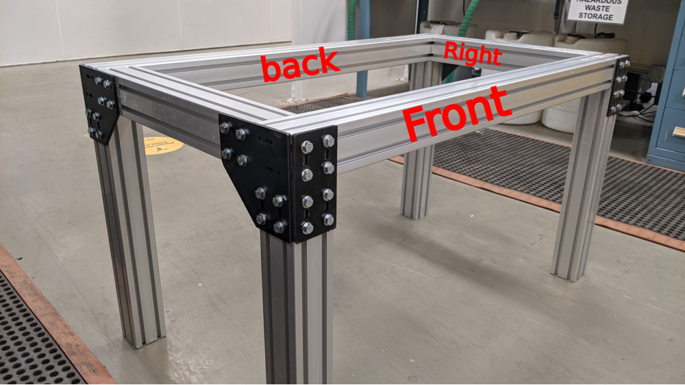
You now have a staple shape. Repeat. It is important to now denote which one of these will be your front and which will be your back. Just pick.
*make sure these stay in place as you rotate the leg pieces and continue to build in following steps.
   
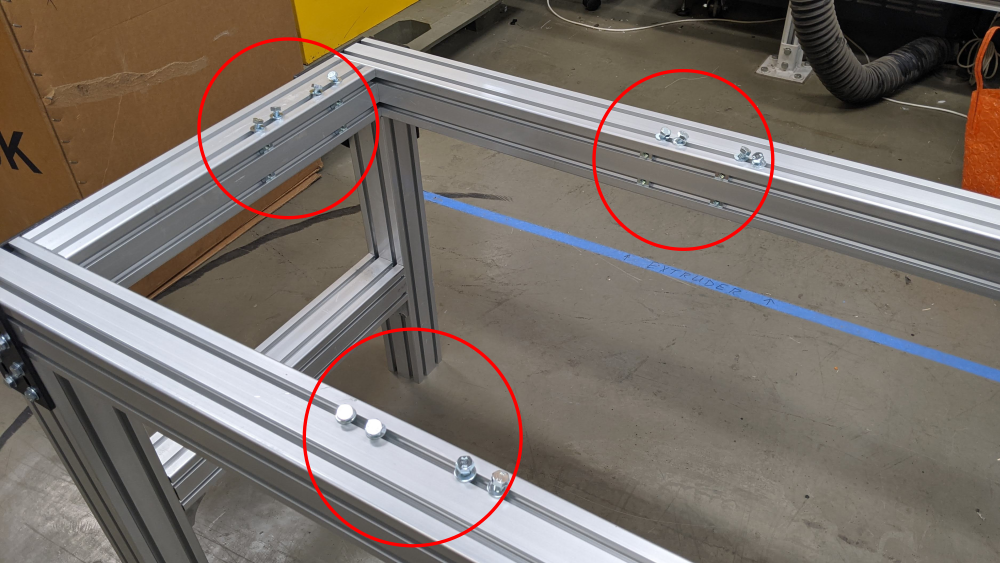
Étape 4 - Table Construction - Side JointsTools1/2" Socket Wrench Screwdriver Parts2x 8080*520mm 4x Corner Plates 32 + 12 + 4 (48x) T nuts 32x Washers 32x M8x16mm Bolts Steps
You should now have a very solid table base! 

Étape 5 - Table Construction - Side BracesTools1/2" Socket Wrench Screwdriver Parts2x 8080*520mm 8x Brackets 16x T nuts 16x Washers 16x M8x20mm Bolts
Steps
     
Étape 6 - Table Construction - Center StrutsTools1/2" Socket Wrench Screwdriver Parts1x 4080*520mm 1x 4080*455mm 16 Brackets
32x Washers 32x M8x16mm Bolts
Steps


Étape 7 - Shredder Box Layout 1Toolsnone Parts1110.02 - Bottom Plate Box 1110.03 - Fixed Blades plate 1 1110.04 - Fixed Blades plate 2 1110.05 - Bearing Side Plate 1 1110.06 - Bearing Side Plate 2 1110.07 - Bearing Side Plate 3
Steps

 
Étape 8 - Shredder Box Layout 2Toolsnone Parts1110.08 - Bearing Side Plate 4 1110.09 - Bearing Side Plate 5 1110.10 - Bearing Side Plate 6 1110.11 - Gear Plate 1110.01 - Top Plate Steps
*Note - in the next steps, you will dismantle these last few steps, but it is important to understand how the box comes together.
 
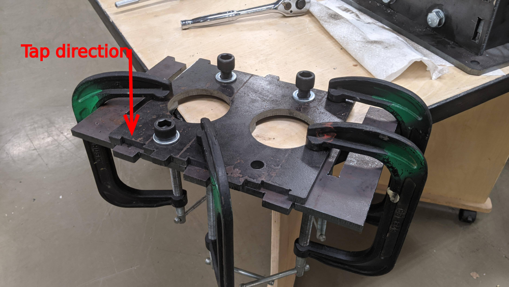
Étape 9 - Tapping bearing holes 1ToolsM16 x 2 Tap Tapping oil(optional but recommended) 2 medium/large clamps Parts4 M16 x 40mm Socket head cap bolts 4 M16 washers Shredder box assembly
Steps
     
Étape 10 - Tapping bearing holes 2ToolsM16 x 2 Tap Tapping oil(optional but recommended) 2 medium/large clamps Parts4 M16 x 40mm Socket head cap bolts 4 M16 washers Shredder box assembly Steps


Étape 11 - Tapping bearing holes 3ToolsM16 x 2 Tap Tapping oil(optional but recommended) 2 large bar clamps Parts4 M16 x 30mm Socket head cap bolts 4 M16 washers Shredder box assembly Steps

Étape 12 - Shredder Box Risers (part 1)ToolsWelding machine C-Clamps Parts2x Riser assemblies. For each:
Steps
    
Étape 13 - Shredder Box Risers (part 2)Tools1/2"Socket Wrench Parts2x Riser assemblies. 10x M8x16mm Bolts/ Washers (T-nuts should all already have been installed) Steps
  
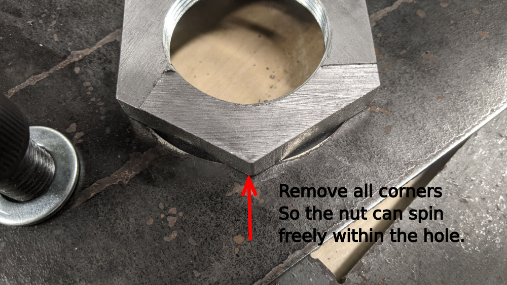
Étape 14 - Shaft Assembly Preparation 1ToolsIndustrial Band Saw (roll-in, horizontal band, etc.) Benchtop Grinder Handheld Angle Grinder Metal files Parts2 Nuts
Steps
 
  
Étape 15 - Shaft Assembly Preparation 2 (short shaft)Parts2 Nut halves from previous step
2x 1120.01 6-Teeth Blade 1 2x 1120.02 6-Teeth Blade 2 2x 1120.03 6-Teeth Blade 3 2x 1120.04 6-Teeth Blade 4 2x 1120.05 6-Teeth Blade 5 2x 1120.06 6-Teeth Blade 6 2x 1120.07 6-Teeth Blade 7 2x 1120.08 6-Teeth Blade 8 2x 1120.09 6-Teeth Blade 9 2x 1120.010 6-Teeth Blade 10 2x 1120.011 6-Teeth Blade 11 1x 1120.011 6-Teeth Blade 12 22x 1/4" spacer 22x thin spacers
     
Étape 16 - Shaft Assembly Preparation (long shaft) and installToolsChain, nylon strap Parts2 Nut halves from step 12
22x 1130.01 13-Teeth Blade 24x 1/4" spacer 24x thin spacers Steps
You now have 2 complete shafts ready to drop into your shredder box. This is very difficult to do alone, and can also be hazardous due to the heavy weight and sharp edges. To install:
     
Étape 17 - Bearing PrepToolsBench Vise Angle Grinder with flap disk (Digital Caliper helps) Parts2 Bearings StepsAs is, the bearings and gears do not fit inside the shredder box. about 1/8" of an inch of material must be removed from the bearing sleeve.
   
Étape 18 - Shredder box final assembly (Step 1)Tools
PartsSteps
Étape 19 - secure the gearbox to the tableParts4x 5/8 x 2 3/4 Hex bolts 4x 5/8 washers 4x 5/8 lock nuts
Published |


 Français
 English
 Deutsch
 Español
 Italiano
 Português