| Ligne 17 : | Ligne 17 : | ||
{{ {{tntn|Introduction}} | {{ {{tntn|Introduction}} | ||
|Introduction=This simple diy analog synth is part of an upcoming series of little projects, that can be used to learn about basic electronics, while having fun with the result. As the synth has a chip socket, you will be able to change the pitch range of the sound through different capacitors. Just change it on the fly, or keep it and build several of these synths. | |Introduction=This simple diy analog synth is part of an upcoming series of little projects, that can be used to learn about basic electronics, while having fun with the result. As the synth has a chip socket, you will be able to change the pitch range of the sound through different capacitors. Just change it on the fly, or keep it and build several of these synths. | ||
| + | |||
| + | You can use sound effect software like http://rakarrack.sourceforge.net/. Check out the video! | ||
There will be build-up tutorials in the future. Have fun! | There will be build-up tutorials in the future. Have fun! | ||
}} | }} | ||
{{ {{tntn|TutoVideo}} | {{ {{tntn|TutoVideo}} | ||
| − | |VideoType= | + | |VideoType=Youtube |
| + | |VideoURLYoutube=https://www.youtube.com/watch?v=mG9HKZbo0q8&feature=youtu.be | ||
}} | }} | ||
{{ {{tntn|Materials}} | {{ {{tntn|Materials}} | ||
| Ligne 47 : | Ligne 50 : | ||
{{ {{tntn|Separator}}}} | {{ {{tntn|Separator}}}} | ||
{{ {{tntn|Tuto Step}} | {{ {{tntn|Tuto Step}} | ||
| − | |Step_Title=Mark Prototype | + | |Step_Title=Mark Prototype Board |
|Step_Content= | |Step_Content= | ||
|Step_Picture_00=ASKotec_Tutorials_-_DIY_Simple_analog_synth_SimpleSynth_LookMumNoCompi_bb.jpg | |Step_Picture_00=ASKotec_Tutorials_-_DIY_Simple_analog_synth_SimpleSynth_LookMumNoCompi_bb.jpg | ||
| Ligne 53 : | Ligne 56 : | ||
}} | }} | ||
{{ {{tntn|Tuto Step}} | {{ {{tntn|Tuto Step}} | ||
| − | |Step_Title= | + | |Step_Title=Solder Basic Components To Board |
|Step_Content= | |Step_Content= | ||
|Step_Picture_00=ASKotec_Tutorials_-_DIY_Simple_analog_synth_SimpleSynth_LookMumNoComputer_4_SolderComponents.jpg | |Step_Picture_00=ASKotec_Tutorials_-_DIY_Simple_analog_synth_SimpleSynth_LookMumNoComputer_4_SolderComponents.jpg | ||
| Ligne 59 : | Ligne 62 : | ||
}} | }} | ||
{{ {{tntn|Tuto Step}} | {{ {{tntn|Tuto Step}} | ||
| − | |Step_Title= | + | |Step_Title=Bridge Potentiometer Channels |
|Step_Content= | |Step_Content= | ||
|Step_Picture_00=ASKotec_Tutorials_-_DIY_Simple_analog_synth_SimpleSynth_LookMumNoComputer_6_PotentiometerBridge.jpg | |Step_Picture_00=ASKotec_Tutorials_-_DIY_Simple_analog_synth_SimpleSynth_LookMumNoComputer_6_PotentiometerBridge.jpg | ||
}} | }} | ||
{{ {{tntn|Tuto Step}} | {{ {{tntn|Tuto Step}} | ||
| − | |Step_Title= | + | |Step_Title=Wire 1 |
|Step_Content= | |Step_Content= | ||
|Step_Picture_00=ASKotec_Tutorials_-_DIY_Simple_analog_synth_SimpleSynth_LookMumNoComputer_7_Wire1.jpg | |Step_Picture_00=ASKotec_Tutorials_-_DIY_Simple_analog_synth_SimpleSynth_LookMumNoComputer_7_Wire1.jpg | ||
}} | }} | ||
{{ {{tntn|Tuto Step}} | {{ {{tntn|Tuto Step}} | ||
| − | |Step_Title= | + | |Step_Title=Wire 2 |
|Step_Content= | |Step_Content= | ||
|Step_Picture_00=ASKotec_Tutorials_-_DIY_Simple_analog_synth_SimpleSynth_LookMumNoComputer_8_Wire2.jpg | |Step_Picture_00=ASKotec_Tutorials_-_DIY_Simple_analog_synth_SimpleSynth_LookMumNoComputer_8_Wire2.jpg | ||
}} | }} | ||
{{ {{tntn|Tuto Step}} | {{ {{tntn|Tuto Step}} | ||
| − | |Step_Title= | + | |Step_Title=Wire 3 |
|Step_Content= | |Step_Content= | ||
|Step_Picture_00=ASKotec_Tutorials_-_DIY_Simple_analog_synth_SimpleSynth_LookMumNoComputer_9_Wire3.jpg | |Step_Picture_00=ASKotec_Tutorials_-_DIY_Simple_analog_synth_SimpleSynth_LookMumNoComputer_9_Wire3.jpg | ||
}} | }} | ||
{{ {{tntn|Tuto Step}} | {{ {{tntn|Tuto Step}} | ||
| − | |Step_Title= | + | |Step_Title=Wire 4 |
|Step_Content= | |Step_Content= | ||
|Step_Picture_00=ASKotec_Tutorials_-_DIY_Simple_analog_synth_SimpleSynth_LookMumNoComputer_10_Wire4.jpg | |Step_Picture_00=ASKotec_Tutorials_-_DIY_Simple_analog_synth_SimpleSynth_LookMumNoComputer_10_Wire4.jpg | ||
}} | }} | ||
{{ {{tntn|Tuto Step}} | {{ {{tntn|Tuto Step}} | ||
| − | |Step_Title= | + | |Step_Title=Wire 5 |
|Step_Content= | |Step_Content= | ||
|Step_Picture_00=ASKotec_Tutorials_-_DIY_Simple_analog_synth_SimpleSynth_LookMumNoComputer_11_Wire5.jpg | |Step_Picture_00=ASKotec_Tutorials_-_DIY_Simple_analog_synth_SimpleSynth_LookMumNoComputer_11_Wire5.jpg | ||
}} | }} | ||
{{ {{tntn|Tuto Step}} | {{ {{tntn|Tuto Step}} | ||
| − | |Step_Title= | + | |Step_Title=Solder component legs |
|Step_Content= | |Step_Content= | ||
|Step_Picture_00=ASKotec_Tutorials_-_DIY_Simple_analog_synth_SimpleSynth_LookMumNoComputer_12_ResistorLeg.jpg | |Step_Picture_00=ASKotec_Tutorials_-_DIY_Simple_analog_synth_SimpleSynth_LookMumNoComputer_12_ResistorLeg.jpg | ||
}} | }} | ||
{{ {{tntn|Tuto Step}} | {{ {{tntn|Tuto Step}} | ||
| − | |Step_Title= | + | |Step_Title=Solder DC Connector |
|Step_Content= | |Step_Content= | ||
|Step_Picture_00=ASKotec_Tutorials_-_DIY_Simple_analog_synth_SimpleSynth_LookMumNoComputer_13_DCWire.jpg | |Step_Picture_00=ASKotec_Tutorials_-_DIY_Simple_analog_synth_SimpleSynth_LookMumNoComputer_13_DCWire.jpg | ||
}} | }} | ||
{{ {{tntn|Tuto Step}} | {{ {{tntn|Tuto Step}} | ||
| − | |Step_Title= | + | |Step_Title=Create Safety Strap |
|Step_Content= | |Step_Content= | ||
|Step_Picture_00=ASKotec_Tutorials_-_DIY_Simple_analog_synth_SimpleSynth_LookMumNoComputer_14_SafetyWire.jpg | |Step_Picture_00=ASKotec_Tutorials_-_DIY_Simple_analog_synth_SimpleSynth_LookMumNoComputer_14_SafetyWire.jpg | ||
}} | }} | ||
{{ {{tntn|Tuto Step}} | {{ {{tntn|Tuto Step}} | ||
| − | |Step_Title= | + | |Step_Title=Prepare moveable elements |
|Step_Content= | |Step_Content= | ||
|Step_Picture_00=ASKotec_Tutorials_-_DIY_Simple_analog_synth_SimpleSynth_LookMumNoComputer_15_PlugNPlay.jpg | |Step_Picture_00=ASKotec_Tutorials_-_DIY_Simple_analog_synth_SimpleSynth_LookMumNoComputer_15_PlugNPlay.jpg | ||
Version du 1 octobre 2019 à 13:19
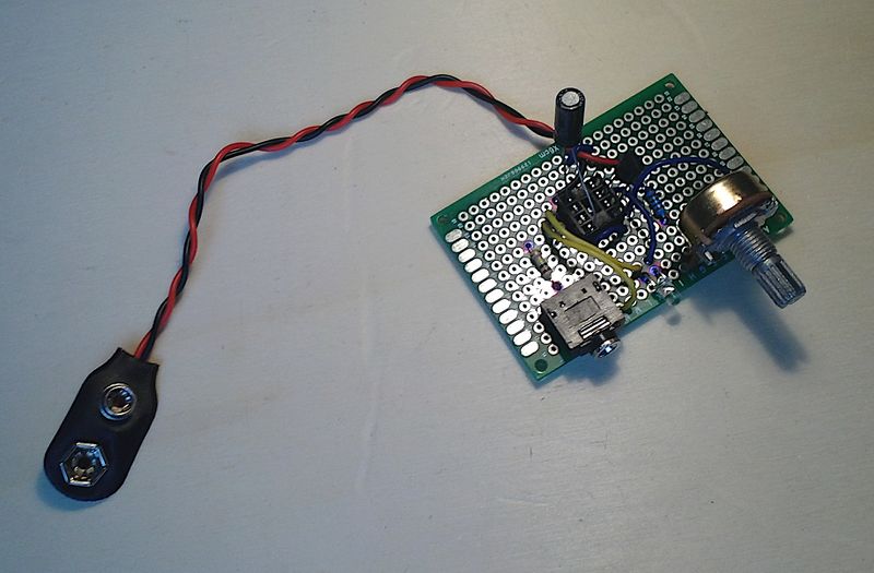
One of the simplest analog synths inspired by LOOK MUM NO COMPUTER https://www.youtube.com/channel/UCafxR2HWJRmMfSdyZXvZMTw
Difficulté
Facile
Durée
1 heure(s)
Catégories
Art, Électronique, Musique & Sons
Coût
10 EUR (€)
Sommaire
- 1 Introduction
- 2 Video d'introduction
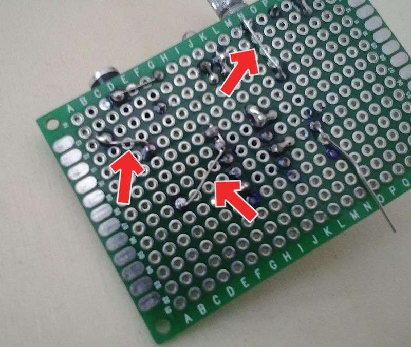
- 3 Étape 1 - Mark Prototype Board
- 4 Étape 2 - Solder Basic Components To Board
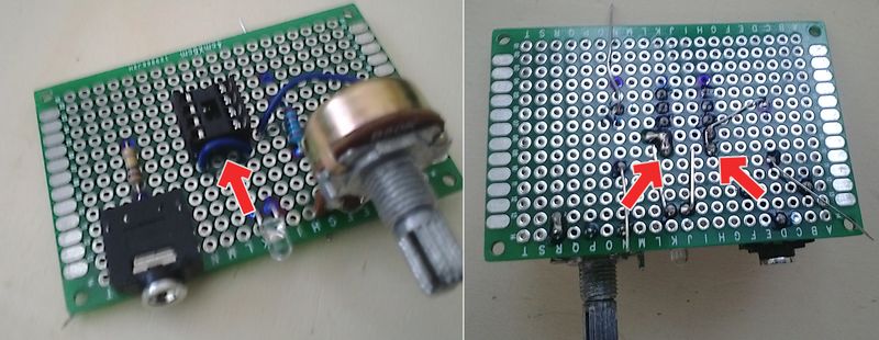
- 5 Étape 3 - Bridge Potentiometer Channels
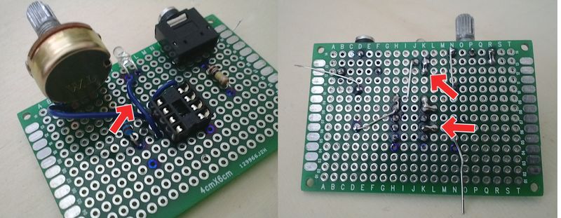
- 6 Étape 4 - Wire 1
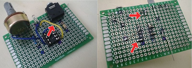
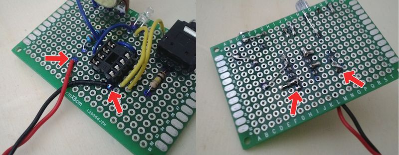
- 7 Étape 5 - Wire 2
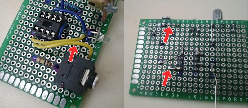
- 8 Étape 6 - Wire 3
- 9 Étape 7 - Wire 4
- 10 Étape 8 - Wire 5
- 11 Étape 9 - Solder component legs
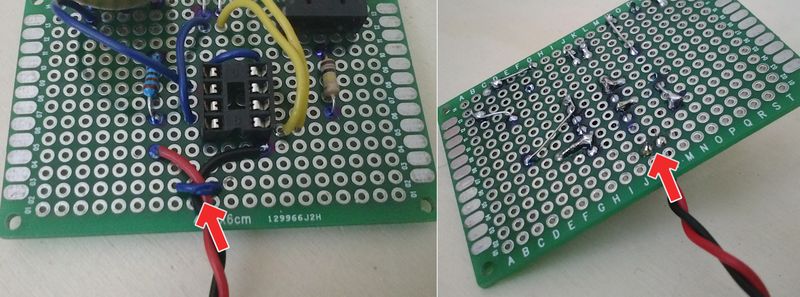
- 12 Étape 10 - Solder DC Connector
- 13 Étape 11 - Create Safety Strap
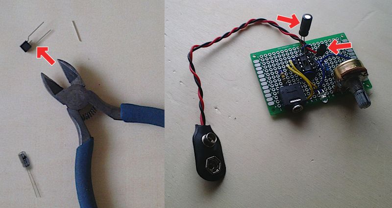
- 14 Étape 12 - Prepare moveable elements
- 15 Commentaires
Introduction
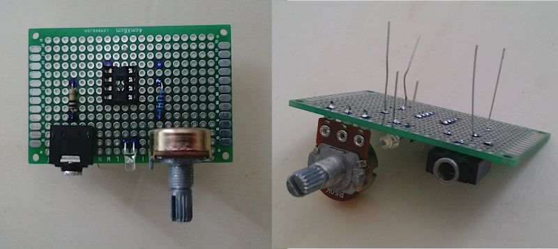
This simple diy analog synth is part of an upcoming series of little projects, that can be used to learn about basic electronics, while having fun with the result. As the synth has a chip socket, you will be able to change the pitch range of the sound through different capacitors. Just change it on the fly, or keep it and build several of these synths.
You can use sound effect software like http://rakarrack.sourceforge.net/. Check out the video!
There will be build-up tutorials in the future. Have fun!Youtube
Matériaux
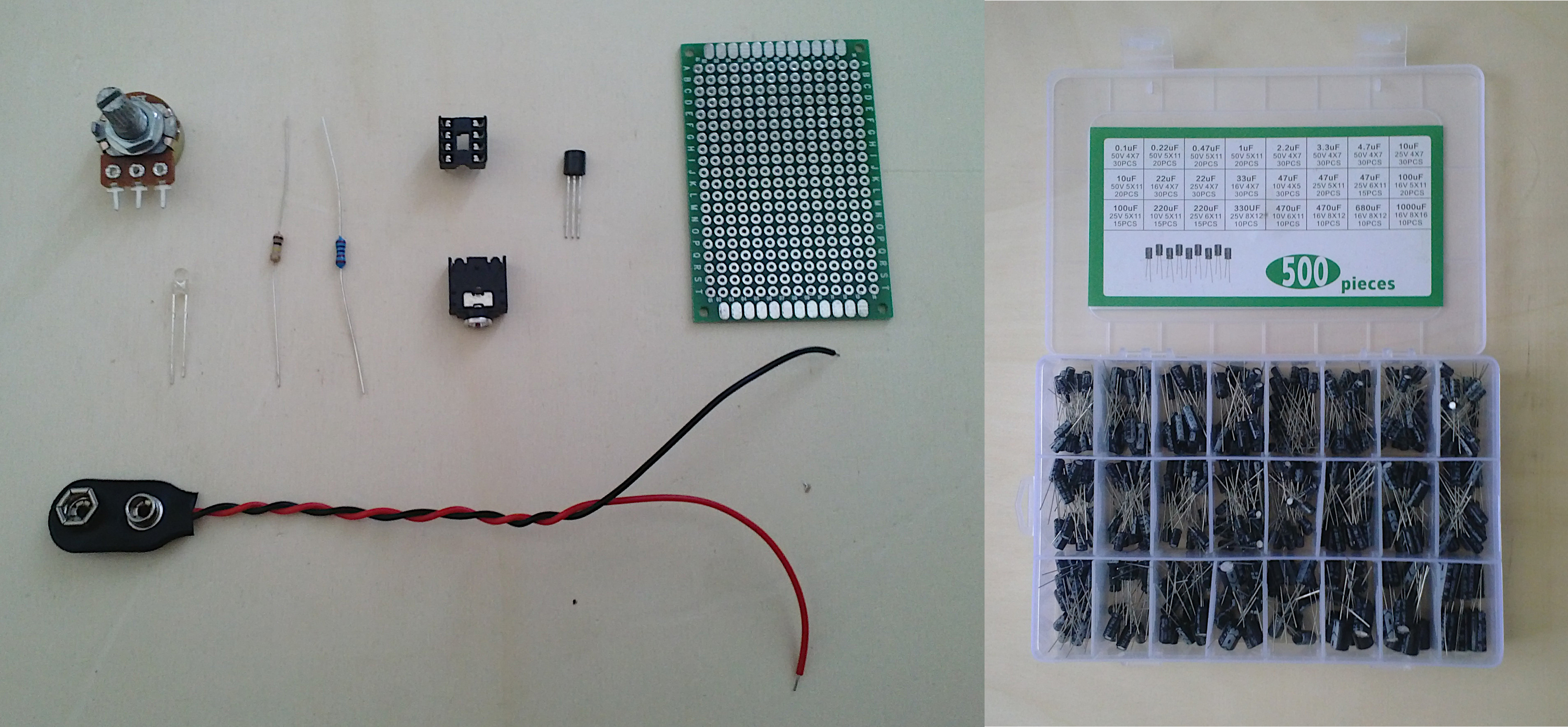
- 1k Resistor
- 100k Resistor
- Transistor SS9018HBU TO-92
- 10k Potentiometer
- LED Diode
- Capacitors (smaller value higher pitch)
- Wires (2 Colors)
- Prototype Board
- Battery Connector (and 9V Battery)
- Mini Jack Audio Socket
- 8 Pin RoHS PCB IC Socket
Outils
- Soldering iron
- Soldering wire
- Soldering grease
- Marker
- Sucker
- Pliers
Draft
 Français
 English
 Deutsch
 Español
 Italiano
 Português