Sommaire
- 1 Introduction
- 2 Étape 1 - Chose a front cover
- 3 Étape 2 - Get your image ready for printing
- 4 Étape 3 - Get the image ready for laser cutting
- 5 Étape 4 - Printing and Sticking to the PMMA sheet (3mm)
- 6 Étape 5 - Getting ready for laser cutting
- 7 Étape 6 - Front cover cutting
- 8 Étape 7 - Choose the right support size
- 9 Étape 8 - Laser cutting of the support
- 10 Étape 9 - Gluing the support magnets
- 11 Étape 10 - Flexible tabs
- 12 Étape 11 - Support assembly
- 13 Étape 12 - Adding the magnets to the front cover
- 14 Étape 13 - You're done !
- 15 Commentaires
Introduction
The vents of our homes serve as dust nests, get yellowish and have a very basic design. There are few models with a better design, but at excessive cost.
You'll be led through the steps required to create your own custom air vents, in harmony with your interior decoration, interchangeable, and easy to assemble and disassemble, which will allow you to clean them easily and carry them with you if you change housing.
You'll need access to a color printer and a laser cutting machine, available in most fablabs.
Étape 1 - Chose a front cover
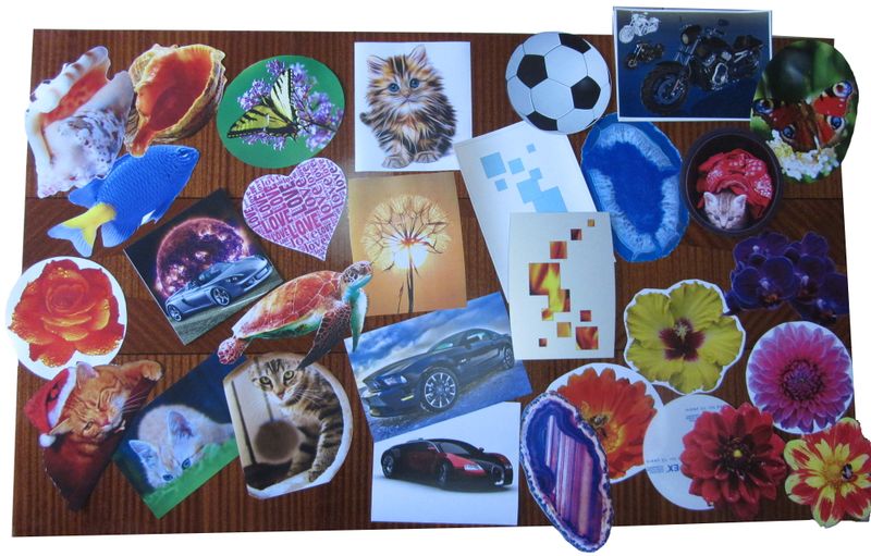
This step may be the most time consuming, especially if you spend hours on free pictures website going through thousands of thousands of nice pictures, unable to settle on one ...
We are only showcasing a few examples, your imagination is almost the only limit.
You can even create your very own photo montage or abstract artistic creation.
The chosen image (or images) must be of good quality (to be printed in A4 size) and must completely cover a circle of at least 15cm in diameter.
In some cases it will be necessary to choose a "simple" form to fulfill this condition.
Do not hesitate to tests and possibly create several front covers, they will be interchangeable and you will be able to vary your decoration according to your desires or your mood!
We made a set of examples do give you some inspiration : http://www.e-vent.fr/front/
Note : You can also paint directly on the front cover, in which case you can switch directly to the next step.
Étape 2 - Get your image ready for printing
Once your image is selected, make sure it will fit on the A4 sheet for printing, and that it will be big enough to hide the air hole behind.
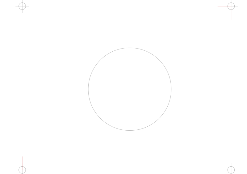
We made a template available for download : http://techdata.techno-innov.fr/E-Vent/Master.svg
You should of course adapt this template to the adhesive paper you'll be using for printing.
This template provides some help to get the proportions right but also for the front cover positioning for the laser cutting step.
We are using Inkscape (a free software) for this step, but other vector graphics software may do the job as well.
Insert your image in the file on the layer "Dessin", and resize it so that it fits between the crosses (cutting area), and covers at least the whole circle that we placed in the center. In some cases, you can cheat a bit by moving the center circle, its position does not really matter, as long as it is inside the cutting area.
Check that the definition of the image is sufficient, either by rendering on the screen, or by printing an essay on a draft. It's the appearance that matters, it's up to you to make sure that the image quality fits your expectations.
Étape 3 - Get the image ready for laser cutting
You must now define trace for laser cutting. To do this, use one of the vector drawing tools and draw an outline to your image. Adjust the color and thickness of the path to the constraints of the laser cutting machine you are about to use.
The trace may be as simple as a square or a circle, or follow exactly the shape of your drawing, or anything in between.
You should use the "Découpe" layer for this cutting shape, to be able to easily print your image without it being visible.
The trace must not get out of the cutting zone, which is also the printing zone and corresponds to the size of the self-adhesive sheet
In this example, the cutting shape is visible in red.
Étape 4 - Printing and Sticking to the PMMA sheet (3mm)
You can now print the drawing, but hide the cutting layer so that only the drawing and positioning marks are visible.
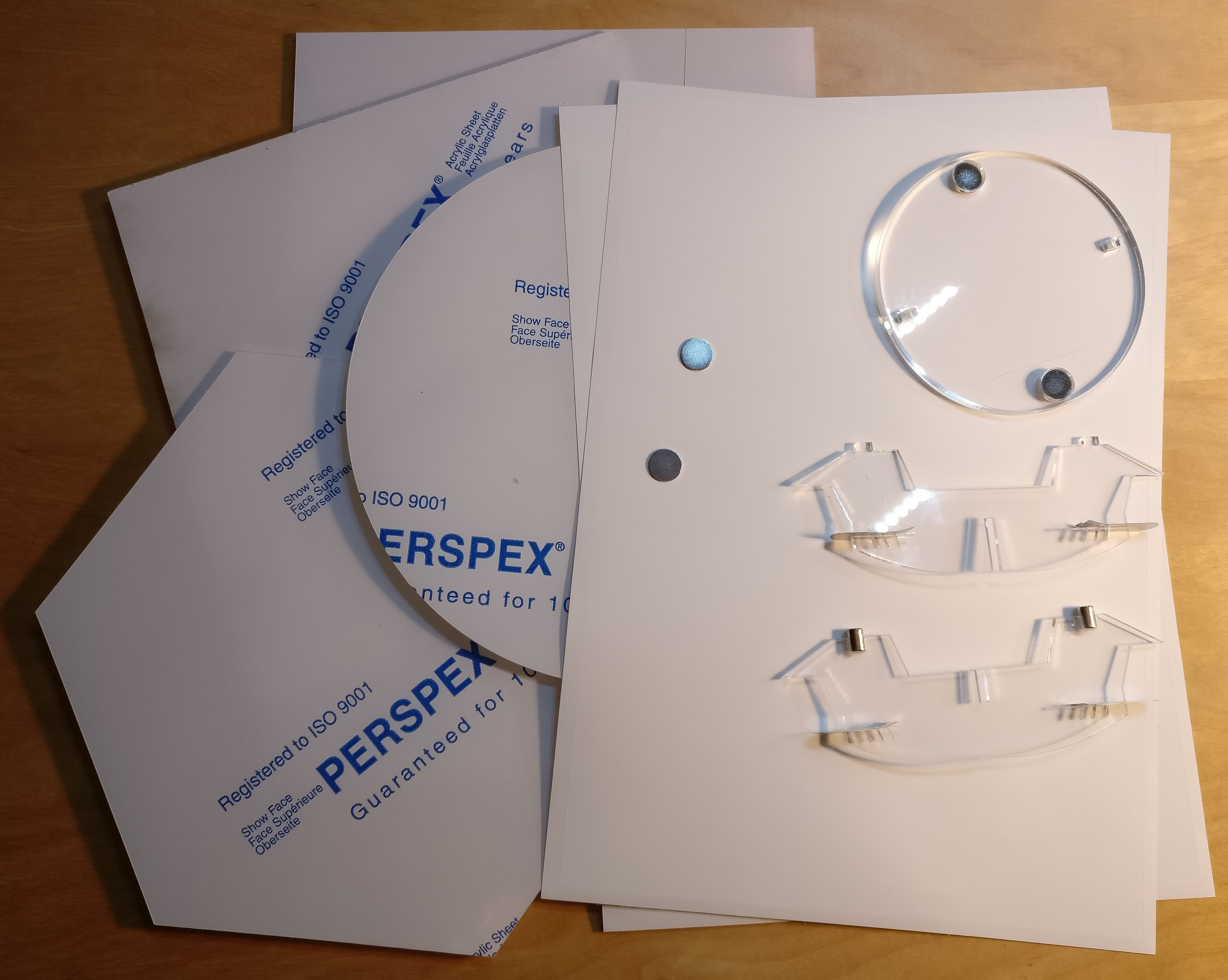
Once your front cover image is printed, you must stick it to the 3mm thick PMMA plate.
We've tested two solution which give good results.
- Method 1: with a piece of PVC pipe on which we flatten the drawing. Place the drawing with the printed face lying on the PVC, then take off the adhesive protection and roll the piece of tube on the PMMA, squeezing it hard, and being careful not to drag, but roll the tube. This method is effective if the positioning on the PMMA plate does not need to be precise, but very difficult to use if the positioning must be perfect.
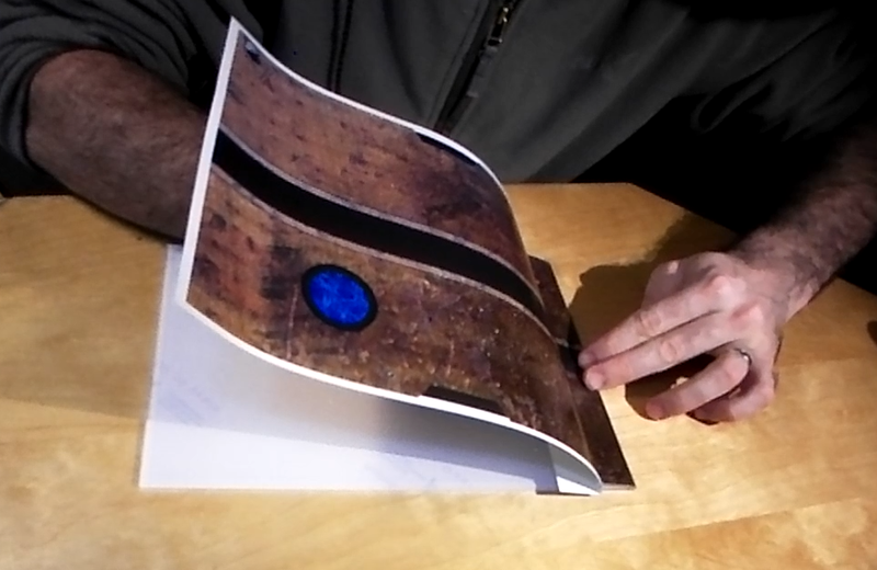
- Method 2: take off an angle of the drawing by folding the protective paper, then position the drawing on the PMMA without sticking the angle right away. Once the positioning is correct, stick the angle that has been cleared, then lift the unglued part and continue to remove the protection while gradually smoothing the drawing with a dry cloth so that it adheres without bubbles.
Étape 5 - Getting ready for laser cutting
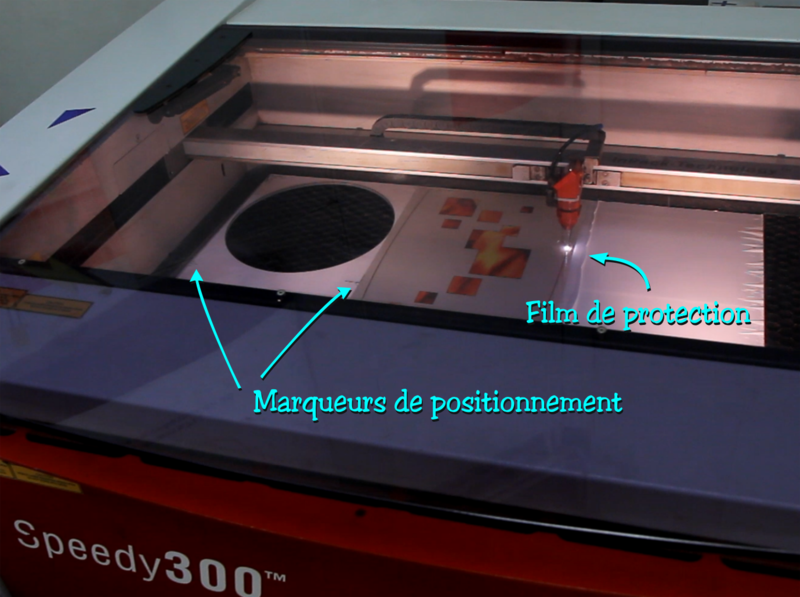
Once your front cover image is stuck to the PMMA, you must add some protective layer on top of it to prevent the flames (from the laser beam) from burning your print.
This is achieved with a piece of transfer film placed on top of the drawing. The film must be of sufficient size so that it covers the drawing without waste. This film will be marked by the flame, and once the film removed after cutting your front cover will be flawless.
Then, in order to cut the PMMA plate with the laser cutting machine following the layout defined above, keep only the "cutting" layer active, select the two angles of positioning and your cutting path, and export (or print to the laser cutting machine) the selection alone. This will simplify the positioning of the PMMA plate on the cutting bed of the laser cutting machine.
Étape 6 - Front cover cutting
Position your PMMA plate on the cutting machine, make the usual height adjustments of the tray, and position the laser in the center of one of the positioning marks.
Then move your laser in only one direction to get closer to another marker, and reposition the PMMA plate so that the laser pointer is on the marker line.
Do this by alternating the laser movements always on the same line, until the laser pointer passes through the centers of the markers when moving on a line, without having to move the PMMA plate.
Move the laser pointer to the center of the first marker, without moving the PMMA plate.
Position the cutting path on the laser cutting software so that the corner of the path corresponds to the position of the laser, and the cutting area is over your drawing on the PMMA plate.
You can do a first test on a draft paper on which you have done a test print.
Once you are sure of your positioning you can launch the cutting process !
You now have the front cover of your air vent, let's move to the support.
Étape 7 - Choose the right support size
The laser cutting of the support pieces is quite straightforward.
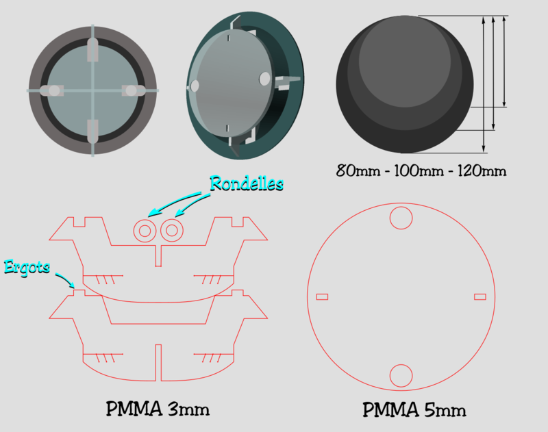
There's actually three sizes available for the support, matching the usual air vent sizes : 80mm, 100mm and 120mm.
Measure the diameter of the air duct for which you want to replace the air vent and choose the nearest size.
If the size does not exactly match it does not matter, the tab system allows to adapt to differences in sizes.
CAD files for laser cutting available in the "Files" section and on our server : http://techdata.techno-innov.fr/E-Vent/
You must use the "Cross" file adapted to the size of the air duct for cutting in 3mm thick PMMA, and the common file "Vent / Support_v05_5mm.svg Support_v05_5mm.svg" to cut the 5mm thick disc common to all sizes in a 5mm thick PMMA plate.
For the size selection, the file "Support_Croix_v05_D80.svg" is suitable for a vent of diameter ranging from 68 to 88mm, the file "Support_Croix_v05_D100.svg" is suitable for a vent of diameter from 88mm to 108mm, and the file "[http: //techdata.techno-innov.fr/E-Vent/Support_Croix_v05_D120.svg Support_Croix_v05_D120.svg]" is suitable from 108mm to 128mm.
Étape 8 - Laser cutting of the support
Nothing special for this step : once you have selected the two appropriate cutting files, make the cuts in PMMA of 3mm and 5mm. You can use left-overs as these are relatively small pieces.
Do not lose the two washers from the 3mm PMMA, they are required for assembly!
Étape 9 - Gluing the support magnets
This is the most tricky step of the support assembly
Be careful, the use of cyanoacrylate glue requires attention. Respect the indications found on the packaging.
First, glue the two 3mm thick washers in the two holes in the 5mm PMMA disc. These two washers must be flush with one of the faces, and as straight as possible. The easiest way to obtain a good result is to put the disc on a rough sheet, to put one or two drops of glue on the round of the washers, and to place them in the holes (one per hole) by pressing well with the tip of a pen so that the washer goes well to the bottom. Do not use your finger to push, cyanoacrylate glue has the annoying tendency to stick better on the fingers than anywhere else!
Let it dry for a minute at least, and then glue the first magnets (the 12mm wide discs) by placing a small drop of glue (cyanoacrylate) inside the holes of the PMMA disc, on top of the washers, then depositing the magnets in the holes (one in each hole). Make sure to use a very small drop of glue so as not to clog the washers hole, which will receive the 6mm cylinder magnets.
Beware, neodymium magnets are very powerful but also quite fragile, and can break if they receive a shock (for example by sticking together). It is also difficult to separate them, so if your magnets are stuck together, start by separating them before applying the glue points.
Also try to stick them in the same direction, so that your facades can be interchangeable.
Then stick the cylindrical magnets on the half of the cross with two notches to accommodate the magnets. To perform this step correctly, turn the disc you have assembled, and put the two magnets in the holes formed by the washers. This keeps them in place and prevents making mistake in the magnets orientation. Position the other part of the cross on the cylinder by inserting the pins in the two rectangular holes provided for this purpose. And now, put a drop of glue in each of the two notches to accommodate the magnets on the first half of the cross and nest it in the other half, until it is in contact with the disc and the cylindrical magnets.
Let the glue take for a minute, and when you remove the cross the magnets should follow.
Étape 10 - Flexible tabs
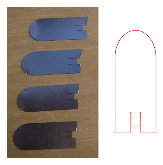
The last part of the support is a set of four identical flexible metallic tabs.
These tabs can be cut in a thin and flexible steel plate (150microns), which bends without scoring. You can perform the cutting either with scissors or laser.
Laser cutting machines that allow this type of cutting are not common in FabLabs (I have never seen one) and cutting in a suitable sheet of metal is not easy.
We did the first tests by scissoring in old CMS stencils used for the assembly of electronic boards, then we finally made a series of tabs using laser cutting.
The tabs are cut according to this drawing : http://techdata.techno-innov.fr/E-Vent/Lamelles_v01.svg
You can make them yourself (be careful, the metal is very sharp at this thickness) or buy them on our shop.
Étape 11 - Support assembly
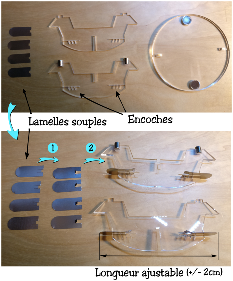
Positionning the tabs on the support is done in two small steps.
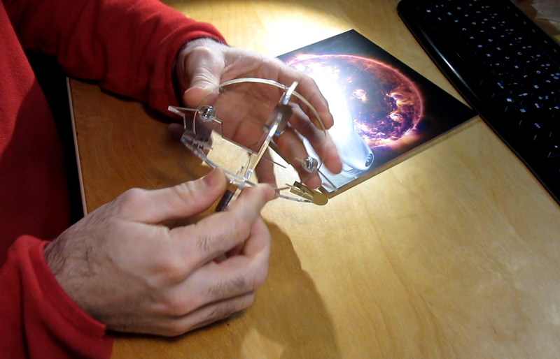
Start by raising the small lug of each tab, then insert the tabs one by one in the slots, positioning the lug in one of the adjustment notches.
Check that the tabs positionning is right by inserting the support into the vent pipe. the support must hold firmly, the tabs being slightly bent, without forming a marked fold. If the position is adequate, raise the side lugs of the tabs away from the center lug to hold the tabs in position.
Otherwise, change the position of the tabs to the appropriate notches.
The assembly of the support is done. It is not necessary to glue the two elements of the cross, the magnets will hold everything in place, and thus the support remains removable and easy to clean.
Étape 12 - Adding the magnets to the front cover
The last step consists in gluing the magnets to the back of the front cover.
To avoid making any mistake in the magnets orientation, the easiest way is to put the support disc on a table, the magnets facing up, then put a sheet of paper on top of it, and position the last two magnets above the magnets of the support disk. Thus the direction of the magnets and the spacing will necessarily be the right ones.
Put a drop of glue (cyanoacrylate) on each magnet, then position the front cover over the support so that it is as centered as possible (unless your air vent is for a corner, or is too close to a wall edge, in this case make the positioning according to your needs) and press firmly for a minute.
When you raise the front cover, the magnets must come with it (and the support disk should follow)
Étape 13 - You're done !
Your air vent decoration is now complete, you can assemble the support and put it in the ventilation duct, and place the front cover on!
Si vous êtes intéressé par une version lumineuse, vous pouvez fixer une carte avec un micro-contrôleur et un bandeau de leds dans le support.
Nous avons commencé à faire quelques tests, et le rendu est assez sympathique.
Published


 Français
 English
 Deutsch
 Español
 Italiano
 Português