Sommaire
- 1 Introduction
- 2 Étape 1 - Chose a front cover
- 3 Étape 2 - Get your image ready for printing
- 4 Étape 3 - Get the image ready for laser cutting
- 5 Étape 4 - Printing and Sticking to the PMMA sheet (3mm)
- 6 Étape 5 - Getting ready for laser cutting
- 7 Étape 6 - Front cover cutting
- 8 Étape 7 - Choose the right support size
- 9 Étape 8 - Laser cutting of the support
- 10 Étape 9 - Gluing the support magnets
- 11 Étape 10 - Lamelles souples
- 12 Étape 11 - Assemblage du support
- 13 Étape 12 - Ajout des aimants sur la façade
- 14 Étape 13 - C'est fini, prêt à être mis en place !
- 15 Étape 14 - Pour aller plus loin
- 16 Commentaires
Introduction
The vents of our homes serve as dust nests, get yellowish and have a very basic design. There are few models with a better design, but at excessive cost.
You'll be led through the steps required to create your own custom air vents, in harmony with your interior decoration, interchangeable, and easy to assemble and disassemble, which will allow you to clean them easily and carry them with you if you change housing.
You'll need access to a color printer and a laser cutting machine (available in most fablabs)
Matériaux
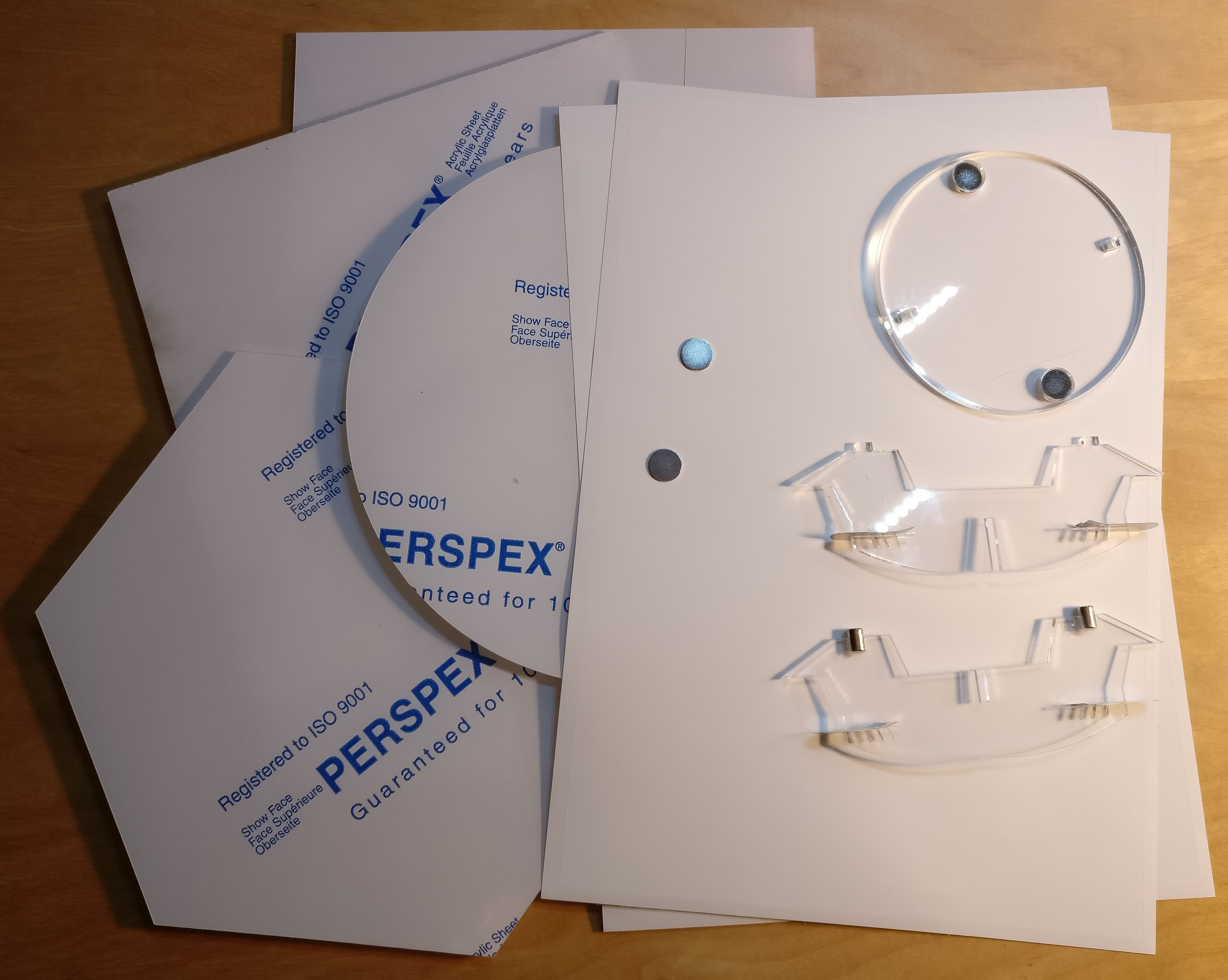
One 3mm thick PMMA sheet (about 21cm x 40cm or 30cm x 30cm) and one 5mm thick PMMA sheet (10cm x 10cm, scraps can often be enough)
6 neodimium magnets (two discs of 1mm x 12mm, two discs of 1mm x 10mm and two cylinders of 6mm x 8mm)
Printable self-adhesive polyester foil in A4 size
Flexible metal tabs
Cyanoacrylate glue
Transparent transfer film
Outils
Laser printer (not tested with inkjet printer, but may be OK if using inkjet polyester stamp foils)
Laser cutting machine
Roller (glass bottle, PVC tube, rolling pin, ...)
Inkscape vector graphics software (or any replacement you like)
Étape 1 - Chose a front cover
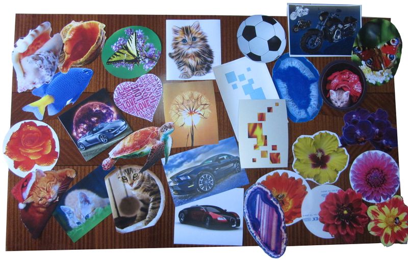
This step may be the most time consuming, especially if you spend hours on free pictures website going through thousands of thousands of nice pictures, unable to settle on one ...
We are only showcasing a few examples, your imagination is almost the only limit.
You can even create your very own photo montage or abstract artistic creation.
The chosen image (or images) must be of good quality (to be printed in A4 size) and must completely cover a circle of at least 15cm in diameter.
In some cases it will be necessary to choose a "simple" form to fulfill this condition.
Do not hesitate to tests and possibly create several front covers, they will be interchangeable and you will be able to vary your decoration according to your desires or your mood!
We made a set of examples do give you some inspiration : http://www.e-vent.fr/front/
Note : You can also paint directly on the front cover, in which case you can switch directly to the next step.
Étape 2 - Get your image ready for printing
Once your image is selected, make sure it will fit on the A4 sheet for printing, and that it will be big enough to hide the air hole behind.
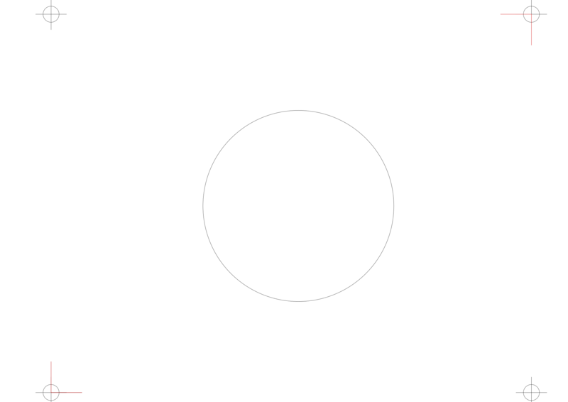
We made a template available for download : http://techdata.techno-innov.fr/E-Vent/Master.svg
You should of course adapt this template to the adhesive paper you'll be using for printing.
This template provides some help to get the proportions right but also for the front cover positioning for the laser cutting step.
We are using Inkscape (a free software) for this step, but other vector graphics software may do the job as well.
Insert your image in the file on the layer "Dessin", and resize it so that it fits between the crosses (cutting area), and covers at least the whole circle that we placed in the center. In some cases, you can cheat a bit by moving the center circle, its position does not really matter, as long as it is inside the cutting area.
Check that the definition of the image is sufficient, either by rendering on the screen, or by printing an essay on a draft. It's the appearance that matters, it's up to you to make sure that the image quality fits your expectations.
Étape 3 - Get the image ready for laser cutting
You must now define trace for laser cutting. To do this, use one of the vector drawing tools and draw an outline to your image. Adjust the color and thickness of the path to the constraints of the laser cutting machine you are about to use.
The trace may be as simple as a square or a circle, or follow exactly the shape of your drawing, or anything in between.
You should use the "Découpe" layer for this cutting shape, to be able to easily print your image without it being visible.
The trace must not get out of the cutting zone, which is also the printing zone and corresponds to the size of the self-adhesive sheet
In this example, the cutting shape is visible in red.
Étape 4 - Printing and Sticking to the PMMA sheet (3mm)
You can now print the drawing, but hide the cutting layer so that only the drawing and positioning marks are visible.
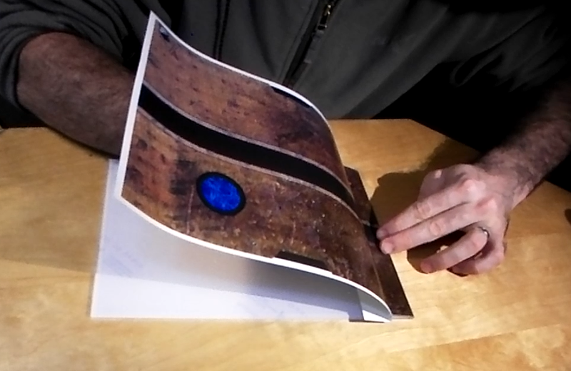
Once your front cover image is printed, you must stick it to the 3mm thick PMMA plate.
We've tested two solution which give good results.
- Method 1: with a piece of PVC pipe on which we flatten the drawing. Place the drawing with the printed face lying on the PVC, then take off the adhesive protection and roll the piece of tube on the PMMA, squeezing it hard, and being careful not to drag, but roll the tube. This method is effective if the positioning on the PMMA plate does not need to be precise, but very difficult to use if the positioning must be perfect.
- Method 2: take off an angle of the drawing by folding the protective paper, then position the drawing on the PMMA without sticking the angle right away. Once the positioning is correct, stick the angle that has been cleared, then lift the unglued part and continue to remove the protection while gradually smoothing the drawing with a dry cloth so that it adheres without bubbles.
Étape 5 - Getting ready for laser cutting
Once your front cover image is stuck to the PMMA, you must add some protective layer on top of it to prevent the flames (from the laser beam) from burning your print.
This is achieved with a piece of transfer film placed on top of the drawing. The film must be of sufficient size so that it covers the drawing without waste. This film will be marked by the flame, and once the film removed after cutting your front cover will be flawless.
Then, in order to cut the PMMA plate with the laser cutting machine following the layout defined above, keep only the "cutting" layer active, select the two angles of positioning and your cutting path, and export (or print to the laser cutting machine) the selection alone. This will simplify the positioning of the PMMA plate on the cutting bed of the laser cutting machine.
Étape 6 - Front cover cutting
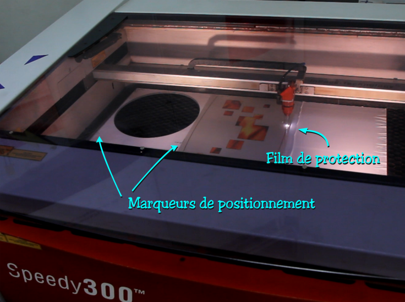
Position your PMMA plate on the cutting machine, make the usual height adjustments of the tray, and position the laser in the center of one of the positioning marks.
Then move your laser in only one direction to get closer to another marker, and reposition the PMMA plate so that the laser pointer is on the marker line.
Do this by alternating the laser movements always on the same line, until the laser pointer passes through the centers of the markers when moving on a line, without having to move the PMMA plate.
Move the laser pointer to the center of the first marker, without moving the PMMA plate.
Position the cutting path on the laser cutting software so that the corner of the path corresponds to the position of the laser, and the cutting area is over your drawing on the PMMA plate.
You can do a first test on a draft paper on which you have done a test print.
Once you are sure of your positioning you can launch the cutting process !
You now have the front cover of your air vent, let's move to the support.
Étape 7 - Choose the right support size
The laser cutting of the support pieces is quite straightforward.
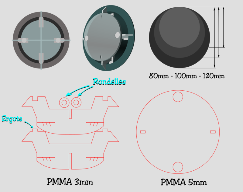
There's actually three sizes available for the support, matching the usual air vent sizes : 80mm, 100mm and 120mm.
Measure the diameter of the air duct for which you want to replace the air vent and choose the nearest size.
If the size does not exactly match it does not matter, the tab system allows to adapt to differences in sizes.
CAD files for laser cutting available in the "Files" section and on our server : http://techdata.techno-innov.fr/E-Vent/
You must use the "Cross" file adapted to the size of the air duct for cutting in 3mm thick PMMA, and the common file "Vent / Support_v05_5mm.svg Support_v05_5mm.svg" to cut the 5mm thick disc common to all sizes in a 5mm thick PMMA plate.
For the size selection, the file "Support_Croix_v05_D80.svg" is suitable for a vent of diameter ranging from 68 to 88mm, the file "Support_Croix_v05_D100.svg" is suitable for a vent of diameter from 88mm to 108mm, and the file "[http: //techdata.techno-innov.fr/E-Vent/Support_Croix_v05_D120.svg Support_Croix_v05_D120.svg]" is suitable from 108mm to 128mm.
Étape 8 - Laser cutting of the support
Nothing special for this step : once you have selected the two appropriate cutting files, make the cuts in PMMA of 3mm and 5mm. You can use left-overs as these are relatively small pieces.
Do not lose the two rings from the 3mm PMMA, they are required for assembly!
Étape 9 - Gluing the support magnets
This is the most tricky step of the support assembly
Be careful, the use of cyanoacrylate glue requires attention. Respect the indications found on the packaging.
First, glue the two 3mm thick washers in the two holes in the 5mm PMMA disc. These two washers must be flush with one of the faces, and as straight as possible. The easiest way to obtain a good result is to put the disc on a rough sheet, to put one or two drops of glue on the round of the washers, and to place them in the holes (one per hole) by pressing well with the tip of a pen so that the washer goes well to the bottom. Do not use your finger to push, cyanoacrylate glue has the annoying tendency to stick better on the fingers than anywhere else!
Laissez sécher une bonne minute, puis procédez au collage de premiers aimants (les disques de 12mm de diamètre) en déposant une petite goutte de colle (toujours la cyanoacrylate) à l'intérieur des trous du disque en PMMA, sur le dessus des rondelles, puis en déposant les aimants dans les trous (toujours un dans chaque trou).
Attention, les aimants néodyme sont très puissants mais aussi assez fragiles, et peuvent casser si ils reçoivent un choc (par exemple en se collant entre eux). Il est aussi difficile de les séparer, donc si vos aimants sont collés ensemble, commencez par les séparer avant de poser les points de colle.
Veillez aussi si possible à les coller dans le même sens, pour que vos façades soient interchangeables.
Ensuite collez les aimants cylindriques sur la moitié de croix disposant de deux encoches pour accueillir les aimants. Pour réaliser cette étape correctement, retournez le disque que vous venez d'assembler, et mettez les deux aimants dans les trous formés par les rondelles. Cela permet de les maintenir en place et de ne pas se tromper de sens. Positionnez l'autre partie de la croix sur le cylindre en faisant rentrer les ergots dans les deux trous rectangulaires prévus à cet effet. Et maintenant, mettez une goutte de colle dans chacune des deux encoches destinées à accueillir les aimants sur la première moitié de la croix et imbriquez-là dans l'autre moitié, jusqu'à ce quelle soit en contact avec le disque et les aimants cylindriques.
Laissez prendre la colle une bonne minute, et lorsque vous retirez la croix les aimants doivent venir en même temps.
Étape 10 - Lamelles souples
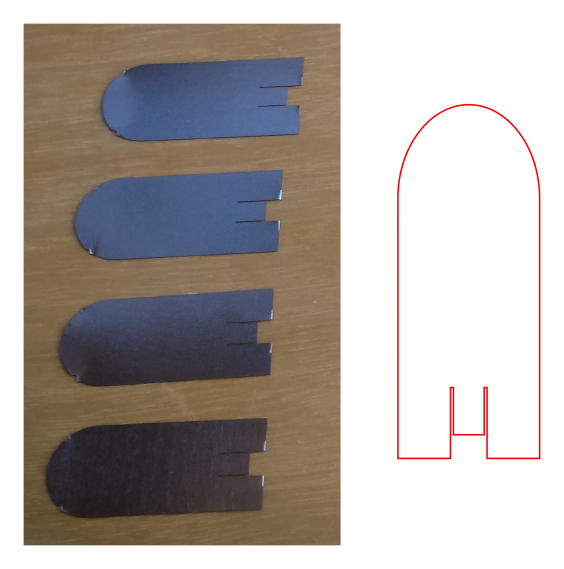
Le dernier élément du support est un ensemble de quatres lamelles métaliques souples.
Ces lamelles peuvent être découpées dans une plaque d'acier fin (150microns) et souple, qui plie sans marquer, soit avec des ciseaux, soit au laser.
Les machines de découpe laser permettant ce type de découpe ne sont pas courantes dans les FabLab (je n'en ai jamais vu) et la découpe dans une feuille de métal adaptée n'est pas aisée.
Nous avons fait les premiers tests en découpant aux ciseaux dans de vieux pochoirs CMS utilisés pour l'assemblage de cartes électroniques, puis nous avons finalement fait faire une série de lamelles en découpe laser.
Les lamelles sont faites selon ce modèle : http://techdata.techno-innov.fr/E-Vent/Lamelles_v01.svg
Vous pouvez les fabriquer vous-même (attention, le métal est très coupant à cette épaisseur) ou les acheter sur notre boutique.
Étape 11 - Assemblage du support
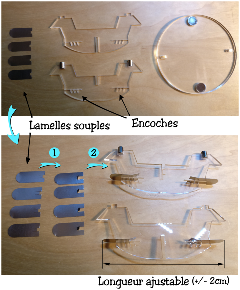
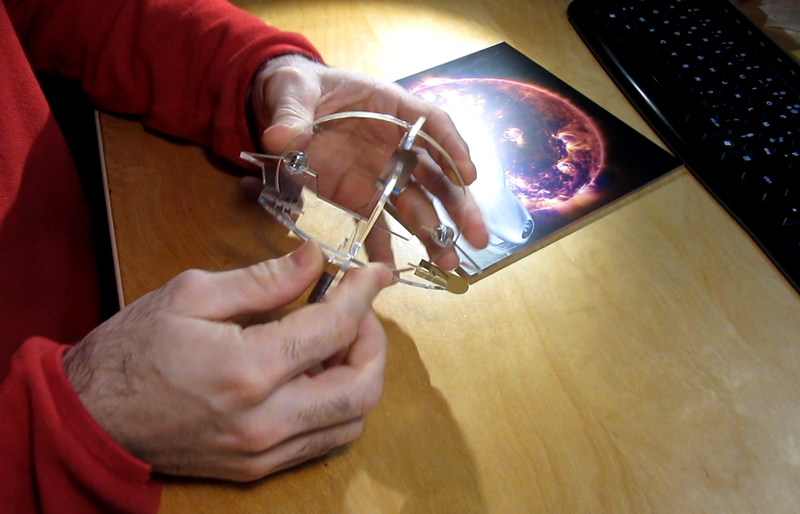
L'assemblage des lamelles souples sur le support se fait en deux étapes.
Commencez par relever le petit ergot de chaque lamelle, puis insérez les lamelles une à une dans les fentes, en positionnant l'ergot dans une des encoches de réglage.
Testez l'écartement en insérant le support dans le conduit de ventilation. le support doit tenir fermement, les languettes étant légèrement pliées, sans former de pli marqué. Si l'écartement convient, relevez les les ergots latéraux des lamelles souples à l'opposé de l'ergot central de façon à maintenir les lamelles en position.
Sinon, re-positionnez les lamelles dans les encoches plus appropriées.
L'assemblage du support est terminé. Il n'est pas nécessaire de coller les deux éléments de la croix, les aimants maintiendront le tout en place, et le support reste ainsi démontable et simple à nettoyer.
Étape 12 - Ajout des aimants sur la façade
La dernière étape consiste à coller les aimants à l'arrière de la façade.
Pour ne pas se tromper de sens, le plus simple est de poser le disque de support sur une table, les aimants sur le dessus, puis de poser une feuille de papier par dessus, et de positionner les deux derniers aimants au dessus des aimants du disque de support. Ainsi le sens des aimants et l'écartement seront forcément corrects.
Mettez une goutte de colle sur chaque aimant, puis positionnez la façade au dessus du support de façon à ce qu'elle soit le plus centrée possible (sauf si votre bouche d'aération est destinée à un coin, ou bien se trouve trop proche d'un bord de mur, dans ce cas là faites le positionnement en fonction de vos besoins) et pressez fermement pendant une minute.
Lorsque vous retirez la façade les aimants doivent rester dessus.
Étape 13 - C'est fini, prêt à être mis en place !
Voilà, votre bouche de ventilation décorative est désormais terminée, vous pouvez assembler le support et le mettre dans le conduit de ventilation, et aimanter la façade dessus :)
Étape 14 - Pour aller plus loin
Si vous êtes intéressé par une version lumineuse, vous pouvez fixer une carte avec un micro-contrôleur et un bandeau de leds dans le support.
Nous avons commencé à faire quelques tests, et le rendu est assez sympathique.
Yes


 Français
 English
 Deutsch
 Español
 Italiano
 Português