Sommaire
- 1 Étape 1 - Setting the hangers on the squared tube
- 2 Étape 2 - Setting up the lateral fixation metallic flat of the secondary reflector
- 3 Étape 3 - Fixation of the secondary reflector
- 4 Étape 4 - Setting up the absorber tube in the cavity (adjustment of its lateral position and its height)
- 5 Étape 5 - Setting up the absorber tube in the cavity (adjustment of its lateral position and its height)
- 6 Étape 6 - Setting up the reflective covers on the edges of the receiver
- 7 Étape 7 -
- 8 Étape 8 - Setting up the L and the junctions
- 9 Étape 9 - Putting the thermal insulation around the cavity
- 10 Étape 10 - Setting up the water tube
- 11 Étape 11 - Sealing with the cover
- 12 Étape 12 - Setting up the glass (with a junction under and above)
- 13 Étape 13 - Placing the receiver
- 14 Étape 14 - Points to improve
- 15 Commentaires
Matériaux
Outils
Étape 1 - Setting the hangers on the squared tube
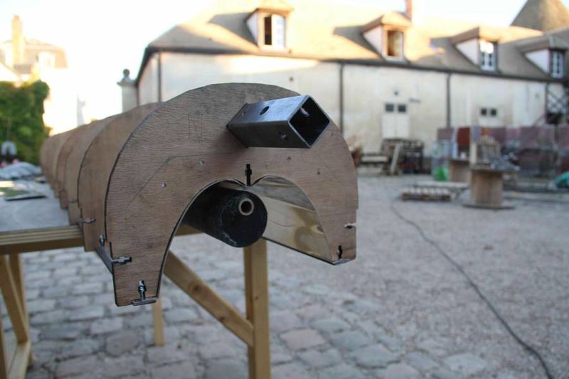
Cut the squared tube at a length of 2.2 m.
Put the 10 hangers on the squared tube, with a spacing of 22 cm.
Étape 2 - Setting up the lateral fixation metallic flat of the secondary reflector
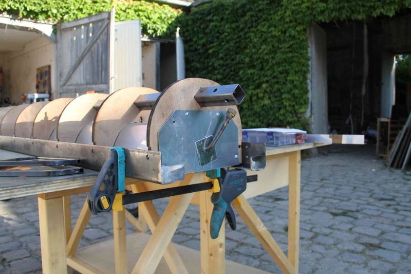
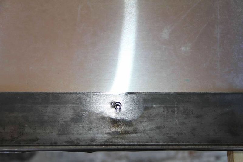
Cut the flat at a length of 2 m. Drill it according to the plan: 10 holes with a diameter of 4 mm, 10 mm from the edges, 220 mm the distance between them. Mill the entry of the hole with a drill having a diameter of 8 mm. It is important that the screw with the flat head covers the surface of the flat, without surpassing it. This is the position that creates the right rigidity to the receiver, by posing a precise distance between the hangers. Attention to drill in the same manner the two flats, so that the hangers are perpendicular to the receiver axis: drill both together with a pillar drill.
Étape 3 - Fixation of the secondary reflector
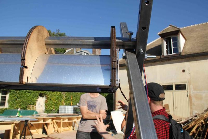
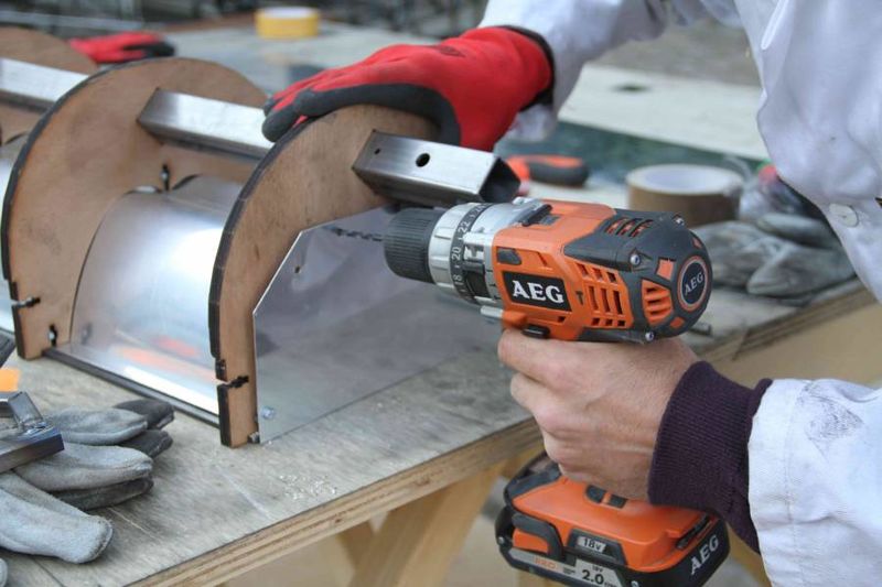
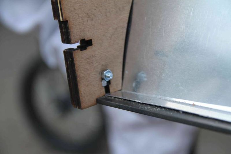
Put the 3 preformed portions of the reflector in their set up, with an overlap similar to the roof tiles “top-below”. Begin by fixing entirely one edge: put the lateral flat on the side of the preformed reflector. Put the screw in each hole, in order to fix the square tube. Pinch the nut to screw without damaging the hanger.
Étape 4 - Setting up the absorber tube in the cavity (adjustment of its lateral position and its height)
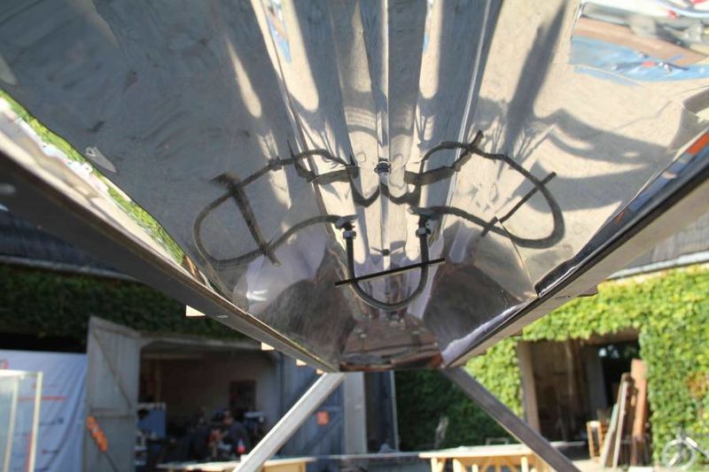
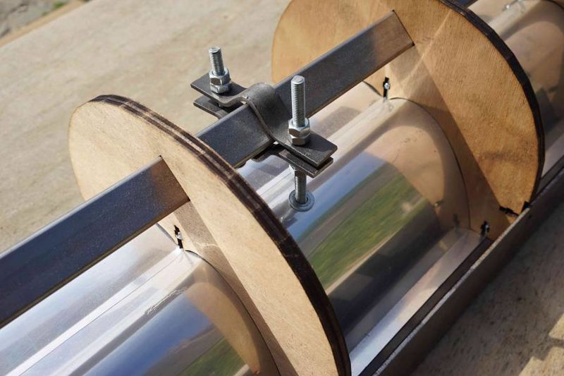
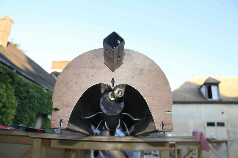
Prepare the two supports as described below: Between two tubes with a diameter of 55 mm clamped in a nut, curve in the center a U threaded rod having a length of 320 mm and a diameter of 6 mm. File the interior of the U rod in order to smooth the contact surface with the absorber tube. Prepare a metallic flat with the dimensions of 20x90 mm, drill two centered holes with a diameter of 8 mm at a 68 mm distance one from another. Prepare the two flats with the dimensions 120x20, put them in the nut in order to fix them in the main beam: 1 central folding at 90° and at a distance of 30 mm, two folds at 45°. Drill the two plats at a distance of 68 mm, with a diameter of 8 mm. Drill the secondary reflector at 520 mm from each extremity, symmetrical to the central axis. Insert the U threaded rod in the holes.
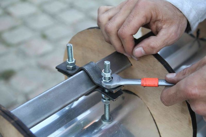
Put the flat on the threaded rod, afterwards the nut in each branches of the threaded rod. Put the U threaded rod in the holes of the secondary reflector; insert two nuts, put the two flats in order to pinch the main beam of the receiver. Complete with two nuts.
Étape 5 - Setting up the absorber tube in the cavity (adjustment of its lateral position and its height)
Put the absorber tube as follows:
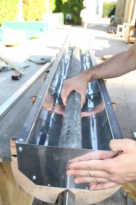
Put the receiver on the table, on the opposite side: the secondary reflector upwards. Slip the tube between the two U. You can turn over the receiver, to suspend the tube and to access easily the top screws. Adjust the position of the tube, in order to be centered, horizontal and as close as possible to the secondary reflector, without touching it (even the screws, to avoid the thermal bridge).
Étape 6 - Setting up the reflective covers on the edges of the receiver
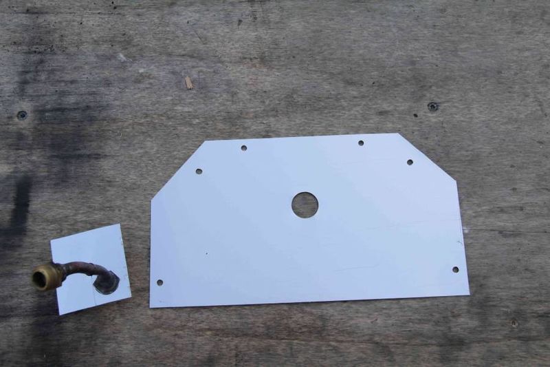
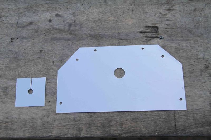
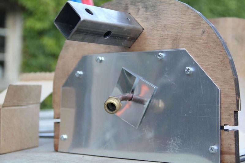
Cut a mirror sheet as indicated in the figure (230x125 mm, angles from the side smaller than 40mm).
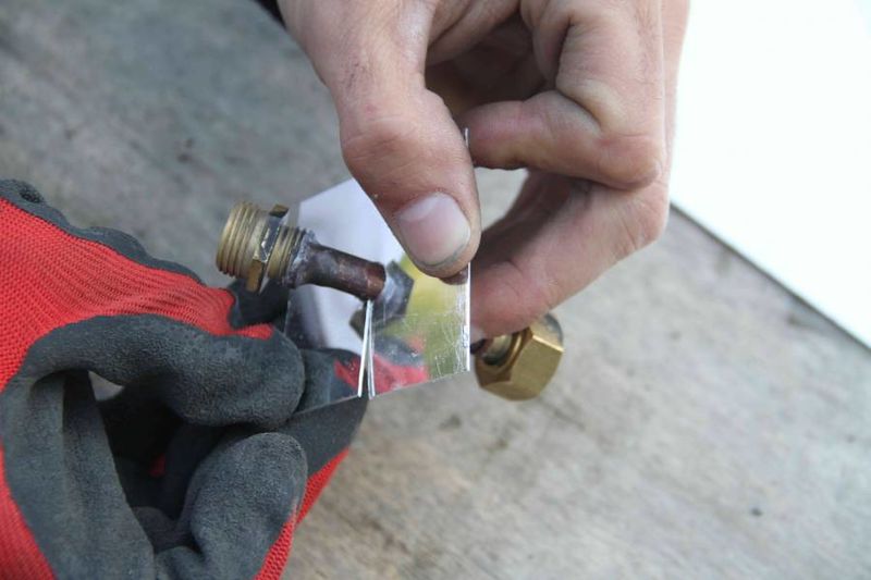
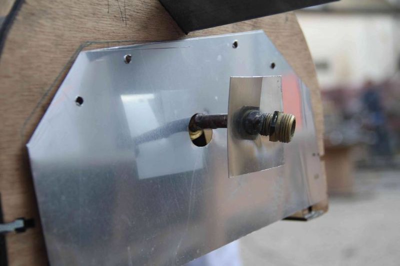
Drill holes having a diameter of 4 mm: on the inferior part 18 mm from the lower edge, 8 mm from the lateral edge, on the superior part 40 mm from the central part, and 10 mm from the upper edge. Drill a centered hole having a 20 mm diameter, corresponding to the height of the absorber tube’s exit: the nozzle height is different at each extremity (between the water entry and the vapor exit). We suggest to measure the precise position from the real position of the absorber tube.
Étape 7 -
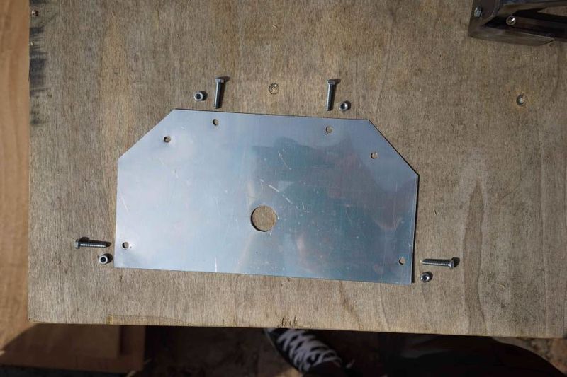
The interior screws are inserted up the pre-drilled hole of the hanger, where the support screw of the secondary reflector is inserted. For the upper screw, drill a hole in front of the holes of the mirror sheet.
We can seal the junction of the secondary reflector with the final cover, by applying a temperature resistant filler (at least 300°C).
Étape 8 - Setting up the L and the junctions
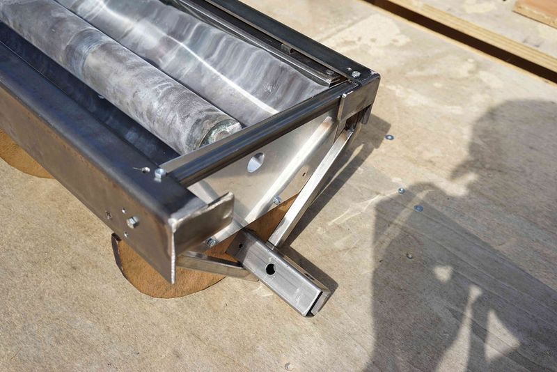
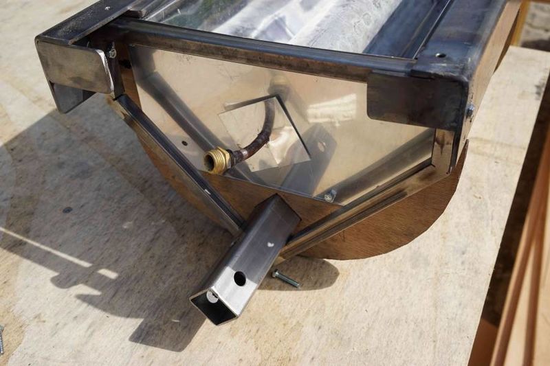
Put the Ls on both sides of the receiver. Fix the junctions on the main beam with two screws 20 mm long and a diameter of 5 mm. Screw the junctions in the lateral and inferior parts of the Ls. If the junctions are too little in the Ls, adjust by using the spacers. Verify that the distance between the Ls and the downside of the secondary reflector is constantly greater than 5 mm: this distance is necessary to assure that the glass of 4 mm thick will not break.
Étape 9 - Putting the thermal insulation around the cavity
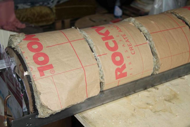
Take a plaque of stone wool (alternative material: wood wool, cellulose wadding; the cotton is not appropriated because of the high temperatures), thick of 10 cm. Cut a strip large of 570 mm and 9 times a length of 210 mm. Make thinner the strip on its edges and on the central part, as mentioned in the schema (thickness of 3 cm on the edge, inclined cut on 12 cm width + 5 cm cut width and depth on both sides of the center). Make the strip thinner where the support of the absorber tube should come.
Use a mask and a pair of gloves to avoid breathing the carcinogenic fibers. Try to handle the material as gentle as possible, in order to limit the dust. Think about others if you are not working alone.
Étape 10 - Setting up the water tube
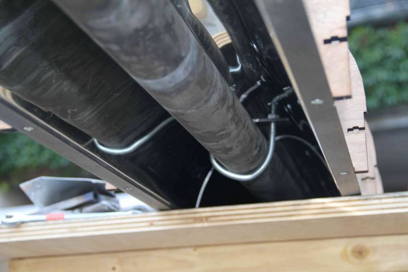
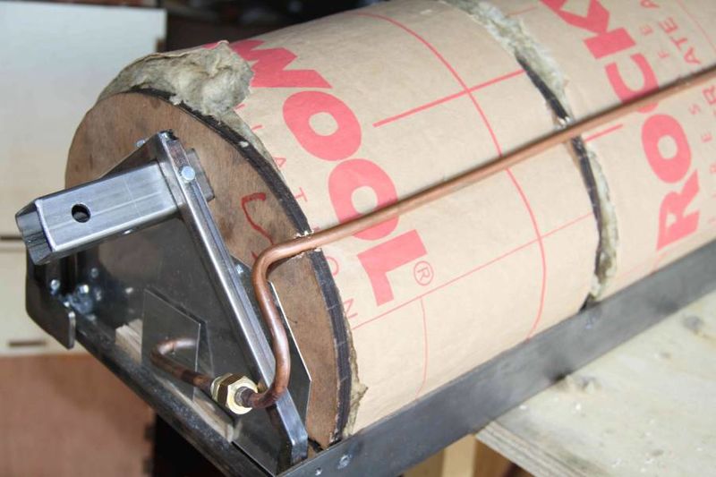
The alimentation tube for water is inside the receiver as depicted in the photo. We can make the necessary notches in the hanger with a drill. (Improvement: include the notches in the cutting plan of the hanger). Make sure that the connection elements from the south part are well sized: the surfaces have to be parallel without forcing them. This will allow obtaining the sealing of the south connection. The plumbing elements should be able to be included inside the receiver.
Étape 11 - Sealing with the cover
We can use a cover, made of one piece of fine metal sheet with a width of 700mm and a length of 2100mm, or several pieces connected one to each other. Drill the cover in order to fix the holes of the L. We can trust the plan, or position on a table the Ls on the cover. Mark the position of the holes. Drill the holes having a diameter of 4 mm. Put here the cover on the receiver. Screw one by one and begin from one side in order to finish to the opposite side. Adjust correctly the position of the holes in the cover. While putting the screws, add the spacers.
Add the thermal insulation on the extremities of the receiver. Seal the cover on the edges: cut a metal sheet having the shape of a hanger, using a shape of a hanger or the negative of it. Adjust the position of the holes in the cover. Add the horizontal metal sheet that will be blocked between the Ls, in order to seal the lower part of the receiver beyond the glass.
Étape 12 - Setting up the glass (with a junction under and above)
Before putting the glass, check the fittings’ sealing on the way out of the absorber tube. Rise the pressure in tube with a bike pump. Find the holes with soapy water.
Put the receiver, with the secondary reflector upside-down. Unscrew in the 4 coins the two fixation screw placed between the L’s and the junctions. Put the Ls on the table, letting the cover attached. Put a bead of glazier sealant (or high temperature sealant), preferably white, on the perimeter of the secondary reflector: laterally, on the metallic flat fixing the CPC, on the hangers and eventually on the extremities, without dirtying the reflector. Put the glass on the bead of sealant, to close the cavity of the secondary reflector. Add another bead of sealant on the edges of the glass. Reposition the Ls and screw them.
Turn the receiver by suspending it on its extremities. Check that the glass is still centered. Let it dry.
Étape 13 - Placing the receiver
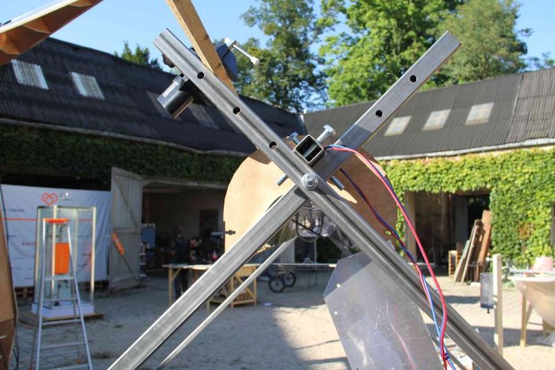
Two persons must carry the receiver, by taking it of the central beam. Put it on the tepee. Pass on the screws. Widen the holes or use smaller screw if necessary.
Étape 14 - Points to improve
To drill the slotted holes without damaging the driller, drill two holes by punching the center of the holes at a distance of 3 mm (the second hole is often less successful, a soft clipping may improve the result ) or 4 mm (the clipping is necessary to remove the material between the holes).
Hole position: maybe drill the holes after drilling the flat? Normally, the slotted holes give already a margin.
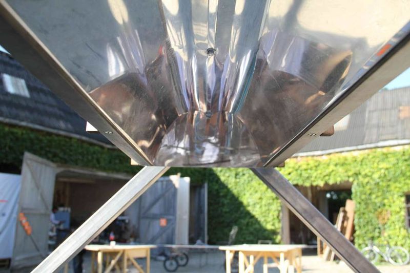
Folding the secondary reflector can be improved. The mirror sheet is difficult to work with, especially in its central part. With the proposed method, the mirror doesn’t follow perfectly the shape of the hanger on its central part. Another idea is to work separately the two scrolls to form easier the strong bending in the center. The central fold should be formed after the bending.
In the method presented, the central bending being difficult to obtain, the necessary central fold is less important. We propose to give a smaller angle compared to the theoretical shape, the angle of 45°. By giving the theoretical angle of 90°, the reflector might break during the assemblage because of the sudden unfold to adjust on the hanger.
Folding with a machine is not good enough. After during our test, the fold is not sharp-edged. The machine might twist the mirror in an unwanted direction.
For the clamped bending, a 5 cm tube (instead of 4 cm) might as well be used. This would allow to the receiver tube.
Position of the square tube: by putting it on the flat, instead of the point allows to reduce the height of the CPC and even the rigidity of the hangers.


 Français
 English
 Deutsch
 Español
 Italiano
 Português