Sommaire
- 1 Introduction
- 2 Étape 1 - Top and Bottom Plates (grid structure 1)
- 3 Étape 2 - Top and Bottom Plates (grid structure 2)
- 4 Étape 3 - Leg Linear Rail Prep
- 5 Étape 4 - Leg linear Rail install
- 6 Étape 5 - Leg install 1
- 7 Étape 6 - Leg Install 2
- 8 Étape 7 - (potential) Preparing the heating element bands
- 9 Commentaires
Introduction
Matériaux
Outils
Étape 1 - Top and Bottom Plates (grid structure 1)
*The following 2 steps will be used to make 2 identical plate assemblies. The parts listed are for 1 assembly (so double everything if you're making two plates at a time)
Tools
1/4"-20 tap + tap handle
countersink (or anything over 1/4" bit) for hole cleanup
13mm Socket
Parts
1 meter aluminum sheet
2x 1000mm 4080 extrusion
4x 920mm 4080 extrusion
4x 286mm 4080 extrusion
2x266mm 4080 extrusion
156 T-nuts (16*9) + 12)
156 M8x16mm Bolts
156 M8 washers
Steps
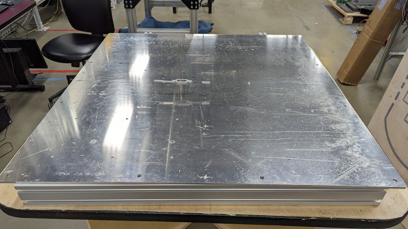
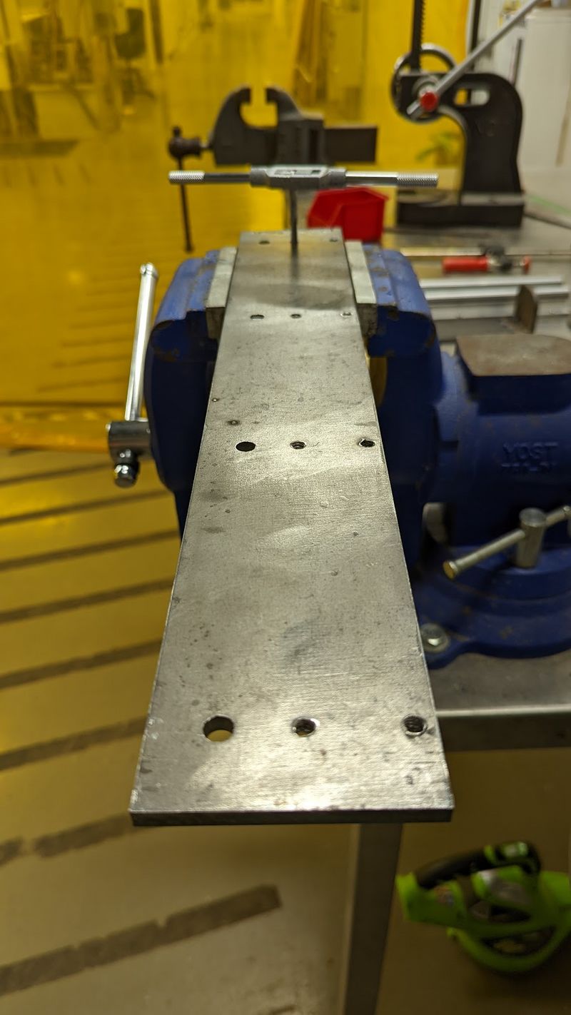
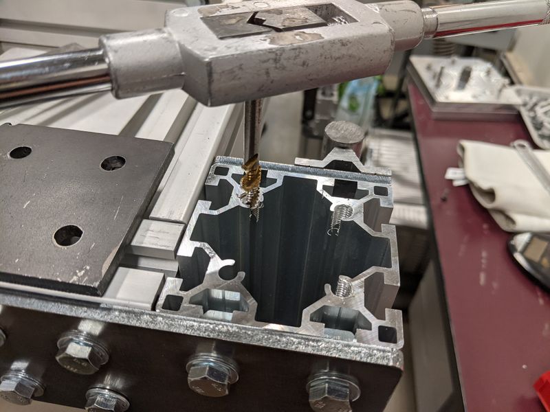
- Tap the 36 pre-drilled 13/64" holes with the 1/4"-20 tap.
- use the countersink bit to clean up any debris.
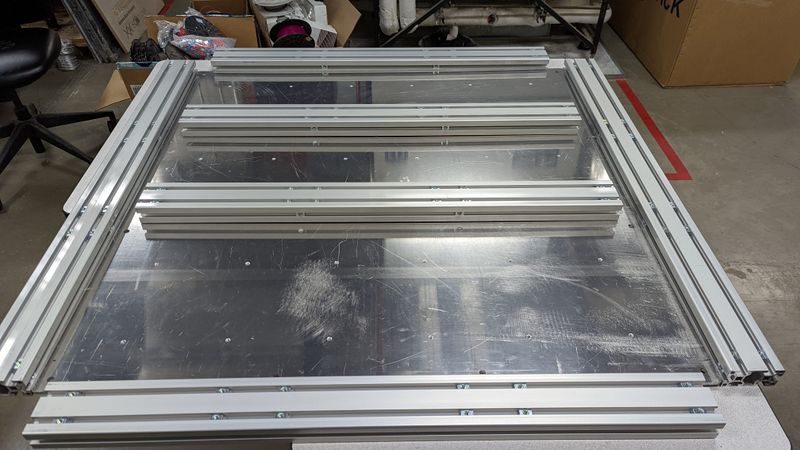
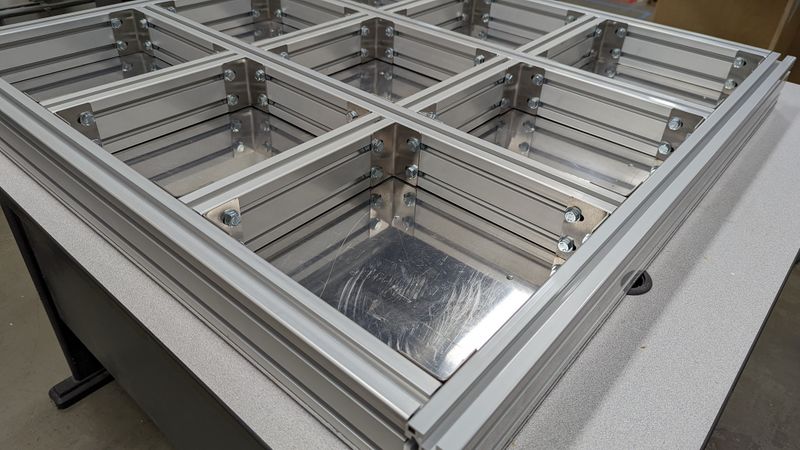
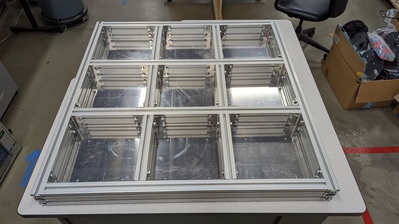
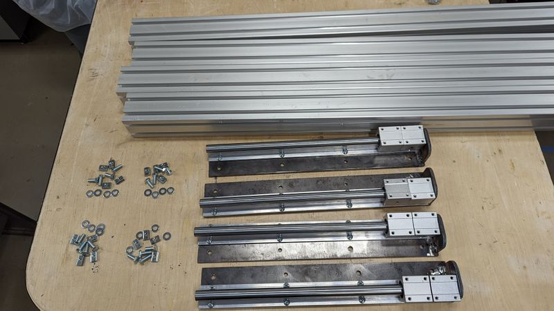
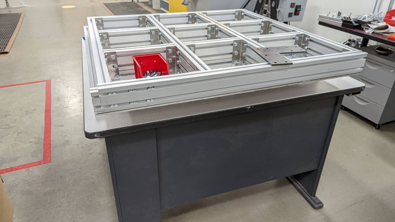
- Layout the large extrusion (image 2) so that the 1m sides are parallel, and the 960mm beams are evenly distributed at 90 degrees to the 1m beams.
- Insert 12 t-nuts (6 in each row) into each extrusion face that faces the inside of the plate. (image 2). 8 faces total(4 from exterior beams, and 4 from each side of the two interior beams. 96 nuts total
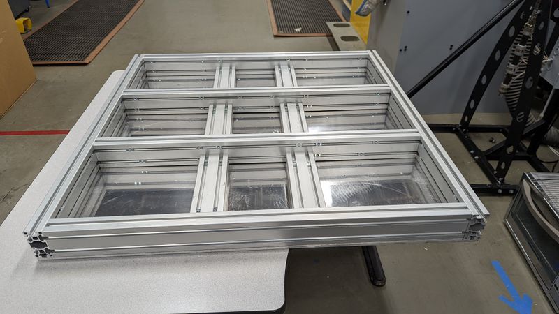
- Position the two 266mm beams in the center row, splitting it into 3 equal sections.
- Position the four 286mm beams in the top and bottom rows, matching the position of the 266 beams.
- For each 80mm face of these interior beams, place 4 t nuts (2 in each slot). Be sure to place these on both faces. 48 nuts total.
Attaching the exterior beams to the plate
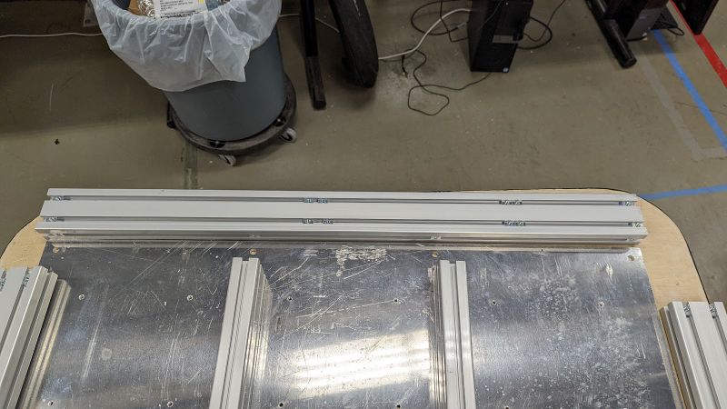
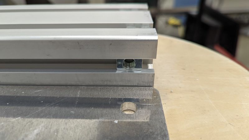
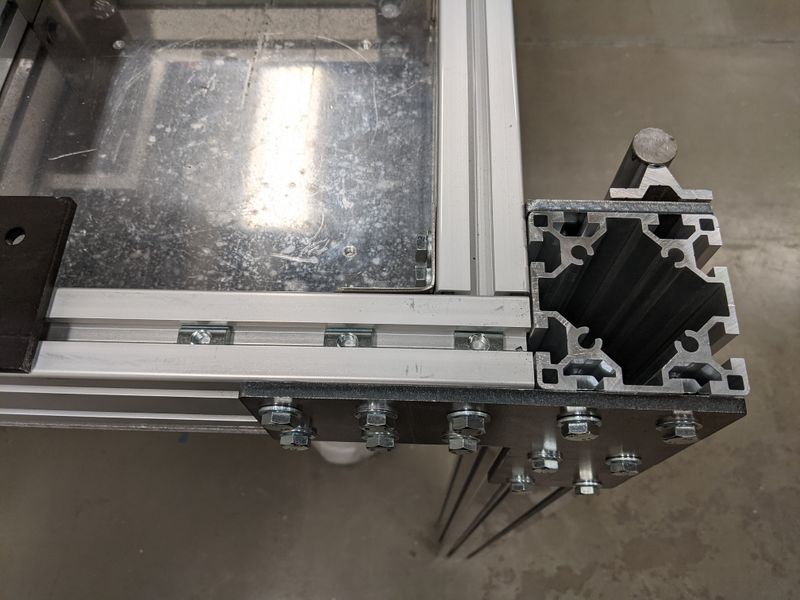
- On the bottom 40mm face, slide 4 t nuts into each 1000mm beam. (image 4)
- Match these T nuts with the holes in the plate as this will be a "blind" install. (image 5)
- slide the plate off your work area so you can access the holes from below.
- Place the extrusion directly on top of the plate ensuring not to shift it off its alignment.
- Using the M8 bolts, secure the beam to the plate.
- Repeat this process until you have attached both 1000mm beams and 960mm beams. (12 bolts total)
Étape 2 - Top and Bottom Plates (grid structure 2)
Tools
same as above
Parts
36 corner brackets
Steps
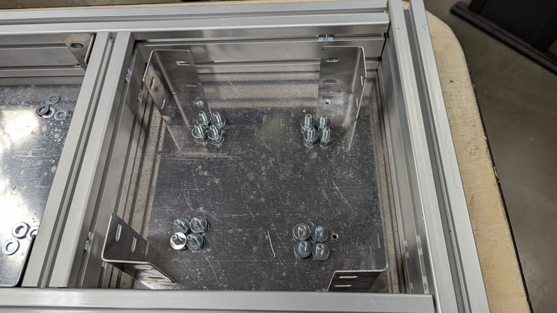
- Prepare your parts. Each "cell" will require 4 brackets, 16 M8Bolts, and 16 washers
- Starting with the 4 corners of the entire assembly, attach the corner brackets and tighten the bolts only to finger-tight.
- Next attach the 920 beam ends to the outer perimeter.
- Next, attach the inner beams in place. Ensure that all beams are equally spaced. (remember that the 2 interior beams are shorter though)
Étape 3 - Leg Linear Rail Prep
Tools
(welder?)
Drill press
Grinder
Vice
1/4-20 Tap
Parts
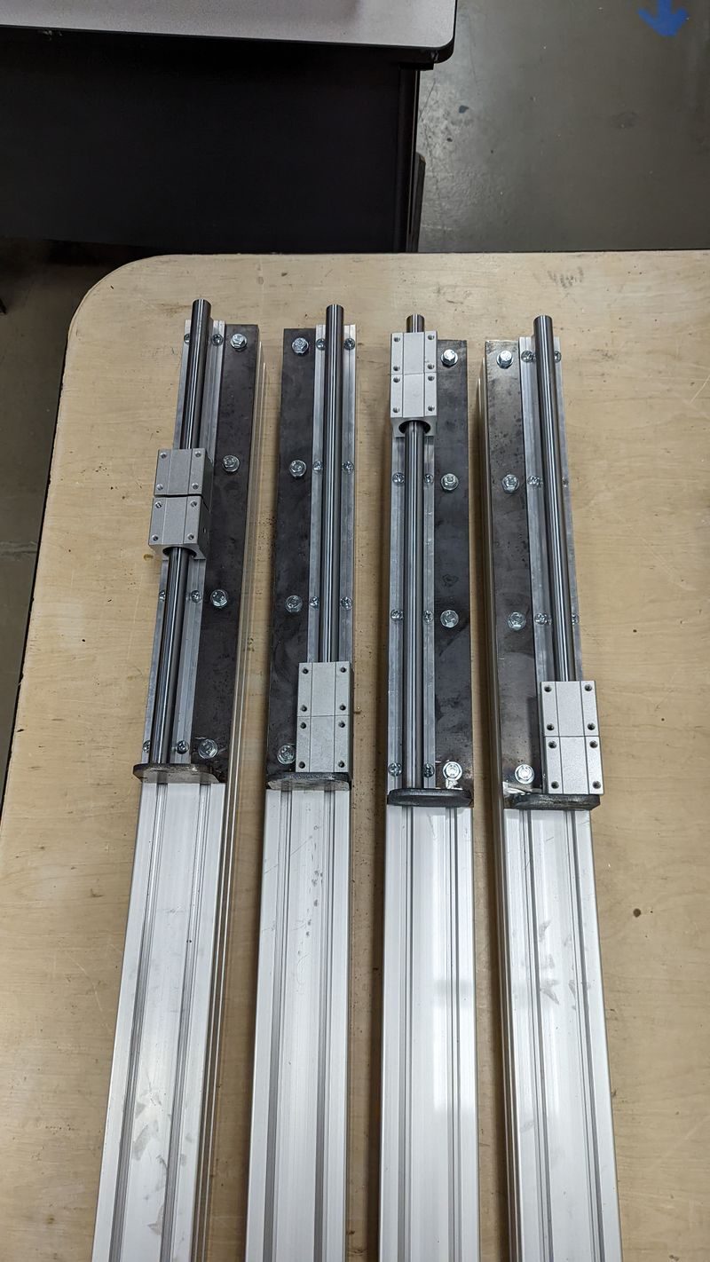
4x Linear rail plates (w/ 90degree stopper plate)
4x Linear rail posts
16x 1/4"-20 x 3/8" bolts
Steps
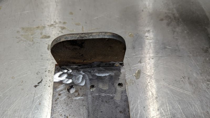
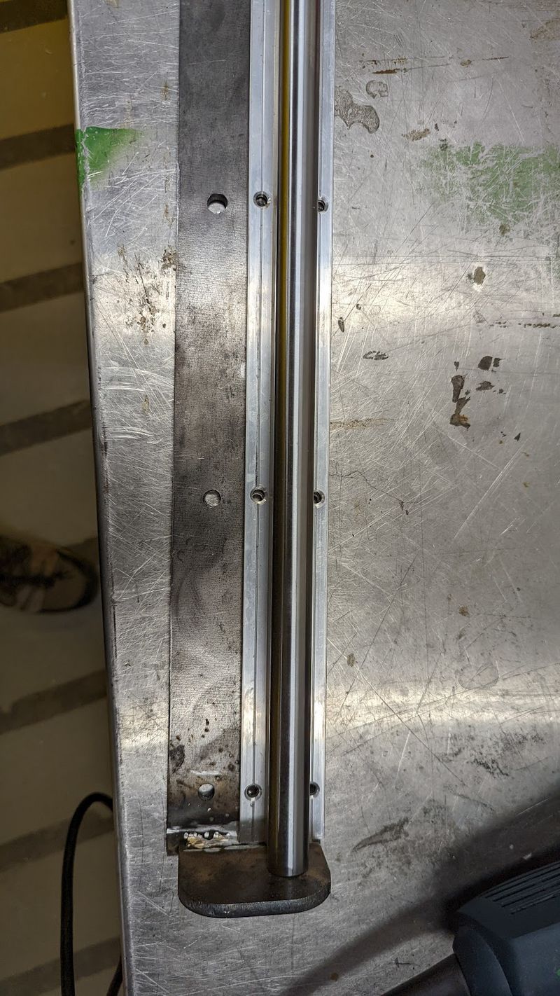
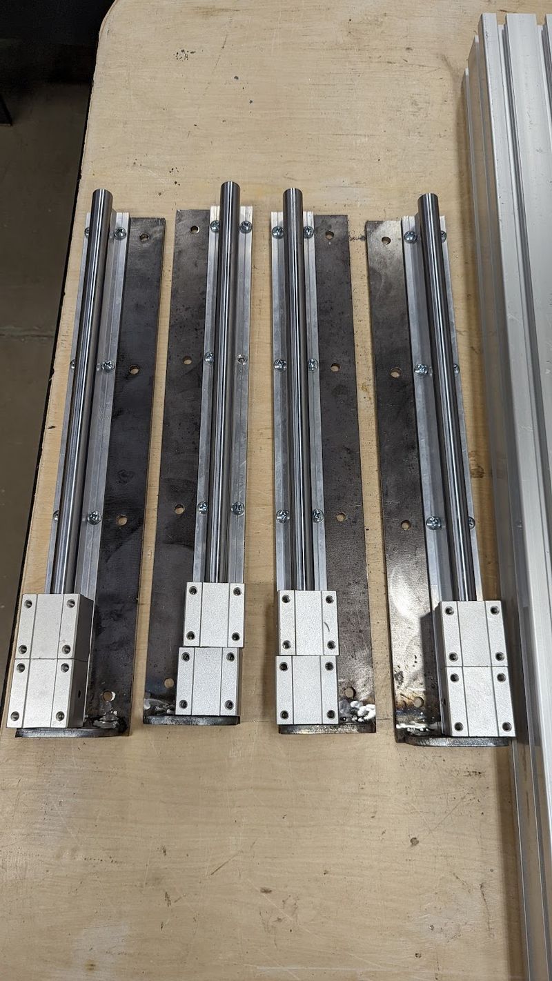
- (if not already done) weld the small stopper plate to the end of the long linear rail leg plate. Be sure you have two mirrored sets and not four identical pieces. (see image 5)
- Grind down the welds (or avoid welding where the linear slide will attach.) This is a very snug fit and you may have to make some room for proper alignment
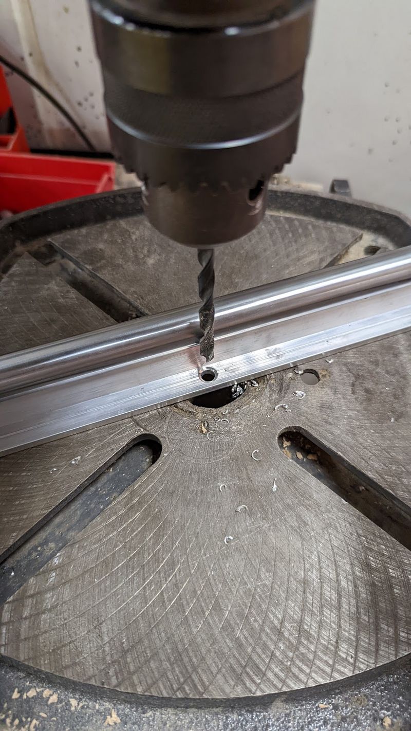
- You can also drill out the slide rail mounting holes (aluminum) to give yourself a little more room for a proper fit.
- Image 4 shows the holes not in perfect alignment, so you may have to grind the linear rail bar down until the wholes are perfectly aligned.
- Tap all 8 small holes to 1/4"-20
- Align and install the linear rail to the plate. Add the bearing carriages. (repeat for all 4 plates)
Étape 4 - Leg linear Rail install
Tools
13mm socket
Parts
16x m8x20 bolts
16x m8 washers
16x m8 t-nuts
4x 8080 extrusion
Steps
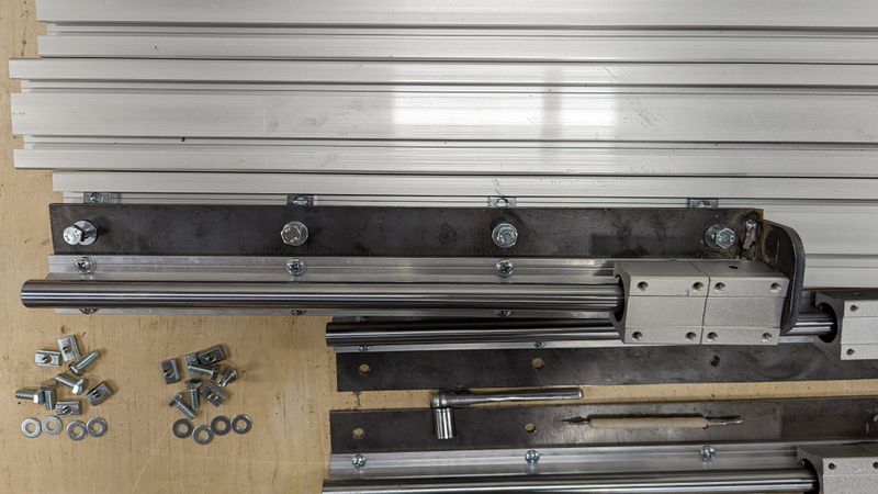
- Slide 4 t nuts into the 8080 extrusion rail.
- Position one linear slide just next to the rail so you can align the t-nuts to the holes as this will again be a "blind" install.
- Attach the linear slide so it is flush with the end of the extrusion.
- repeat for all 4 rails so you have 2 mirrored pairs.
Étape 5 - Leg install 1
Tools
13mm socket
At least 2, better with 3, people
Clamps
Parts
Top plate assembly
4x legs
4x corner plates (12-hole, shaped like a 7)
48x m8x20 bolts
48x m8 t nuts
48x m8 washers
Steps
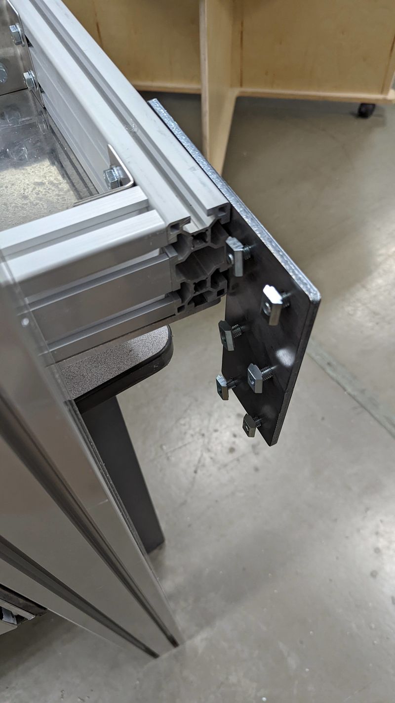
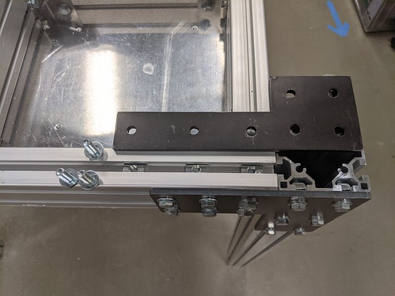
- Slide 6 t-nuts (3 in each channel) in the corner of the top plate assembly. Align the holes with the corner plate pattern, preparing for a blind fit.
- Attach the plate with bolts/washers loosely. *there are a few ways you could do this next section, but we found this method to be effective with only 2 people, but we recommend using more! *
- Place 6 more bolts/washers in the open section of the support plate, and loosely screw on t-nuts for only a thread or two. You want these to be flexible.
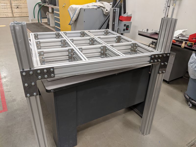
- Person A: Lift the leg directly above the plate and do your best to "Float" the leg so it is weightless for person B
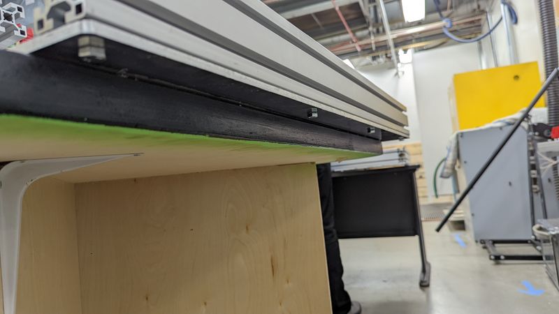
- Person B: thread the channels on the leg over the pre-positioned t-nuts, 2 at at time, until the leg drops down into position (image 3)
- Repeat for all 4 legs. At this point the top assembly should still be supported by the table below. Get your third person ready.
- Have two people lift the top assembly so it slides up the rails until it is flush with the top of the leg extrusions.
- Have your third person tighten down at least 2 bolts on all 4 corners, transferring the weight to the legs.
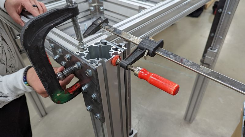
- Use clamps to secure all beams into a flush position, then tighten down all bolts.
Étape 6 - Leg Install 2
Tools
13mm socket
8mm tap and tappinghandle
Parts
Top plate assembly
4x Brackets (b/p shaped)
28x m8x20 (or 16)
28x m8 washers
12x t-nuts (post assembly)
Steps
- Tap the exposed interior channels at the top of the legs with the 8mm tap.
- insert 3 t-nuts into the horizontal extrusion channel that terminates at the leg.
- Use the the b/p bracket to align the placement of the t-nuts.
- Secure the bracket in place by blind capturing the 3 nuts, and using the 4 tapped channels.
Repeat for all 4 legs.
Étape 7 - (potential) Preparing the heating element bands
Tools
Sheet Break
Parts
18x steel strips
Steps
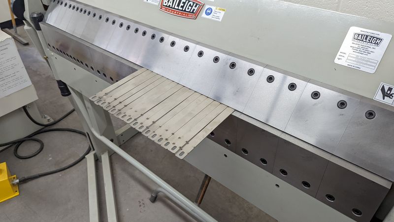
- Locate the small holes on the steel strips. These mark where the bends will take place. However, if you do not account for the thickness of your material, you may created bands that are too small/tight.
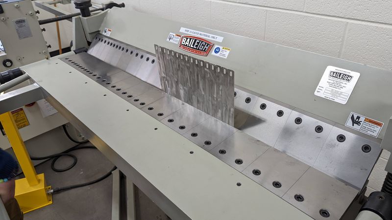
- Position the straps on the sheet break so you can see all 4 sets of indicators. We will bend them in this top down order.
- Bend at 90 degrees on the first indicator mark.
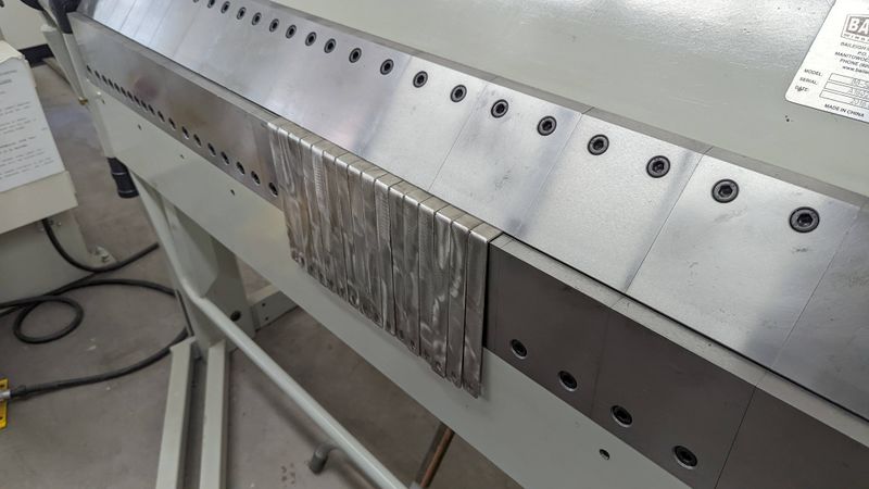
- Flip over 180 degrees so the straps match Image 3.
- Bend again at 90.
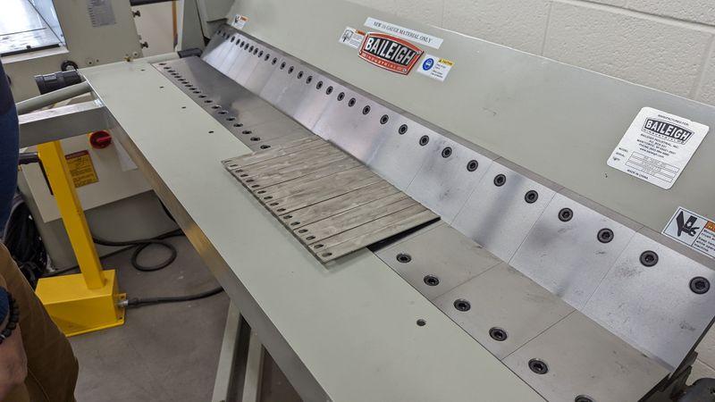
- remove the straps and check them on a heating element.
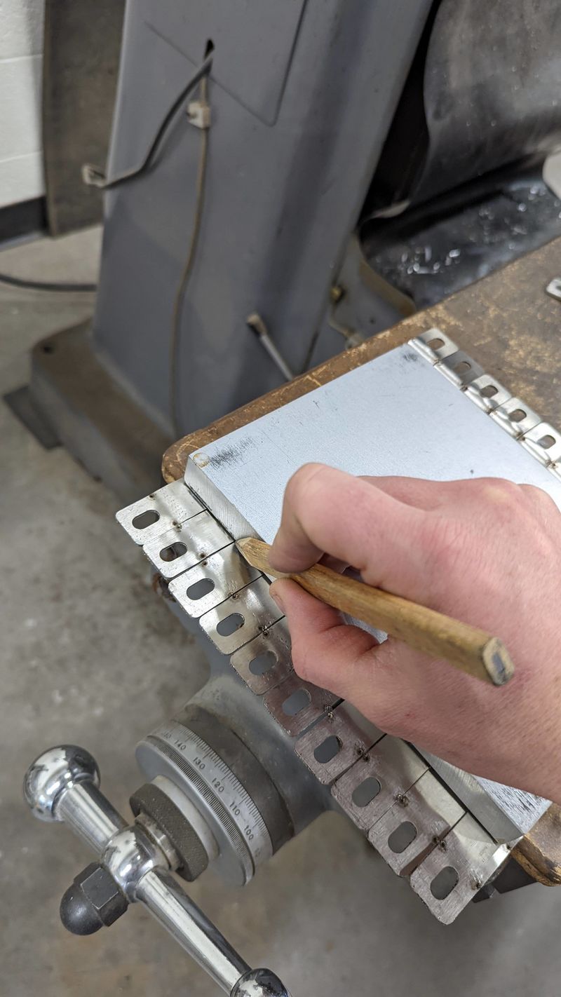
- Do the bend indicators leave you enough room to make another bend? if not, you may need to bend PAST the indicators. In image 5 we had to adjust the bend location and marked it with a pencil.
- Flip the bands around and repeat the process. ***Be sure to test fit your 1st band before bending all the others.
- TYLER INSERT GIF HERE
Published

 Français
 English
 Deutsch
 Español
 Italiano
 Português