(Imported page from en.wikifab.org) |
(convert properties for internationnalized Wikifab) |
||
| Ligne 1 : | Ligne 1 : | ||
| − | {{Tuto Details | + | {{ {{tntn|Tuto Details}} |
|SourceLanguage=en | |SourceLanguage=en | ||
|Language=en | |Language=en | ||
| Ligne 5 : | Ligne 5 : | ||
|Type=Creation | |Type=Creation | ||
|Area=Energy, Food and Agriculture, Science and Biology | |Area=Energy, Food and Agriculture, Science and Biology | ||
| − | |Description=It is about a coffee roaster that works with solar energy. The solar energy is collected by a Scheffler concentrator, a very good open-source technology, used since a while worldwide to cook. [http://www.solare-bruecke.org/index.php/en/die-scheffler-reflektoren This page explains the working principle of the Scheffler concentrator.] | + | |Description=<translate>It is about a coffee roaster that works with solar energy. The solar energy is collected by a Scheffler concentrator, a very good open-source technology, used since a while worldwide to cook. [http://www.solare-bruecke.org/index.php/en/die-scheffler-reflektoren This page explains the working principle of the Scheffler concentrator.] |
The solar energy enters directly in the roaster, where the beans are placed. We can roast coffee beans (around 230°C), cacao beans (around 160°C) and even make pop-corn !… | The solar energy enters directly in the roaster, where the beans are placed. We can roast coffee beans (around 230°C), cacao beans (around 160°C) and even make pop-corn !… | ||
''Translated from French by Armenia Siladi.'' | ''Translated from French by Armenia Siladi.'' | ||
| − | ''Note: [http://beta.wikifab.org/index.php/Torr%C3%A9facteur_de_caf%C3%A9_%C3%A0_%C3%A9nergie_solaire_(pour_concentrateur_de_Scheffler) La version française de ce tutoriel est disponible ici ! / the French version is here :)] '' | + | ''Note: [http://beta.wikifab.org/index.php/Torr%C3%A9facteur_de_caf%C3%A9_%C3%A0_%C3%A9nergie_solaire_(pour_concentrateur_de_Scheffler) La version française de ce tutoriel est disponible ici ! / the French version is here :)] ''</translate> |
|Difficulty=Medium | |Difficulty=Medium | ||
|Cost=500 | |Cost=500 | ||
| Ligne 19 : | Ligne 19 : | ||
|Main_Picture=CompadreRoaster 912x564.JPG | |Main_Picture=CompadreRoaster 912x564.JPG | ||
}} | }} | ||
| − | {{Introduction | + | {{ {{tntn|Introduction}} |
| − | |Introduction='''Context''' | + | |Introduction=<translate>'''Context''' |
This solar roaster was developed with GRUPO PUCP : "Grupo de apoyo al sector rural, Pontificia Universidad Catolica del Peru". This research group, supporting the rural sector, has developed technologies for rural sector for almost 20 years. After transfiguring the technology of the Scheffler concentrator in 2010, a first solar roaster was developed in 2012. The start-up Compadre improved the technology in order to reach a more ergonomic in 2014. This model is used today by the Peruvian coffee growers : it allows them to roast by themselves the coffee with solar energy. By selling their coffee with the entire added value, the coffee growers have a more valuable job. Their economical situation is getting better, because thei income is tripled. To know more about the positive social and environmental impacts of the start-up Compadre, [http://www.compadre.pe you can visit www.compadre.pe]. End of 2015, a roaster adapted to France (version having a different height of the focal point, due to the latitude difference) was designed (photo 6328). The building tutorial was written for this version, that was build from February 15 to 22, 2016. | This solar roaster was developed with GRUPO PUCP : "Grupo de apoyo al sector rural, Pontificia Universidad Catolica del Peru". This research group, supporting the rural sector, has developed technologies for rural sector for almost 20 years. After transfiguring the technology of the Scheffler concentrator in 2010, a first solar roaster was developed in 2012. The start-up Compadre improved the technology in order to reach a more ergonomic in 2014. This model is used today by the Peruvian coffee growers : it allows them to roast by themselves the coffee with solar energy. By selling their coffee with the entire added value, the coffee growers have a more valuable job. Their economical situation is getting better, because thei income is tripled. To know more about the positive social and environmental impacts of the start-up Compadre, [http://www.compadre.pe you can visit www.compadre.pe]. End of 2015, a roaster adapted to France (version having a different height of the focal point, due to the latitude difference) was designed (photo 6328). The building tutorial was written for this version, that was build from February 15 to 22, 2016. | ||
| Ligne 28 : | Ligne 28 : | ||
'''Perspectives''' | '''Perspectives''' | ||
| − | We hope this roaster will help you in a positive way and we are looking forward to sharing feedbacks and contributions to make the most of this opensource technology everywhere it is useful! | + | We hope this roaster will help you in a positive way and we are looking forward to sharing feedbacks and contributions to make the most of this opensource technology everywhere it is useful!</translate> |
}} | }} | ||
| − | {{Materials | + | {{ {{tntn|Materials}} |
| − | |Material=See photo of table. | + | |Material=<translate>See photo of table.</translate> |
|Tools=*Welding machine / safety mask | |Tools=*Welding machine / safety mask | ||
*Vice | *Vice | ||
| Ligne 67 : | Ligne 67 : | ||
}} | }} | ||
{{Separator}} | {{Separator}} | ||
| − | {{Tuto Step | + | {{ {{tntn|Tuto Step}} |
| − | |Step_Title=Cut the metal pieces (bars, flat, L profile angle) | + | |Step_Title=<translate>Cut the metal pieces (bars, flat, L profile angle)</translate> |
| − | |Step_Content=Cut the bars, the flats and the L profile angle at the lenghts marked in the following table (see image of table). | + | |Step_Content=<translate>Cut the bars, the flats and the L profile angle at the lenghts marked in the following table (see image of table).</translate> |
|Step_Picture_00=ListOfMetalPiecesToCut SolarRoaster.png | |Step_Picture_00=ListOfMetalPiecesToCut SolarRoaster.png | ||
|Step_Picture_01=IMG 6335 DecoupeMetal.JPG | |Step_Picture_01=IMG 6335 DecoupeMetal.JPG | ||
|Step_Picture_02=IMG 6336 PiecesDecoupees.JPG | |Step_Picture_02=IMG 6336 PiecesDecoupees.JPG | ||
}} | }} | ||
| − | {{Tuto Step | + | {{ {{tntn|Tuto Step}} |
| − | |Step_Title=Cut the metal sheet | + | |Step_Title=<translate>Cut the metal sheet</translate> |
| − | |Step_Content=Cut the sheet metal according to the drawn pattern [https://cad.onshape.com/documents/179f7be4cbe6f9f9428b8739 available here on OnShape]. A preview of the schema is also here together with the photos. Use preferably the jigsaw (at default, the disk unit, but the cutting wears out the cutting disk...) | + | |Step_Content=<translate>Cut the sheet metal according to the drawn pattern [https://cad.onshape.com/documents/179f7be4cbe6f9f9428b8739 available here on OnShape]. A preview of the schema is also here together with the photos. Use preferably the jigsaw (at default, the disk unit, but the cutting wears out the cutting disk...)</translate> |
|Step_Picture_00=IMG 20160216 195723 DecoupeToleAcier.jpg | |Step_Picture_00=IMG 20160216 195723 DecoupeToleAcier.jpg | ||
|Step_Picture_01=IMG 20160216 203150 DecoupeToleAcier-PatronTambour.jpg | |Step_Picture_01=IMG 20160216 203150 DecoupeToleAcier-PatronTambour.jpg | ||
| Ligne 82 : | Ligne 82 : | ||
|Step_Picture_03=ApercuSchemaDecoupeTole PourTorrefacteurSolaire.png | |Step_Picture_03=ApercuSchemaDecoupeTole PourTorrefacteurSolaire.png | ||
}} | }} | ||
| − | {{Tuto Step | + | {{ {{tntn|Tuto Step}} |
| − | |Step_Title=Support : Base (socle) 1/2 | + | |Step_Title=<translate>Support : Base (socle) 1/2</translate> |
| − | |Step_Content=Gather : | + | |Step_Content=<translate>Gather : |
the 5 pieces of the support base, L profile angle, having the dimensions 35x35, | the 5 pieces of the support base, L profile angle, having the dimensions 35x35, | ||
the 2 flat pieces for the support base, having the dimensions 25x4 | the 2 flat pieces for the support base, having the dimensions 25x4 | ||
| Ligne 93 : | Ligne 93 : | ||
The transversal bars will be the support of the central beam. Firstly, weld on each side the little bars of 25 mm, on the L profile angle ( the photo 165503 show the pieces before the positioning and the welding). Weld the transversal bars on the little bars ; by setting-up this way, we can screw the beam to the socle without problems. We obtain the socle as shown in picture 174618. | The transversal bars will be the support of the central beam. Firstly, weld on each side the little bars of 25 mm, on the L profile angle ( the photo 165503 show the pieces before the positioning and the welding). Weld the transversal bars on the little bars ; by setting-up this way, we can screw the beam to the socle without problems. We obtain the socle as shown in picture 174618. | ||
| − | Comment : the gravity center of the drum is in front of the support base. We can improve the construction by moving back a little the transversal bars. However, it will be difficult to put the cooler back enough so that it should be under the drum. So, it is easier to stabilize the base with a counterweight : the battery is already helping doing that. | + | Comment : the gravity center of the drum is in front of the support base. We can improve the construction by moving back a little the transversal bars. However, it will be difficult to put the cooler back enough so that it should be under the drum. So, it is easier to stabilize the base with a counterweight : the battery is already helping doing that.</translate> |
|Step_Picture_00=IMG 20160215 162351 CadreBaseSoudure.jpg | |Step_Picture_00=IMG 20160215 162351 CadreBaseSoudure.jpg | ||
|Step_Picture_01=IMG 20160215 163031 CadreBaseSoudureFin.jpg | |Step_Picture_01=IMG 20160215 163031 CadreBaseSoudureFin.jpg | ||
| Ligne 99 : | Ligne 99 : | ||
|Step_Picture_03=IMG 20160215 174618 BaseSoudee.jpg | |Step_Picture_03=IMG 20160215 174618 BaseSoudee.jpg | ||
}} | }} | ||
| − | {{Tuto Step | + | {{ {{tntn|Tuto Step}} |
| − | |Step_Title=Support : Base (socle) 2/2 | + | |Step_Title=<translate>Support : Base (socle) 2/2</translate> |
| − | |Step_Content=Add the two leg fixation for the cooler (two flat pieces having the dimensions 25x3 : (or the connection to Scheffler) having a length of 72 mm). Drill two holes of 6mm, centered on the width, at 15 mm (and at 35 mm from the edge for the direct connection to Scheffler) ; keep them at a distance of 50mm with a clamp (photo 190655). Weld them vertically at the base by positioning as shown in photo 190558, in order to obtain the result illustrated by photo 191519. | + | |Step_Content=<translate>Add the two leg fixation for the cooler (two flat pieces having the dimensions 25x3 : (or the connection to Scheffler) having a length of 72 mm). Drill two holes of 6mm, centered on the width, at 15 mm (and at 35 mm from the edge for the direct connection to Scheffler) ; keep them at a distance of 50mm with a clamp (photo 190655). Weld them vertically at the base by positioning as shown in photo 190558, in order to obtain the result illustrated by photo 191519. |
| − | Comment : it might be necessary to cut slantwise the external superior angle of these legs (cut at 45°, 10 mm from the edge-side), to allow bringing closer the cooler and to avoid a blockage while the drum is rotating... | + | Comment : it might be necessary to cut slantwise the external superior angle of these legs (cut at 45°, 10 mm from the edge-side), to allow bringing closer the cooler and to avoid a blockage while the drum is rotating...</translate> |
|Step_Picture_00=IMG 20160215 190655 PattesFixationRefroidisseur-MaintienAvantSoudure.jpg | |Step_Picture_00=IMG 20160215 190655 PattesFixationRefroidisseur-MaintienAvantSoudure.jpg | ||
|Step_Picture_01=IMG 20160215 190558 PattesFixationRefroidisseur-PositionnementPourSoudureSurBase.jpg | |Step_Picture_01=IMG 20160215 190558 PattesFixationRefroidisseur-PositionnementPourSoudureSurBase.jpg | ||
|Step_Picture_02=IMG 20160215 191519 BaseSoudeeAvecPattesFixationRefroidisseur.jpg | |Step_Picture_02=IMG 20160215 191519 BaseSoudeeAvecPattesFixationRefroidisseur.jpg | ||
}} | }} | ||
| − | {{Tuto Step | + | {{ {{tntn|Tuto Step}} |
| − | |Step_Title=Support: beam | + | |Step_Title=<translate>Support: beam</translate> |
| − | |Step_Content=Gather : | + | |Step_Content=<translate>Gather : |
the pipe 50x50 (the central beam) | the pipe 50x50 (the central beam) | ||
the two flats of 50x8 and the length of 140 mm (low fixation central beam) | the two flats of 50x8 and the length of 140 mm (low fixation central beam) | ||
the little flat of 50x8 and the length of 70 mm (reinforcements to keep the central beam at the right angle ) | the little flat of 50x8 and the length of 70 mm (reinforcements to keep the central beam at the right angle ) | ||
| − | Cut the beam with an angle of 25° on one side (this will be the lower part). | + | Cut the beam with an angle of 25° on one side (this will be the lower part).</translate> |
|Step_Picture_00=IMG 20160220 224919 SupportAssemble.jpg | |Step_Picture_00=IMG 20160220 224919 SupportAssemble.jpg | ||
|Step_Picture_01=IMG 20160218 213059 ElementsDuSupport-Base-Mat-AxeEtBras.jpg | |Step_Picture_01=IMG 20160218 213059 ElementsDuSupport-Base-Mat-AxeEtBras.jpg | ||
}} | }} | ||
| − | {{Tuto Step | + | {{ {{tntn|Tuto Step}} |
| − | |Step_Title=Support : Prepare the montage base + beam 1/2 | + | |Step_Title=<translate>Support : Prepare the montage base + beam 1/2</translate> |
| − | |Step_Content=The little flat having the length of 70 mm serve as reinforcement and helps to position the beam at the right inclination. It must be cut in two triangles and afterward in other two parts, by following the angle of 65° (90-25) as shown in photo 6343 + 6345. | + | |Step_Content=<translate>The little flat having the length of 70 mm serve as reinforcement and helps to position the beam at the right inclination. It must be cut in two triangles and afterward in other two parts, by following the angle of 65° (90-25) as shown in photo 6343 + 6345. |
The beam is fixed on two pieces of flat 50x8, having the length of 140mm. Mark these pieces, as shown on photo 182444, in order to see the beam limits. | The beam is fixed on two pieces of flat 50x8, having the length of 140mm. Mark these pieces, as shown on photo 182444, in order to see the beam limits. | ||
Drill with a drill having the diameter of 10mm, at 125 mm from the edge, on each angle. | Drill with a drill having the diameter of 10mm, at 125 mm from the edge, on each angle. | ||
| Ligne 125 : | Ligne 125 : | ||
Idea : we can connect the two flats with two welding points, as shown in photo 182603, in order to drill the 4 holes only two times. | Idea : we can connect the two flats with two welding points, as shown in photo 182603, in order to drill the 4 holes only two times. | ||
Weld the two flats together, one side next to the other (photo 104043). | Weld the two flats together, one side next to the other (photo 104043). | ||
| − | Note : On the photo 104043, the metal is cleaned in order to help the beam welding that is seen at the left. | + | Note : On the photo 104043, the metal is cleaned in order to help the beam welding that is seen at the left.</translate> |
|Step_Picture_00=IMG 6343 DecoupeRenfortBasMat.JPG | |Step_Picture_00=IMG 6343 DecoupeRenfortBasMat.JPG | ||
|Step_Picture_01=IMG 6345 DecoupeRenfortBasMat.JPG | |Step_Picture_01=IMG 6345 DecoupeRenfortBasMat.JPG | ||
| Ligne 132 : | Ligne 132 : | ||
|Step_Picture_04=IMG 20160216 104043 PlatsBasMatSoudes.jpg | |Step_Picture_04=IMG 20160216 104043 PlatsBasMatSoudes.jpg | ||
}} | }} | ||
| − | {{Tuto Step | + | {{ {{tntn|Tuto Step}} |
| − | |Step_Title=Support : Prepare the montage base + beam 2/2 | + | |Step_Title=<translate>Support : Prepare the montage base + beam 2/2</translate> |
| − | |Step_Content=Position the double flat on the socle as shown by the photo 193701. Mark with a punch the holes position in the transversal L profile angle. Drill the transversal L profile angle (photo 194134). | + | |Step_Content=<translate>Position the double flat on the socle as shown by the photo 193701. Mark with a punch the holes position in the transversal L profile angle. Drill the transversal L profile angle (photo 194134). |
| − | Position and weld the beam on the double flat, with the reinforcements, as suggested by photo 6350. We have the photo 114248, where the beam is in its position on the socle. | + | Position and weld the beam on the double flat, with the reinforcements, as suggested by photo 6350. We have the photo 114248, where the beam is in its position on the socle.</translate> |
|Step_Picture_00=IMG 20160215 193701 PositionnementPlatBasMatSurSoclePourPercage.jpg | |Step_Picture_00=IMG 20160215 193701 PositionnementPlatBasMatSurSoclePourPercage.jpg | ||
|Step_Picture_01=IMG 20160215 194134 PercageTrousFixationSoclePourMat.jpg | |Step_Picture_01=IMG 20160215 194134 PercageTrousFixationSoclePourMat.jpg | ||
| Ligne 141 : | Ligne 141 : | ||
|Step_Picture_03=IMG 20160216 114248 MatSurSocle.jpg | |Step_Picture_03=IMG 20160216 114248 MatSurSocle.jpg | ||
}} | }} | ||
| − | {{Tuto Step | + | {{ {{tntn|Tuto Step}} |
| − | |Step_Title=Support : Prepare the montage beam+ drill axis 1/3 | + | |Step_Title=<translate>Support : Prepare the montage beam+ drill axis 1/3</translate> |
| − | |Step_Content=Make on opening in the beam, having 50 mm height and taking the entire width of the square pipe. The lower part of the opening is 382,5 mm, measured from the low level (the longest side, on the cut at 25°, see measure shown on the schema), as shown by the photo 121247. | + | |Step_Content=<translate>Make on opening in the beam, having 50 mm height and taking the entire width of the square pipe. The lower part of the opening is 382,5 mm, measured from the low level (the longest side, on the cut at 25°, see measure shown on the schema), as shown by the photo 121247. |
Warning : the two openings have to be in front of each other, in order to put the round pipe perpendicularly to the beam. This will assure the right inclination of the drum. | Warning : the two openings have to be in front of each other, in order to put the round pipe perpendicularly to the beam. This will assure the right inclination of the drum. | ||
Note : we would rather open a square in the front and back side of the square tube (side on the first plane on the photo 131754 in following step), so not to weaken the structure tube. We would not cut on the edge, side on the first plane on the photo 131839 in following step. | Note : we would rather open a square in the front and back side of the square tube (side on the first plane on the photo 131754 in following step), so not to weaken the structure tube. We would not cut on the edge, side on the first plane on the photo 131839 in following step. | ||
| − | This opening allows to insert the round pipe having an external diameter of 49 mm (photo 121301). However, the hole must be broaden. | + | This opening allows to insert the round pipe having an external diameter of 49 mm (photo 121301). However, the hole must be broaden.</translate> |
|Step_Picture_00=IMG 20160216 121247 MatEvidePourPassageTubeAxe.jpg | |Step_Picture_00=IMG 20160216 121247 MatEvidePourPassageTubeAxe.jpg | ||
|Step_Picture_01=SchemaPLAN ManuelTorrefacteur.jpg | |Step_Picture_01=SchemaPLAN ManuelTorrefacteur.jpg | ||
| Ligne 153 : | Ligne 153 : | ||
|Step_Picture_04=IMG 20160216 121301 MatEvideEtTubePourAxe.jpg | |Step_Picture_04=IMG 20160216 121301 MatEvideEtTubePourAxe.jpg | ||
}} | }} | ||
| − | {{Tuto Step | + | {{ {{tntn|Tuto Step}} |
| − | |Step_Title=Support : Prepare the montage beam+ drill axis 2/3 | + | |Step_Title=<translate>Support : Prepare the montage beam+ drill axis 2/3</translate> |
| − | |Step_Content=Separate the metal sheet by using the bar with 20 mm diameter, as shown on the 123425_1 123528_1 123600. Separate enough until the round tube is entering (photo 124610). | + | |Step_Content=<translate>Separate the metal sheet by using the bar with 20 mm diameter, as shown on the 123425_1 123528_1 123600. Separate enough until the round tube is entering (photo 124610). |
| − | Adjust the sides of the squared pipe to the round pipe with a hammer. If the montage is not fixed on its height, the round tube has to be aligned on the lower part of the opening (side measured of 382,5mm) (photo 124718). | + | Adjust the sides of the squared pipe to the round pipe with a hammer. If the montage is not fixed on its height, the round tube has to be aligned on the lower part of the opening (side measured of 382,5mm) (photo 124718).</translate> |
|Step_Picture_00=IMG 20160216 123425 1 EcartementParoisMatEvide.jpg | |Step_Picture_00=IMG 20160216 123425 1 EcartementParoisMatEvide.jpg | ||
|Step_Picture_01=IMG 20160216 123528 1 EcartementParoisMatEvideZoom.jpg | |Step_Picture_01=IMG 20160216 123528 1 EcartementParoisMatEvideZoom.jpg | ||
| Ligne 164 : | Ligne 164 : | ||
|Step_Picture_04=IMG 20160216 124718 TubePourAxeTambourAjusteDansMatEvide.jpg | |Step_Picture_04=IMG 20160216 124718 TubePourAxeTambourAjusteDansMatEvide.jpg | ||
}} | }} | ||
| − | {{Tuto Step | + | {{ {{tntn|Tuto Step}} |
| − | |Step_Title=Support : Prepare the montage beam+ drill axis 3/3 | + | |Step_Title=<translate>Support : Prepare the montage beam+ drill axis 3/3</translate> |
| − | |Step_Content=Drill the round pipe and the square pipe with two holes on each side : diameter of 6 mm, distance of 20mm (photo 131839). Drill the two pieces together in order to have a good alignment. Once a side is drilled, fix the two pieces with two bolds and drill the other side (photo 131754). | + | |Step_Content=<translate>Drill the round pipe and the square pipe with two holes on each side : diameter of 6 mm, distance of 20mm (photo 131839). Drill the two pieces together in order to have a good alignment. Once a side is drilled, fix the two pieces with two bolds and drill the other side (photo 131754). |
Warning : verify the pipe position in the lower part of the opening, on each side. This will ensure the good inclination of the axis, and consequently, of the drum. | Warning : verify the pipe position in the lower part of the opening, on each side. This will ensure the good inclination of the axis, and consequently, of the drum. | ||
| Ligne 173 : | Ligne 173 : | ||
Fix by welding a bearing at each extremity of the round tube, on the interior side. | Fix by welding a bearing at each extremity of the round tube, on the interior side. | ||
Fix as well the round bar at the bearings placed at each side, by letting a distance of 90 mm between the arms of the drum support and the extremity of the round pipe of a diameter of 49 mm (25 mm has to be left on the motor side) (photo 205055 et 205036). | Fix as well the round bar at the bearings placed at each side, by letting a distance of 90 mm between the arms of the drum support and the extremity of the round pipe of a diameter of 49 mm (25 mm has to be left on the motor side) (photo 205055 et 205036). | ||
| − | Note : be careful not to damage the bearings while welding. | + | Note : be careful not to damage the bearings while welding.</translate> |
|Step_Picture_00=IMG 20160216 131839 MatMarquePourPercageFixationTube.jpg | |Step_Picture_00=IMG 20160216 131839 MatMarquePourPercageFixationTube.jpg | ||
|Step_Picture_01=IMG 20160216 131754 TubePassageAxeTambourVisseSurMat.jpg | |Step_Picture_01=IMG 20160216 131754 TubePassageAxeTambourVisseSurMat.jpg | ||
| Ligne 180 : | Ligne 180 : | ||
|Step_Picture_04=IMG 20160220 205036 TubeAvecAxeEtRoulementsSoudesCoteMoteur.jpg | |Step_Picture_04=IMG 20160220 205036 TubeAvecAxeEtRoulementsSoudesCoteMoteur.jpg | ||
}} | }} | ||
| − | {{Tuto Step | + | {{ {{tntn|Tuto Step}} |
| − | |Step_Title=Support :Support of the motor | + | |Step_Title=<translate>Support :Support of the motor</translate> |
| − | |Step_Content=Cut and fold the metal sheet in order to obtain the cover of the motor (photos 123838 123928). The shape and size of the cover depend on the motor. The shape to cut can be adjusted in each case (a schema could help?). | + | |Step_Content=<translate>Cut and fold the metal sheet in order to obtain the cover of the motor (photos 123838 123928). The shape and size of the cover depend on the motor. The shape to cut can be adjusted in each case (a schema could help?). |
Note : We can adjust the dimensions of the cover. Count 10mm on both sides of the motor, in order to fit one finger and fix easily the screws of the motor (photo 125451). | Note : We can adjust the dimensions of the cover. Count 10mm on both sides of the motor, in order to fit one finger and fix easily the screws of the motor (photo 125451). | ||
| − | Note : as well, we can lengthen the fixation leg (higher part), to put easily the fixation holes of the beam. | + | Note : as well, we can lengthen the fixation leg (higher part), to put easily the fixation holes of the beam.</translate> |
|Step_Picture_00=IMG 20160220 123838 SupportMoteurTolePliee.jpg | |Step_Picture_00=IMG 20160220 123838 SupportMoteurTolePliee.jpg | ||
|Step_Picture_01=IMG 20160220 123928 SupportMoteurTolePlieeVueLaterale.jpg | |Step_Picture_01=IMG 20160220 123928 SupportMoteurTolePlieeVueLaterale.jpg | ||
|Step_Picture_02=IMG 20160220 125451 MoteurPositionneDansSonSupport.jpg | |Step_Picture_02=IMG 20160220 125451 MoteurPositionneDansSonSupport.jpg | ||
}} | }} | ||
| − | {{Tuto Step | + | {{ {{tntn|Tuto Step}} |
| − | |Step_Title=Support : prepare the beam fixation + support of the motor | + | |Step_Title=<translate>Support : prepare the beam fixation + support of the motor</translate> |
| − | |Step_Content=Drill two oblong holes in the beam in order to adjust precisely the position of the motor ; drill two holes one next to each other (photo 123848), afterward saw the portion between them and the limer. | + | |Step_Content=<translate>Drill two oblong holes in the beam in order to adjust precisely the position of the motor ; drill two holes one next to each other (photo 123848), afterward saw the portion between them and the limer.</translate> |
|Step_Picture_00=IMG 20160220 123848 PercageMatTrousOblongsFixationSupportMoteur.jpg | |Step_Picture_00=IMG 20160220 123848 PercageMatTrousOblongsFixationSupportMoteur.jpg | ||
}} | }} | ||
| − | {{Tuto Step | + | {{ {{tntn|Tuto Step}} |
| − | |Step_Title=Support:Roof, support of the photovoltaic panel | + | |Step_Title=<translate>Support:Roof, support of the photovoltaic panel</translate> |
| − | |Step_Content=Note : this element was not assembled, and it should be pieced together easily. This is what we propose. We would gladly hear any other opinion. | + | |Step_Content=<translate>Note : this element was not assembled, and it should be pieced together easily. This is what we propose. We would gladly hear any other opinion. |
| − | The 6 parts of L profile angle 25x25 'roof support (adjust according to the panel PV)' make the support of the photovoltaic panel. According to the fixation system of the panel, we will adjust the roof dimensions. With 4 parts, we propose to create a square frame of 280x196. The two parts having a length of 188 mm are fixed on the frame similar to the transversal bars of the base support. They are meant to fix the roof on the highest part of the beam : with two screw on each side (or two screw going through), we will fix the transversal parts to the beam. The inclination will be given by the position of the holes from the beam. It is possible that the beam has to be cut at an angle of 20° in order to tilt the panel at 45° (or even a lit more, depending on the latitude). | + | The 6 parts of L profile angle 25x25 'roof support (adjust according to the panel PV)' make the support of the photovoltaic panel. According to the fixation system of the panel, we will adjust the roof dimensions. With 4 parts, we propose to create a square frame of 280x196. The two parts having a length of 188 mm are fixed on the frame similar to the transversal bars of the base support. They are meant to fix the roof on the highest part of the beam : with two screw on each side (or two screw going through), we will fix the transversal parts to the beam. The inclination will be given by the position of the holes from the beam. It is possible that the beam has to be cut at an angle of 20° in order to tilt the panel at 45° (or even a lit more, depending on the latitude).</translate> |
|Step_Picture_00=TorrefacteurAvecPanneauPhotovoltaique ExemplePerou.jpg | |Step_Picture_00=TorrefacteurAvecPanneauPhotovoltaique ExemplePerou.jpg | ||
}} | }} | ||
| − | {{Tuto Step | + | {{ {{tntn|Tuto Step}} |
| − | |Step_Title=Support : Fixation arm of the drum | + | |Step_Title=<translate>Support : Fixation arm of the drum</translate> |
| − | |Step_Content=Use the 'arm to maintain the drum !', a flat of 35x4. | + | |Step_Content=<translate>Use the 'arm to maintain the drum !', a flat of 35x4. |
Note : the photos show a flat of 25x3, but the structure is fragile. The arm is deforming itself due to the weight of the drum. | Note : the photos show a flat of 25x3, but the structure is fragile. The arm is deforming itself due to the weight of the drum. | ||
Fold the arm at 280 mm from each extremity, in order to obtain the width of the arm of 400 mm. We can use a vice (photo 133242) and a hammer (photo 133309). Control the right angle with an equerre (photo 134312). | Fold the arm at 280 mm from each extremity, in order to obtain the width of the arm of 400 mm. We can use a vice (photo 133242) and a hammer (photo 133309). Control the right angle with an equerre (photo 134312). | ||
Drill holes of 10 mm diameter, at 15 mm at each extremity of the arm. This will allow to host the two pieces of the axis that will be fixed to the drum. | Drill holes of 10 mm diameter, at 15 mm at each extremity of the arm. This will allow to host the two pieces of the axis that will be fixed to the drum. | ||
Drill a hole of 8 mm at 115 mm from the extremity of the arm. Put a bolt with a nut at the interior of the arm. Weld the nut, having a diameter of 8 mm (photo 114611). | Drill a hole of 8 mm at 115 mm from the extremity of the arm. Put a bolt with a nut at the interior of the arm. Weld the nut, having a diameter of 8 mm (photo 114611). | ||
| − | This is the place of the drum fixation system ; it will avoid the falling over of drum during the roasting. Remove the screw. | + | This is the place of the drum fixation system ; it will avoid the falling over of drum during the roasting. Remove the screw.</translate> |
|Step_Picture_00=IMG 20160216 133242 PliageBrasFixationTambour.jpg | |Step_Picture_00=IMG 20160216 133242 PliageBrasFixationTambour.jpg | ||
|Step_Picture_01=IMG 20160216 133309 PliageBrasFixationTambour.jpg | |Step_Picture_01=IMG 20160216 133309 PliageBrasFixationTambour.jpg | ||
| Ligne 213 : | Ligne 213 : | ||
|Step_Picture_03=IMG 20160221 114611 PercageEtSoudureEcrouSurBrasFixationTambour.jpg | |Step_Picture_03=IMG 20160221 114611 PercageEtSoudureEcrouSurBrasFixationTambour.jpg | ||
}} | }} | ||
| − | {{Tuto Step | + | {{ {{tntn|Tuto Step}} |
| − | |Step_Title=Support : Fixation of the axis + fixation arm | + | |Step_Title=<translate>Support : Fixation of the axis + fixation arm</translate> |
| − | |Step_Content=Weld the bar having the diameter of 22 mm 'cut the drum axis (to drill at one extremity : diameter 8mm, depth 10mm)' on the fixation arm (photo 143810). | + | |Step_Content=<translate>Weld the bar having the diameter of 22 mm 'cut the drum axis (to drill at one extremity : diameter 8mm, depth 10mm)' on the fixation arm (photo 143810). |
| − | Important : make sure that the assembly is perpendicular in both directions (photo 143803). This is necessary so that the drum turns correctly. | + | Important : make sure that the assembly is perpendicular in both directions (photo 143803). This is necessary so that the drum turns correctly.</translate> |
|Step_Picture_00=IMG 20160216 143810 SoudureAxeEtBrasTambour.jpg | |Step_Picture_00=IMG 20160216 143810 SoudureAxeEtBrasTambour.jpg | ||
|Step_Picture_01=IMG 20160216 143803 SoudureAxeEtBrasTambourVueDessus.jpg | |Step_Picture_01=IMG 20160216 143803 SoudureAxeEtBrasTambourVueDessus.jpg | ||
}} | }} | ||
| − | {{Tuto Step | + | {{ {{tntn|Tuto Step}} |
| − | |Step_Title=Support : Drilling the axis in order to connect to the motor | + | |Step_Title=<translate>Support : Drilling the axis in order to connect to the motor</translate> |
| − | |Step_Content=It is about drilling the extremity of the rotation axis of the drum, that was welded the previous step (bar having a diameter of 22 mm). | + | |Step_Content=<translate>It is about drilling the extremity of the rotation axis of the drum, that was welded the previous step (bar having a diameter of 22 mm). |
Note : This step is very sensitive ; it demands the use of a metal lathe. | Note : This step is very sensitive ; it demands the use of a metal lathe. | ||
By default, we can try with a pillar drill. Mark carefully the center of the bar and insist on it (photo 104626). Reinforce the mark with the punch (photo 104844). Put and fix the arm and its axis on the table of the driller (photo 105535). | By default, we can try with a pillar drill. Mark carefully the center of the bar and insist on it (photo 104626). Reinforce the mark with the punch (photo 104844). Put and fix the arm and its axis on the table of the driller (photo 105535). | ||
| Ligne 228 : | Ligne 228 : | ||
Drill 10 to 15 mm of depth, by following the exit axis of the motor (photo 105648). | Drill 10 to 15 mm of depth, by following the exit axis of the motor (photo 105648). | ||
| − | Comment : even thought we worked carefully during this step, we obtained a gap of 0,5 mm between the center of the hole and the center of the bar. This gap can be corrected by not fixing completely the motor. The assembly should not be affected, as the rotation speed of the motor is low. | + | Comment : even thought we worked carefully during this step, we obtained a gap of 0,5 mm between the center of the hole and the center of the bar. This gap can be corrected by not fixing completely the motor. The assembly should not be affected, as the rotation speed of the motor is low.</translate> |
|Step_Picture_00=IMG 20160220 104626 MarquageCentreBarreAxe.jpg | |Step_Picture_00=IMG 20160220 104626 MarquageCentreBarreAxe.jpg | ||
|Step_Picture_01=IMG 20160220 104844 BarreAxeRotationMarqueePourPercage.jpg | |Step_Picture_01=IMG 20160220 104844 BarreAxeRotationMarqueePourPercage.jpg | ||
| Ligne 235 : | Ligne 235 : | ||
|Step_Picture_04=IMG 20160220 105648 PercageAxeRotationPourMoteurZoom.jpg | |Step_Picture_04=IMG 20160220 105648 PercageAxeRotationPourMoteurZoom.jpg | ||
}} | }} | ||
| − | {{Tuto Step | + | {{ {{tntn|Tuto Step}} |
| − | |Step_Title=Interior drum : Fold the blade of the drum | + | |Step_Title=<translate>Interior drum : Fold the blade of the drum</translate> |
| − | |Step_Content=Fix the blades in the vice 20 mm from the edge and fold them with a big hammer (photo 163244), in order to obtain the blades with their flap support : the little ones(photo 163401) and the big ones (photo 163622). | + | |Step_Content=<translate>Fix the blades in the vice 20 mm from the edge and fold them with a big hammer (photo 163244), in order to obtain the blades with their flap support : the little ones(photo 163401) and the big ones (photo 163622). |
| − | Warning : fold the big blades on the right side. The distribution in the drum shown in photo 163914 should be obtained. Cut the flaps of the big blades using an angle of approximately 15°, so that the blades can put at the bottom of the drum. | + | Warning : fold the big blades on the right side. The distribution in the drum shown in photo 163914 should be obtained. Cut the flaps of the big blades using an angle of approximately 15°, so that the blades can put at the bottom of the drum.</translate> |
|Step_Picture_00=IMG 20160217 172648 PliageLanguettesAvantTambour.jpg | |Step_Picture_00=IMG 20160217 172648 PliageLanguettesAvantTambour.jpg | ||
|Step_Picture_01=IMG 20160217 173114 PliageLanguetteAvantTambourControleAngle.jpg | |Step_Picture_01=IMG 20160217 173114 PliageLanguetteAvantTambourControleAngle.jpg | ||
|Step_Picture_02=IMG 20160217 165328 PositionnementGrandesPales.jpg | |Step_Picture_02=IMG 20160217 165328 PositionnementGrandesPales.jpg | ||
}} | }} | ||
| − | {{Tuto Step | + | {{ {{tntn|Tuto Step}} |
| − | |Step_Title=Internal drum : weld the blades of the drum 1/2 | + | |Step_Title=<translate>Internal drum : weld the blades of the drum 1/2</translate> |
| − | |Step_Content=Warning : before welding the blades, we advise to fold at 45° the front side of the drum (photos 172648 ,173114). | + | |Step_Content=<translate>Warning : before welding the blades, we advise to fold at 45° the front side of the drum (photos 172648 ,173114). |
Put the drum with the interior side on the table. Fold with the hammer, the 8 legs that are reducing the opening in the front side of the drum. Control the inclination angle at 45° with a goniometer. | Put the drum with the interior side on the table. Fold with the hammer, the 8 legs that are reducing the opening in the front side of the drum. Control the inclination angle at 45° with a goniometer. | ||
The big blades are put on one face, in biais and into abutment at the bottom (photo 165328). | The big blades are put on one face, in biais and into abutment at the bottom (photo 165328). | ||
The little blades are in the drum axis, in the center of their face. | The little blades are in the drum axis, in the center of their face. | ||
| − | Note : the precise position of the blades for an optimal coffee flow can be studied in more details. The blades proposed here are similar to those used in Peru (they have already given a good result). | + | Note : the precise position of the blades for an optimal coffee flow can be studied in more details. The blades proposed here are similar to those used in Peru (they have already given a good result).</translate> |
|Step_Picture_00=IMG 20160217 174219 VueDEnsemble1GrandePaleSoudee.jpg | |Step_Picture_00=IMG 20160217 174219 VueDEnsemble1GrandePaleSoudee.jpg | ||
|Step_Picture_01=IMG 20160217 174214 VueDEnsemble1GrandePaleSoudee.jpg | |Step_Picture_01=IMG 20160217 174214 VueDEnsemble1GrandePaleSoudee.jpg | ||
| Ligne 258 : | Ligne 258 : | ||
|Step_Picture_05=IMG 20160217 190332 PalesSoudeesSurParoiTambourVueDessus.jpg | |Step_Picture_05=IMG 20160217 190332 PalesSoudeesSurParoiTambourVueDessus.jpg | ||
}} | }} | ||
| − | {{Tuto Step | + | {{ {{tntn|Tuto Step}} |
| − | |Step_Title=Internal drum : weld the blades of the drum 2/2 | + | |Step_Title=<translate>Internal drum : weld the blades of the drum 2/2</translate> |
| − | |Step_Content=Put the blades and weld them on their position (photo 174219, 174214). | + | |Step_Content=<translate>Put the blades and weld them on their position (photo 174219, 174214). |
Make it step by step : weld a blade using several welding points on each side of the flap. Proceed with the following one (photo 182408), until the 8 blades are fixed on the interior face of the drum (photo 190249, 190322, 190332). | Make it step by step : weld a blade using several welding points on each side of the flap. Proceed with the following one (photo 182408), until the 8 blades are fixed on the interior face of the drum (photo 190249, 190322, 190332). | ||
| − | Note : it is very difficult to return on one blade, once the blades closed to it are welded. | + | Note : it is very difficult to return on one blade, once the blades closed to it are welded.</translate> |
|Step_Picture_00=IMG 20160218 123847 PliageTambourLanguetteExtremitePliee.jpg | |Step_Picture_00=IMG 20160218 123847 PliageTambourLanguetteExtremitePliee.jpg | ||
}} | }} | ||
| − | {{Tuto Step | + | {{ {{tntn|Tuto Step}} |
| − | |Step_Title=Internal drum : fold the drum 1/3 | + | |Step_Title=<translate>Internal drum : fold the drum 1/3</translate> |
| − | |Step_Content=It is about to shape the drum. | + | |Step_Content=<translate>It is about to shape the drum. |
Start by the flap at the extremity of the drum (photo 123847 zoom). Fold it at 45° with a spanner (as shown for the cooler in the photo 192053). | Start by the flap at the extremity of the drum (photo 123847 zoom). Fold it at 45° with a spanner (as shown for the cooler in the photo 192053). | ||
| Ligne 274 : | Ligne 274 : | ||
Push the metal sheet in the folding direction (to the upside) and force step by step its deformation. Weight the hammer knocks in order to protect the welds. Knock from left to right, and afterward, from right to left, in order to deform the metal sheet uniformly on its length. In the end, insist close to the fold, in order to obtain the desired angle. Control the angle of 45° with a goniometer (photo 105657). | Push the metal sheet in the folding direction (to the upside) and force step by step its deformation. Weight the hammer knocks in order to protect the welds. Knock from left to right, and afterward, from right to left, in order to deform the metal sheet uniformly on its length. In the end, insist close to the fold, in order to obtain the desired angle. Control the angle of 45° with a goniometer (photo 105657). | ||
| − | Note : it is better to fold a little more than 45° and afterward reopen it… | + | Note : it is better to fold a little more than 45° and afterward reopen it…</translate> |
|Step_Picture_00=IMG_20160218_123847_PliageTambourLanguetteExtremitePliee.jpg | |Step_Picture_00=IMG_20160218_123847_PliageTambourLanguetteExtremitePliee.jpg | ||
|Step_Picture_01=IMG 20160218 192053 RefroidisseurPliageBandesFondPanier2.jpg | |Step_Picture_01=IMG 20160218 192053 RefroidisseurPliageBandesFondPanier2.jpg | ||
| Ligne 280 : | Ligne 280 : | ||
|Step_Picture_03=IMG 20160218 105657 PliageTambourControleAngle.jpg | |Step_Picture_03=IMG 20160218 105657 PliageTambourControleAngle.jpg | ||
}} | }} | ||
| − | {{Tuto Step | + | {{ {{tntn|Tuto Step}} |
| − | |Step_Title=Internal drum : fold the drum 2/3 | + | |Step_Title=<translate>Internal drum : fold the drum 2/3</translate> |
| − | |Step_Content=Begin with a fold on two in order to fold step by step the drum : photos 110742, 115726, 120427. Turn over the drum and continue to fold : photo 121533, 122218, 125110. | + | |Step_Content=<translate>Begin with a fold on two in order to fold step by step the drum : photos 110742, 115726, 120427. Turn over the drum and continue to fold : photo 121533, 122218, 125110.</translate> |
|Step_Picture_00=IMG 20160218 110742 PliageTambourDeuxiemePli.jpg | |Step_Picture_00=IMG 20160218 110742 PliageTambourDeuxiemePli.jpg | ||
|Step_Picture_01=IMG 20160218 115726 PliageTambourTroisiemePli.jpg | |Step_Picture_01=IMG 20160218 115726 PliageTambourTroisiemePli.jpg | ||
| Ligne 290 : | Ligne 290 : | ||
|Step_Picture_05=IMG 20160218 125110 PliageTambourSeptiemePli.jpg | |Step_Picture_05=IMG 20160218 125110 PliageTambourSeptiemePli.jpg | ||
}} | }} | ||
| − | {{Tuto Step | + | {{ {{tntn|Tuto Step}} |
| − | |Step_Title=Internal drum : fold the drum 3/3 | + | |Step_Title=<translate>Internal drum : fold the drum 3/3</translate> |
| − | |Step_Content=Bravo, the drum is getting its shape :) (photo 125640). | + | |Step_Content=<translate>Bravo, the drum is getting its shape :) (photo 125640). |
Fold the flaps at the bottom, with an angle of 90° (photo 125657). We can use the hammer or the spanner (as shown for the cooler in photo 192053, see second previous step). Open a little the folding of the flap close to the drum, in order to lower the bottom in its position (photo 133048). | Fold the flaps at the bottom, with an angle of 90° (photo 125657). We can use the hammer or the spanner (as shown for the cooler in photo 192053, see second previous step). Open a little the folding of the flap close to the drum, in order to lower the bottom in its position (photo 133048). | ||
| − | Use the clamps and the hammer to fold the bottom and close the drum (photo 132135). | + | Use the clamps and the hammer to fold the bottom and close the drum (photo 132135).</translate> |
|Step_Picture_00=IMG 20160218 125640 PliageTambourHuitiemePli.jpg | |Step_Picture_00=IMG 20160218 125640 PliageTambourHuitiemePli.jpg | ||
|Step_Picture_01=IMG 20160218 125657 PliageTambourLanguettesFond.jpg | |Step_Picture_01=IMG 20160218 125657 PliageTambourLanguettesFond.jpg | ||
| Ligne 302 : | Ligne 302 : | ||
|Step_Picture_03=IMG 20160218 132135 PliageTambourPliFond.jpg | |Step_Picture_03=IMG 20160218 132135 PliageTambourPliFond.jpg | ||
}} | }} | ||
| − | {{Tuto Step | + | {{ {{tntn|Tuto Step}} |
| − | |Step_Title=Internal drum : close the drum | + | |Step_Title=<translate>Internal drum : close the drum</translate> |
| − | |Step_Content=Keep if necessary the drum in its final shape with a clamp or a vice. Weld the flap on the length (photo 164929). | + | |Step_Content=<translate>Keep if necessary the drum in its final shape with a clamp or a vice. Weld the flap on the length (photo 164929). |
Place the drum in order to adjust the folding of the flaps : the flaps in the bottom have to be exterior to the faces (photo 133039). Adjust the flaps by knocking them with the hammer (photo 171742). | Place the drum in order to adjust the folding of the flaps : the flaps in the bottom have to be exterior to the faces (photo 133039). Adjust the flaps by knocking them with the hammer (photo 171742). | ||
Note : the flaps should not be folded too long, otherwise, the drum cannot be closed (the bottom is too little). We had to reopen the flaps, knocking them against the faces, while keeping the drum closed and refolding them with the hammer (photo 170746). This can be avoided by folding the flaps at 15 mm, instead of 20 mm. | Note : the flaps should not be folded too long, otherwise, the drum cannot be closed (the bottom is too little). We had to reopen the flaps, knocking them against the faces, while keeping the drum closed and refolding them with the hammer (photo 170746). This can be avoided by folding the flaps at 15 mm, instead of 20 mm. | ||
| − | Weld the flaps at the bottom on the external faces (photo 173906). | + | Weld the flaps at the bottom on the external faces (photo 173906).</translate> |
|Step_Picture_00=IMG 20160218 164929 SoudureTambourInterieur.jpg | |Step_Picture_00=IMG 20160218 164929 SoudureTambourInterieur.jpg | ||
|Step_Picture_01=IMG 20160218 133039 TambourInterieurAjustementFond.jpg | |Step_Picture_01=IMG 20160218 133039 TambourInterieurAjustementFond.jpg | ||
| Ligne 315 : | Ligne 315 : | ||
|Step_Picture_04=IMG 20160218 173906 TambourInterieurSoudureLanguettesFond.jpg | |Step_Picture_04=IMG 20160218 173906 TambourInterieurSoudureLanguettesFond.jpg | ||
}} | }} | ||
| − | {{Tuto Step | + | {{ {{tntn|Tuto Step}} |
| − | |Step_Title=Internal drum : the strapping to keep the drum | + | |Step_Title=<translate>Internal drum : the strapping to keep the drum</translate> |
| − | |Step_Content=It about the flat of 25x4 'for strapping the drum'. | + | |Step_Content=<translate>It about the flat of 25x4 'for strapping the drum'. |
Take the shape of the internal drum with the help of a rigid cable (photo 203417). | Take the shape of the internal drum with the help of a rigid cable (photo 203417). | ||
Use the model to give the right shape to the strapping photo 211815, or rather 211823). See the place to fold on the electrical cable, afterward, realize the folding by keeping the flat in the vice and by using the hammer (photo 213601). Control the angle with the goniometer (photo 213744) and after, on the cable that serves as a pattern. | Use the model to give the right shape to the strapping photo 211815, or rather 211823). See the place to fold on the electrical cable, afterward, realize the folding by keeping the flat in the vice and by using the hammer (photo 213601). Control the angle with the goniometer (photo 213744) and after, on the cable that serves as a pattern. | ||
Put the strapping on the drum, adjust its shape if necessary. Mark next to the last folding in order to close the strapping so that it keeps correctly the drum ; as well, it should be possible to insert and take away the strapping, without difficulty (photo 214719). Fold at 45°. | Put the strapping on the drum, adjust its shape if necessary. Mark next to the last folding in order to close the strapping so that it keeps correctly the drum ; as well, it should be possible to insert and take away the strapping, without difficulty (photo 214719). Fold at 45°. | ||
| − | Keep the strapping in a closed position and weld it (photo 215129). | + | Keep the strapping in a closed position and weld it (photo 215129).</translate> |
|Step_Picture_00=IMG 20160220 203417 PatronPourCerclageTambour.jpg | |Step_Picture_00=IMG 20160220 203417 PatronPourCerclageTambour.jpg | ||
|Step_Picture_01=IMG 20160220 211823 PliageCerclageAvecPatron.jpg | |Step_Picture_01=IMG 20160220 211823 PliageCerclageAvecPatron.jpg | ||
| Ligne 329 : | Ligne 329 : | ||
|Step_Picture_05=IMG 20160220 215129 SoudureCerclage.jpg | |Step_Picture_05=IMG 20160220 215129 SoudureCerclage.jpg | ||
}} | }} | ||
| − | {{Tuto Step | + | {{ {{tntn|Tuto Step}} |
| − | |Step_Title=Internal drum : Axis fixation on the strapping | + | |Step_Title=<translate>Internal drum : Axis fixation on the strapping</translate> |
| − | |Step_Content=It is about fixing two parts of round bar having a diameter of 12 mm on each side of the strapping, 'to maintain laterally the drum'. | + | |Step_Content=<translate>It is about fixing two parts of round bar having a diameter of 12 mm on each side of the strapping, 'to maintain laterally the drum'. |
| − | Find the center of the two sides of the octagon. Make sure that the strapping and the bars are horizontal (photo 215853). Weld the bars to the strapping. After a first welding point, verify that the bar is perpendicular to the strapping (photo 220832). Consolidate the welding. It is ready (photo 224849). | + | Find the center of the two sides of the octagon. Make sure that the strapping and the bars are horizontal (photo 215853). Weld the bars to the strapping. After a first welding point, verify that the bar is perpendicular to the strapping (photo 220832). Consolidate the welding. It is ready (photo 224849).</translate> |
|Step_Picture_00=IMG 20160220 215853 SoudureBrasSurCerclageControlePosition.jpg | |Step_Picture_00=IMG 20160220 215853 SoudureBrasSurCerclageControlePosition.jpg | ||
|Step_Picture_01=IMG 20160220 220832.jpg | |Step_Picture_01=IMG 20160220 220832.jpg | ||
|Step_Picture_02=IMG 20160220 224849 BrasSurCerclageSoudes.jpg | |Step_Picture_02=IMG 20160220 224849 BrasSurCerclageSoudes.jpg | ||
}} | }} | ||
| − | {{Tuto Step | + | {{ {{tntn|Tuto Step}} |
| − | |Step_Title=Exterior drum : Back face (bottom) | + | |Step_Title=<translate>Exterior drum : Back face (bottom)</translate> |
| − | |Step_Content=Draw a circle having a ray of 17 cm in the disk having a ray of 19 cm (photo 175244). | + | |Step_Content=<translate>Draw a circle having a ray of 17 cm in the disk having a ray of 19 cm (photo 175244). |
Cut on 20 mm, every 10 mm on the entire periphery (photo 175325). | Cut on 20 mm, every 10 mm on the entire periphery (photo 175325). | ||
Note : if the cut is performed with the disk unit, deburring it correctly. The operation can be facilitated by folding the flaps in two (photo describing the principle on the front face : 210516). | Note : if the cut is performed with the disk unit, deburring it correctly. The operation can be facilitated by folding the flaps in two (photo describing the principle on the front face : 210516). | ||
Fold the flaps at 90° with a spanner. | Fold the flaps at 90° with a spanner. | ||
| − | Idea:we can work as well the metal by hammering, in order to avoid the cutting and the folding. New opinions on this subject are welcomed:) | + | Idea:we can work as well the metal by hammering, in order to avoid the cutting and the folding. New opinions on this subject are welcomed:)</translate> |
|Step_Picture_00=IMG 20160219 175244 TambourExterieurFondMarquage.jpg | |Step_Picture_00=IMG 20160219 175244 TambourExterieurFondMarquage.jpg | ||
|Step_Picture_01=IMG 20160219 175325 TambourExterieurFondDecoupeTour.jpg | |Step_Picture_01=IMG 20160219 175325 TambourExterieurFondDecoupeTour.jpg | ||
|Step_Picture_02=IMG 20160219 210516 TambourExterieurPliageTour.jpg | |Step_Picture_02=IMG 20160219 210516 TambourExterieurPliageTour.jpg | ||
}} | }} | ||
| − | {{Tuto Step | + | {{ {{tntn|Tuto Step}} |
| − | |Step_Title=External drum : cylindrical covering | + | |Step_Title=<translate>External drum : cylindrical covering</translate> |
| − | |Step_Content=Fold the covering sheet metal on the periphery of the internal drum. We can use the round pipe having a diameter of 49 mm (photo 185615). Insist on the extremities, using a hammer, in order to give the right curvature (photo 185554). | + | |Step_Content=<translate>Fold the covering sheet metal on the periphery of the internal drum. We can use the round pipe having a diameter of 49 mm (photo 185615). Insist on the extremities, using a hammer, in order to give the right curvature (photo 185554). |
| − | Adjust the curvature in order to obtain a good shape (photo 190945). | + | Adjust the curvature in order to obtain a good shape (photo 190945).</translate> |
|Step_Picture_00=IMG 20160219 185615 TambourExterieurRoulage.jpg | |Step_Picture_00=IMG 20160219 185615 TambourExterieurRoulage.jpg | ||
|Step_Picture_01=IMG 20160219 185554 TambourExterieurRoulageMarteau.jpg | |Step_Picture_01=IMG 20160219 185554 TambourExterieurRoulageMarteau.jpg | ||
|Step_Picture_02=IMG 20160219 190945 TambourExterieurEnveloppeEtFondAvantSoudure.jpg | |Step_Picture_02=IMG 20160219 190945 TambourExterieurEnveloppeEtFondAvantSoudure.jpg | ||
}} | }} | ||
| − | {{Tuto Step | + | {{ {{tntn|Tuto Step}} |
| − | |Step_Title=External drum : montage of the back side + cylindrical covering | + | |Step_Title=<translate>External drum : montage of the back side + cylindrical covering</translate> |
| − | |Step_Content=Keep tightly the covering sheet metal, ideally with a wood disk (photo 190937). | + | |Step_Content=<translate>Keep tightly the covering sheet metal, ideally with a wood disk (photo 190937). |
| − | Weld the bottom on the cylindrical covering : weld the little flaps on the exterior, on the covering metal sheet (photo 192802). Clean the welds (as usual;)) (photo 195506). | + | Weld the bottom on the cylindrical covering : weld the little flaps on the exterior, on the covering metal sheet (photo 192802). Clean the welds (as usual;)) (photo 195506).</translate> |
|Step_Picture_00=IMG 20160219 190937 TambourExterieurEnveloppeEtFondAvantSoudureVueDessus.jpg | |Step_Picture_00=IMG 20160219 190937 TambourExterieurEnveloppeEtFondAvantSoudureVueDessus.jpg | ||
|Step_Picture_01=IMG 20160219 192802 TambourExterieurEnveloppeEtFondPendantSoudure.jpg | |Step_Picture_01=IMG 20160219 192802 TambourExterieurEnveloppeEtFondPendantSoudure.jpg | ||
|Step_Picture_02=IMG 20160219 195506 TambourExterieurEnveloppeEtFondApresSoudure.jpg | |Step_Picture_02=IMG 20160219 195506 TambourExterieurEnveloppeEtFondApresSoudure.jpg | ||
}} | }} | ||
| − | {{Tuto Step | + | {{ {{tntn|Tuto Step}} |
| − | |Step_Title=External drum : front side (opened) | + | |Step_Title=<translate>External drum : front side (opened)</translate> |
| − | |Step_Content=On the second circle having a ray of 190 mm, draw a circle having a ray of 170 mm. Draw as well an octagon having a width of 200 mm, centered, corresponding to the opening of the drum. Draw inside this octagon, a smaller one, having a width of 160 mm (20 mm smaller on every sides). | + | |Step_Content=<translate>On the second circle having a ray of 190 mm, draw a circle having a ray of 170 mm. Draw as well an octagon having a width of 200 mm, centered, corresponding to the opening of the drum. Draw inside this octagon, a smaller one, having a width of 160 mm (20 mm smaller on every sides). |
Hollow out the octagon having a width of 160 mm. Cut the notches with a depth of 20 mm on all edges of the octagon, in order to obtain the fixation flaps of the front side. | Hollow out the octagon having a width of 160 mm. Cut the notches with a depth of 20 mm on all edges of the octagon, in order to obtain the fixation flaps of the front side. | ||
Fold the flaps at 90° (photos 195928, 195959). | Fold the flaps at 90° (photos 195928, 195959). | ||
| − | Cut in the periphery of the flaps every 10 mm and fold them at 90°, as shown on back side (step #). Fold the flaps of the tower, be starting with one each two flaps in order to deburring (photo 210543). Finish the folding. | + | Cut in the periphery of the flaps every 10 mm and fold them at 90°, as shown on back side (step #). Fold the flaps of the tower, be starting with one each two flaps in order to deburring (photo 210543). Finish the folding.</translate> |
|Step_Picture_00=IMG 20160219 195928 TambourExterieurPliageFaceAvant.jpg | |Step_Picture_00=IMG 20160219 195928 TambourExterieurPliageFaceAvant.jpg | ||
|Step_Picture_01=IMG 20160219 195959 TambourExterieurPliageFaceAvantAvecCleMolette.jpg | |Step_Picture_01=IMG 20160219 195959 TambourExterieurPliageFaceAvantAvecCleMolette.jpg | ||
|Step_Picture_02=IMG 20160219 210543 TambourExterieurPliageTourFaceAvant.jpg | |Step_Picture_02=IMG 20160219 210543 TambourExterieurPliageTourFaceAvant.jpg | ||
}} | }} | ||
| − | {{Tuto Step | + | {{ {{tntn|Tuto Step}} |
| − | |Step_Title=External drum : Finishing for the fixation | + | |Step_Title=<translate>External drum : Finishing for the fixation</translate> |
| − | |Step_Content=It is about how to drill the drum with two opposite holes, having a diameter of 13mm, so that the support axis of the drum are passing in (diameter of 12 mm). Draw a diameter on the back side of the external drum and extend the mark on the side of the drum, along its axis. Mark at 150 mm from the front edge, on each side, the position of the hole. Mark a point at 100 mm from the hole, following the direction of the back side : this is the position of the anchorage point, that will maintain the drum in its position. The photo 194217 show the position of the three points. | + | |Step_Content=<translate>It is about how to drill the drum with two opposite holes, having a diameter of 13mm, so that the support axis of the drum are passing in (diameter of 12 mm). Draw a diameter on the back side of the external drum and extend the mark on the side of the drum, along its axis. Mark at 150 mm from the front edge, on each side, the position of the hole. Mark a point at 100 mm from the hole, following the direction of the back side : this is the position of the anchorage point, that will maintain the drum in its position. The photo 194217 show the position of the three points. |
Warning : drilling the anchorage point is not necessary, in fact, it is not advised. | Warning : drilling the anchorage point is not necessary, in fact, it is not advised. | ||
Drill until you obtain a diameter of 13 mm (photo 201051 and 194922)). | Drill until you obtain a diameter of 13 mm (photo 201051 and 194922)). | ||
Weld 3 spacers having a diameter of 8 mm, one above another, centered on the anchorage point. | Weld 3 spacers having a diameter of 8 mm, one above another, centered on the anchorage point. | ||
| − | The drum assembled after the painting is shown on photo 181612. | + | The drum assembled after the painting is shown on photo 181612.</translate> |
|Step_Picture_00=IMG_20160220_194217_TambourExterieurPercagePassageBrasEtPositionMaintien.jpg | |Step_Picture_00=IMG_20160220_194217_TambourExterieurPercagePassageBrasEtPositionMaintien.jpg | ||
|Step_Picture_01=IMG 20160220 201051 TambourExterieurPercagePassageBras.jpg | |Step_Picture_01=IMG 20160220 201051 TambourExterieurPercagePassageBras.jpg | ||
| Ligne 386 : | Ligne 386 : | ||
|Step_Picture_03=IMG 20160222 181612 TambourExterieurPrincipeFixationBrasEtMaintien.jpg | |Step_Picture_03=IMG 20160222 181612 TambourExterieurPrincipeFixationBrasEtMaintien.jpg | ||
}} | }} | ||
| − | {{Tuto Step | + | {{ {{tntn|Tuto Step}} |
| − | |Step_Title=Cooler : Basket 1/2 | + | |Step_Title=<translate>Cooler : Basket 1/2</translate> |
| − | |Step_Content=The basket of the cooler is made of metal sheet having a length of 1820 mm and a height of 120 mm. | + | |Step_Content=<translate>The basket of the cooler is made of metal sheet having a length of 1820 mm and a height of 120 mm. |
Anticipate a folding at 502 mm, afterward at 904 mm (402 mm farther), 1406 mm (502 mm farther) and 1808 mm (402 mm farther). It should stay 12 mm for the closing flap. Cut the notches 20 mm every 100 mm (photo 184802, 191856). Fold the flaps alternately at 15 mm and 20 mm by using the spanner (photo 191927). Make sure of the flaps flatness, by using a hammer. | Anticipate a folding at 502 mm, afterward at 904 mm (402 mm farther), 1406 mm (502 mm farther) and 1808 mm (402 mm farther). It should stay 12 mm for the closing flap. Cut the notches 20 mm every 100 mm (photo 184802, 191856). Fold the flaps alternately at 15 mm and 20 mm by using the spanner (photo 191927). Make sure of the flaps flatness, by using a hammer. | ||
| − | Note : the folding is done step by step : photos 191938 192053 192138 and (see next step) 192147. | + | Note : the folding is done step by step : photos 191938 192053 192138 and (see next step) 192147.</translate> |
|Step_Picture_00=IMG 20160218 184802 RefroidisseurBandeTolePourPanier.jpg | |Step_Picture_00=IMG 20160218 184802 RefroidisseurBandeTolePourPanier.jpg | ||
|Step_Picture_01=IMG 20160218 191856 RefroidisseurDecoupeEncochesZoom.jpg | |Step_Picture_01=IMG 20160218 191856 RefroidisseurDecoupeEncochesZoom.jpg | ||
| Ligne 398 : | Ligne 398 : | ||
|Step_Picture_05=IMG 20160218 192138 RefroidisseurPliageBandesFondPanier3.jpg | |Step_Picture_05=IMG 20160218 192138 RefroidisseurPliageBandesFondPanier3.jpg | ||
}} | }} | ||
| − | {{Tuto Step | + | {{ {{tntn|Tuto Step}} |
| − | |Step_Title=Cooler : Basket 2/2 | + | |Step_Title=<translate>Cooler : Basket 2/2</translate> |
| − | |Step_Content=. | + | |Step_Content=<translate>. |
The results are shown in photo 193427. | The results are shown in photo 193427. | ||
The difference between the flaps allow to keep the grid (or the perforated plate). | The difference between the flaps allow to keep the grid (or the perforated plate). | ||
| Ligne 406 : | Ligne 406 : | ||
Cut the grid at the following dimensions : 500 mm x 400 mm (photo 201357). | Cut the grid at the following dimensions : 500 mm x 400 mm (photo 201357). | ||
Put the grid between the flaps (photo 201415). | Put the grid between the flaps (photo 201415). | ||
| − | Close the basket ; weld externally the flap at the extremity of the basket. | + | Close the basket ; weld externally the flap at the extremity of the basket.</translate> |
|Step_Picture_00=IMG 20160218 192147 RefroidisseurPliageBandesFondPanier4.jpg | |Step_Picture_00=IMG 20160218 192147 RefroidisseurPliageBandesFondPanier4.jpg | ||
|Step_Picture_01=IMG 20160218 193427 RefroidisseurFondPanierBandesPliees.jpg | |Step_Picture_01=IMG 20160218 193427 RefroidisseurFondPanierBandesPliees.jpg | ||
| Ligne 413 : | Ligne 413 : | ||
|Step_Picture_04=IMG 20160218 201415 RefroidisseurPanierAssemblageAvantSoudure.jpg | |Step_Picture_04=IMG 20160218 201415 RefroidisseurPanierAssemblageAvantSoudure.jpg | ||
}} | }} | ||
| − | {{Tuto Step | + | {{ {{tntn|Tuto Step}} |
| − | |Step_Title=Cooler : Tank 1/2 | + | |Step_Title=<translate>Cooler : Tank 1/2</translate> |
| − | |Step_Content=Making the tank : | + | |Step_Content=<translate>Making the tank : |
start by folding at 90° the edges of the cooler that are integrated to the metal sheet (photo 130310) | start by folding at 90° the edges of the cooler that are integrated to the metal sheet (photo 130310) | ||
fold by following the width of the horizontal bottom in order to rise up the boards. A side of the triangle has to be vertical, the other one horizontal. | fold by following the width of the horizontal bottom in order to rise up the boards. A side of the triangle has to be vertical, the other one horizontal. | ||
Fold as well the extremities on their width, in order to obtain vertical edges. | Fold as well the extremities on their width, in order to obtain vertical edges. | ||
For the edges of the opposite side, that have to be welded, fold the flaps at 90° on the main metal sheet. Afterward, weld the edges (triangular sheets) at the exterior in order to complete the cooler. | For the edges of the opposite side, that have to be welded, fold the flaps at 90° on the main metal sheet. Afterward, weld the edges (triangular sheets) at the exterior in order to complete the cooler. | ||
| − | Close the cooler with a band having a height of 20 mm, or even better, with 30 mm, on each side, in order to connect the triangular edges between them. In order to do this, put the basket on the tank and weld the bands to the triangles ; the tank should be let in during this operation, so that the size of the tank and of the basket are matching each other (photo 175148). | + | Close the cooler with a band having a height of 20 mm, or even better, with 30 mm, on each side, in order to connect the triangular edges between them. In order to do this, put the basket on the tank and weld the bands to the triangles ; the tank should be let in during this operation, so that the size of the tank and of the basket are matching each other (photo 175148).</translate> |
|Step_Picture_00=IMG 20160219 130310 RefroidisseurBacPliageLateral.jpg | |Step_Picture_00=IMG 20160219 130310 RefroidisseurBacPliageLateral.jpg | ||
|Step_Picture_01=IMG 20160219 175148 RefroidisseurBacSoudureBandeCote.jpg | |Step_Picture_01=IMG 20160219 175148 RefroidisseurBacSoudureBandeCote.jpg | ||
}} | }} | ||
| − | {{Tuto Step | + | {{ {{tntn|Tuto Step}} |
| − | |Step_Title=Cooler : Tank 2/2 | + | |Step_Title=<translate>Cooler : Tank 2/2</translate> |
| − | |Step_Content=Fixation of the fans | + | |Step_Content=<translate>Fixation of the fans |
Adjust the opening on the sides to the shape of the fan and its fixation system : the photo 175205 presents a rounded notch and a fixation. Comment : the cutting has already been realized and presented in the previous photo 175148. | Adjust the opening on the sides to the shape of the fan and its fixation system : the photo 175205 presents a rounded notch and a fixation. Comment : the cutting has already been realized and presented in the previous photo 175148. | ||
Find the holes corresponding to the fixation system of the fan (photo 180932). Drill the holes (diameter of 4 mm in our case) (photo 180912). | Find the holes corresponding to the fixation system of the fan (photo 180932). Drill the holes (diameter of 4 mm in our case) (photo 180912). | ||
Fixation for the base of roaster : weld centrally two pieces of L profile angle of 35 mm, at a distance of 56 mm. Put them so that you can fix to the fixation legs of the roaster support base (photo 162642, 162654). | Fixation for the base of roaster : weld centrally two pieces of L profile angle of 35 mm, at a distance of 56 mm. Put them so that you can fix to the fixation legs of the roaster support base (photo 162642, 162654). | ||
| − | Fixation of the connection arm with the Scheffler concentrator : weld centrally two pieces of L profile angle of 35 mm, at a distance of 50 mm. Put them at a height of 25 mm, in order to fix them to the junction arm. See the following step to realize the junction arm. | + | Fixation of the connection arm with the Scheffler concentrator : weld centrally two pieces of L profile angle of 35 mm, at a distance of 50 mm. Put them at a height of 25 mm, in order to fix them to the junction arm. See the following step to realize the junction arm.</translate> |
|Step_Picture_00=IMG 20160219 175205 RefroidisseurBacVueLateraleOuvertureArrondiePourVentilateur.jpg | |Step_Picture_00=IMG 20160219 175205 RefroidisseurBacVueLateraleOuvertureArrondiePourVentilateur.jpg | ||
|Step_Picture_01=IMG 20160219 180932 RefroidisseurBacMarquageTrousFixationVentilateur.jpg | |Step_Picture_01=IMG 20160219 180932 RefroidisseurBacMarquageTrousFixationVentilateur.jpg | ||
| Ligne 438 : | Ligne 438 : | ||
|Step_Picture_04=IMG 20160221 162654 RefroidisseurBacSoudurePattesFixationABaseVueLaterale.jpg | |Step_Picture_04=IMG 20160221 162654 RefroidisseurBacSoudurePattesFixationABaseVueLaterale.jpg | ||
}} | }} | ||
| − | {{Tuto Step | + | {{ {{tntn|Tuto Step}} |
| − | |Step_Title=Connection to the Scheffler concentrator : Junction arm | + | |Step_Title=<translate>Connection to the Scheffler concentrator : Junction arm</translate> |
| − | |Step_Content=The roaster has to be maintained so that the drum opening is placed precisely in front of the focal point of the Scheffler concentrator. A cooking plate is generally used to identify the focal point. Anticipate a horizontal junction, coming from the support cooking beam and ending to the roaster. Its fixation can be realized on the cooler tank. This junction allows to place easily and precisely the roaster in front of the concentrator focal point. | + | |Step_Content=<translate>The roaster has to be maintained so that the drum opening is placed precisely in front of the focal point of the Scheffler concentrator. A cooking plate is generally used to identify the focal point. Anticipate a horizontal junction, coming from the support cooking beam and ending to the roaster. Its fixation can be realized on the cooler tank. This junction allows to place easily and precisely the roaster in front of the concentrator focal point. |
The horizontal distance varies function of the latitude. | The horizontal distance varies function of the latitude. | ||
The junction arm is horizontal, is a square pipe having the sides of 50 mm. | The junction arm is horizontal, is a square pipe having the sides of 50 mm. | ||
| − | Note : this step was not completed, thus photos are not available | + | Note : this step was not completed, thus photos are not available</translate> |
}} | }} | ||
| − | {{Tuto Step | + | {{ {{tntn|Tuto Step}} |
| − | |Step_Title=Connexion to the Scheffler concentrator : modified legs | + | |Step_Title=<translate>Connexion to the Scheffler concentrator : modified legs</translate> |
| − | |Step_Content=If the Scheffler concentrator that you have is horizontal, the focal point is located very high and the solar radiation comes from the bottom. This position offers a great efficiency for the cooking plate, but, this does not allow the working of the roaster build here. | + | |Step_Content=<translate>If the Scheffler concentrator that you have is horizontal, the focal point is located very high and the solar radiation comes from the bottom. This position offers a great efficiency for the cooking plate, but, this does not allow the working of the roaster build here. |
If this is the case, tip with 90° the concentrator. | If this is the case, tip with 90° the concentrator. | ||
In our case, we propose the following solutions for the 2,7 m² concentrator : 'modified Scheffler support, left leg' and 'modified Scheffler support, right leg'. The length raise up the focal point with 265 mm. In this way, the focal point is at 600 mm. | In our case, we propose the following solutions for the 2,7 m² concentrator : 'modified Scheffler support, left leg' and 'modified Scheffler support, right leg'. The length raise up the focal point with 265 mm. In this way, the focal point is at 600 mm. | ||
A biais cutting at one extremity allows the fixation on the available legs (photo 193727). A flat welded at the opposite extremity reinforce the structure stability, that is much higher (photo 193744). | A biais cutting at one extremity allows the fixation on the available legs (photo 193727). A flat welded at the opposite extremity reinforce the structure stability, that is much higher (photo 193744). | ||
We obtain two symmetrical legs ; a hold having a diameter of 10 mm should be drilled in order to fix the existing structure (photo 193713). | We obtain two symmetrical legs ; a hold having a diameter of 10 mm should be drilled in order to fix the existing structure (photo 193713). | ||
| − | Note : we are looking forward for solutions and other configurations. | + | Note : we are looking forward for solutions and other configurations.</translate> |
|Step_Picture_00=IMG 20160221 193727 PiedsSchefflerHaut.jpg | |Step_Picture_00=IMG 20160221 193727 PiedsSchefflerHaut.jpg | ||
|Step_Picture_01=IMG 20160221 193744 PiedsSchefflerBas.jpg | |Step_Picture_01=IMG 20160221 193744 PiedsSchefflerBas.jpg | ||
|Step_Picture_02=IMG 20160221 193713 PiedsSchefflerVueDEnsemble.jpg | |Step_Picture_02=IMG 20160221 193713 PiedsSchefflerVueDEnsemble.jpg | ||
}} | }} | ||
| − | {{Tuto Step | + | {{ {{tntn|Tuto Step}} |
| − | |Step_Title=Connection to the Scheffler concentrator : Adjustment of the cooking plate by default | + | |Step_Title=<translate>Connection to the Scheffler concentrator : Adjustment of the cooking plate by default</translate> |
| − | |Step_Content=The cooking plate can be kept, but it has to be removable in order to use the roaster. | + | |Step_Content=<translate>The cooking plate can be kept, but it has to be removable in order to use the roaster. |
Cut the beam support of the cooking plate at a height of 160mm. Weld the 4 sides of the beam to a flat having a width of 50 mm and a length of 150 mm (the 4 pieces 'adjustment of the fixation cooking plate by default (Scheffler)'). Let a distance of 100 mm to be exceeded : the cooking plate will fit in its initial position. Anticipate, if necessary, a complementary fixation with a screw. | Cut the beam support of the cooking plate at a height of 160mm. Weld the 4 sides of the beam to a flat having a width of 50 mm and a length of 150 mm (the 4 pieces 'adjustment of the fixation cooking plate by default (Scheffler)'). Let a distance of 100 mm to be exceeded : the cooking plate will fit in its initial position. Anticipate, if necessary, a complementary fixation with a screw. | ||
| − | Note : If the concentrator remains outside, weld a cap having the dimensions 50 mm x 50 mm on the piece of the Scheffler axis base ; this will prevent the humidity entering in the squared pipe. | + | Note : If the concentrator remains outside, weld a cap having the dimensions 50 mm x 50 mm on the piece of the Scheffler axis base ; this will prevent the humidity entering in the squared pipe.</translate> |
}} | }} | ||
| − | {{Tuto Step | + | {{ {{tntn|Tuto Step}} |
| − | |Step_Title=Seasoning of the drum and of the basket cooler | + | |Step_Title=<translate>Seasoning of the drum and of the basket cooler</translate> |
| − | |Step_Content=Comment : In order to use the drum for food applications, the following is proposed : seasoning the drum, similar to steel stove. The seasoning prevents the rust and allows a long-lasting utilization of the steel. It becomes black during its life cycle. This contributes to better optical performances. | + | |Step_Content=<translate>Comment : In order to use the drum for food applications, the following is proposed : seasoning the drum, similar to steel stove. The seasoning prevents the rust and allows a long-lasting utilization of the steel. It becomes black during its life cycle. This contributes to better optical performances. |
Season the interior drum, the lid (front side hollowed) of the interior drum and the basket of the cooler. | Season the interior drum, the lid (front side hollowed) of the interior drum and the basket of the cooler. | ||
Wash the drum and dry it quick in order to avoid the rut formation. Put oil, for example linen oil, (photo 225846, 023440). Heat the drum at 250°C so that the oil sticks to the walls. We can use a good stove (photo 004627, 023926). By doing consecutive cycle of adding oil and heating, the steel becomes progressively black (photo 100049, 100130). | Wash the drum and dry it quick in order to avoid the rut formation. Put oil, for example linen oil, (photo 225846, 023440). Heat the drum at 250°C so that the oil sticks to the walls. We can use a good stove (photo 004627, 023926). By doing consecutive cycle of adding oil and heating, the steel becomes progressively black (photo 100049, 100130). | ||
Idea : we can use a blowtorch, more flexible and that allows to attend easily the desired temperature. With a blowtorch, a higher surface can be treated (for example, the basket did not enter in the stove we have) and the seasoning can be redone once the drum is assembled. | Idea : we can use a blowtorch, more flexible and that allows to attend easily the desired temperature. With a blowtorch, a higher surface can be treated (for example, the basket did not enter in the stove we have) and the seasoning can be redone once the drum is assembled. | ||
| − | Note : the color is not the darkest black, because the stove did not provide exactly 250 °C. | + | Note : the color is not the darkest black, because the stove did not provide exactly 250 °C.</translate> |
|Step_Picture_00=IMG 20160219 225846 CulottageTambourLavage.jpg | |Step_Picture_00=IMG 20160219 225846 CulottageTambourLavage.jpg | ||
|Step_Picture_01=IMG 20160220 023440 CulottageTambourHuileLin.jpg | |Step_Picture_01=IMG 20160220 023440 CulottageTambourHuileLin.jpg | ||
| Ligne 477 : | Ligne 477 : | ||
|Step_Picture_05=IMG 20160220 100130 TambourCulloteZoom.jpg | |Step_Picture_05=IMG 20160220 100130 TambourCulloteZoom.jpg | ||
}} | }} | ||
| − | {{Tuto Step | + | {{ {{tntn|Tuto Step}} |
| − | |Step_Title=Painting : support, drum, cooler, connection | + | |Step_Title=<translate>Painting : support, drum, cooler, connection</translate> |
| − | |Step_Content=Paint all the pieces in steel, except for the seasoned pieces mentioned in the previous paragraph. | + | |Step_Content=<translate>Paint all the pieces in steel, except for the seasoned pieces mentioned in the previous paragraph. |
| − | We can choose a rust proof paint. Anticipate the drying time. Follow the instructions for the chosen paint. Several layers are needed sometimes (photo 120034, 162631). | + | We can choose a rust proof paint. Anticipate the drying time. Follow the instructions for the chosen paint. Several layers are needed sometimes (photo 120034, 162631).</translate> |
|Step_Picture_00=IMG 20160221 120034 Peinture IdealementDansUnLocalMoinsFroid.jpg | |Step_Picture_00=IMG 20160221 120034 Peinture IdealementDansUnLocalMoinsFroid.jpg | ||
|Step_Picture_01=IMG 20160221 162631 Peinture IdealementDansUnLocalMoinsFroid.jpg | |Step_Picture_01=IMG 20160221 162631 Peinture IdealementDansUnLocalMoinsFroid.jpg | ||
}} | }} | ||
| − | {{Tuto Step | + | {{ {{tntn|Tuto Step}} |
| − | |Step_Title=Assembling : Drum : insulation preparation | + | |Step_Title=<translate>Assembling : Drum : insulation preparation</translate> |
| − | |Step_Content=How to choose the insulation : we are using an insulation for the chimney (the rochwool), very resistant to high temperatures. An ecological insulation would be preferable : to test sheep wool or fiber wooden plates. The fiber wood should resist to the working temperatures of the drum ; even though the fiber wood might be deteriorated, its isolating properties will stay the same. But, its structure will be more fragile. The fiber wooden plates is an interesting solution to be tested. | + | |Step_Content=<translate>How to choose the insulation : we are using an insulation for the chimney (the rochwool), very resistant to high temperatures. An ecological insulation would be preferable : to test sheep wool or fiber wooden plates. The fiber wood should resist to the working temperatures of the drum ; even though the fiber wood might be deteriorated, its isolating properties will stay the same. But, its structure will be more fragile. The fiber wooden plates is an interesting solution to be tested. |
The cotton was used successfully in Peru, but, it becomes brown after a long utilization. One test on recycled tissue was performed in France ; the result is negative, as the tissue is deteriorating itself at 180°C (test performed in a stove). | The cotton was used successfully in Peru, but, it becomes brown after a long utilization. One test on recycled tissue was performed in France ; the result is negative, as the tissue is deteriorating itself at 180°C (test performed in a stove). | ||
Even though the rochwool is not proven carcinogenic, it is advised to use mask and gloves while handling. Avoid the rough handling of the material in order to minimize the dust formation. | Even though the rochwool is not proven carcinogenic, it is advised to use mask and gloves while handling. Avoid the rough handling of the material in order to minimize the dust formation. | ||
| − | Cut a rectangle having the dimensions 325 mm x 1120 mm for the drum basket (photo 112759). Afterward, cut it in two pieces of 325 x 560 mm. Cut a disk having a diameter of 290 mm in order to cover the bottom of the drum. | + | Cut a rectangle having the dimensions 325 mm x 1120 mm for the drum basket (photo 112759). Afterward, cut it in two pieces of 325 x 560 mm. Cut a disk having a diameter of 290 mm in order to cover the bottom of the drum.</translate> |
|Step_Picture_00=IMG 20160222 112759 IsolationTambour.jpg | |Step_Picture_00=IMG 20160222 112759 IsolationTambour.jpg | ||
}} | }} | ||
| − | {{Tuto Step | + | {{ {{tntn|Tuto Step}} |
| − | |Step_Title=Assembling : Drum (interior + insulation + exterior + strapping) 1/2 | + | |Step_Title=<translate>Assembling : Drum (interior + insulation + exterior + strapping) 1/2</translate> |
| − | |Step_Content=Verify that the internal drum is getting easily inside the strapping and it remains firmly there. | + | |Step_Content=<translate>Verify that the internal drum is getting easily inside the strapping and it remains firmly there. |
Put the strapping axis in the corresponding hole of the exterior drum (photo 121240). After, put the second strapping axis in the opposite hole. A minor deformation of the external drum should be needed in order to put the second axis (photo 121300). Let the strapping vertically, in order to put easily the insulation. | Put the strapping axis in the corresponding hole of the exterior drum (photo 121240). After, put the second strapping axis in the opposite hole. A minor deformation of the external drum should be needed in order to put the second axis (photo 121300). Let the strapping vertically, in order to put easily the insulation. | ||
| − | Put half of the insulation to cover half of the drum basket (photo 121940). Then put the other half of the insulation in the drum (photo 122128). Rotate the strapping and put it in a horizontal position (photo 122748). Put the insulation disk at the bottom (photo 122831). | + | Put half of the insulation to cover half of the drum basket (photo 121940). Then put the other half of the insulation in the drum (photo 122128). Rotate the strapping and put it in a horizontal position (photo 122748). Put the insulation disk at the bottom (photo 122831).</translate> |
|Step_Picture_00=IMG 20160222 121240 AssemblageTambourCerclage.jpg | |Step_Picture_00=IMG 20160222 121240 AssemblageTambourCerclage.jpg | ||
|Step_Picture_01=IMG 20160222 121300 AssemblageTambourCerclage2.jpg | |Step_Picture_01=IMG 20160222 121300 AssemblageTambourCerclage2.jpg | ||
| Ligne 506 : | Ligne 506 : | ||
|Step_Picture_05=IMG 20160222 122831 AssemblageTambourAjoutIsolantFond.jpg | |Step_Picture_05=IMG 20160222 122831 AssemblageTambourAjoutIsolantFond.jpg | ||
}} | }} | ||
| − | {{Tuto Step | + | {{ {{tntn|Tuto Step}} |
| − | |Step_Title=Assembling : Drum (interior + insulation + exterior + strapping) 2/2 | + | |Step_Title=<translate>Assembling : Drum (interior + insulation + exterior + strapping) 2/2</translate> |
| − | |Step_Content=The insulation should be covered with aluminum paper in order to limit the passage of dust in the internal drum (photo 124023). Put the internal drum in the external drum ; the internal drum should find its right position in the strapping. | + | |Step_Content=<translate>The insulation should be covered with aluminum paper in order to limit the passage of dust in the internal drum (photo 124023). Put the internal drum in the external drum ; the internal drum should find its right position in the strapping. |
Note : this operation might be difficult because of the aluminum paper. Another way is to put it outside the strapping. | Note : this operation might be difficult because of the aluminum paper. Another way is to put it outside the strapping. | ||
Close the drum with the lid of the external drum (photo 163929). Adjust the shape of the lid by tightening | Close the drum with the lid of the external drum (photo 163929). Adjust the shape of the lid by tightening | ||
the lateral flaps (photo 164045). Fold the interior flaps at the center of the cover until they are in contact with the internal drum. Use a vise-grips (photo 172435). This keeps the lid in its position (photo 173545). | the lateral flaps (photo 164045). Fold the interior flaps at the center of the cover until they are in contact with the internal drum. Use a vise-grips (photo 172435). This keeps the lid in its position (photo 173545). | ||
| − | Hurray ! The drum is assembled (photo 173600). | + | Hurray ! The drum is assembled (photo 173600).</translate> |
|Step_Picture_00=IMG 20160222 124023 AssemblageTambourIsolantPoseAvantPapierAluminium.jpg | |Step_Picture_00=IMG 20160222 124023 AssemblageTambourIsolantPoseAvantPapierAluminium.jpg | ||
|Step_Picture_01=IMG 20160222 163929 TambourInterieurInsereEtFaceAvantPosee.jpg | |Step_Picture_01=IMG 20160222 163929 TambourInterieurInsereEtFaceAvantPosee.jpg | ||
| Ligne 521 : | Ligne 521 : | ||
|Step_Picture_05=IMG 20160222 173600 TambourAssemble.jpg | |Step_Picture_05=IMG 20160222 173600 TambourAssemble.jpg | ||
}} | }} | ||
| − | {{Tuto Step | + | {{ {{tntn|Tuto Step}} |
| − | |Step_Title=Montage : Support (base + beam + motor and support + roof and PV + axis and arms) | + | |Step_Title=<translate>Montage : Support (base + beam + motor and support + roof and PV + axis and arms)</translate> |
| − | |Step_Content=Fix the motor on its support, after the support on the beam (photo 174931 et 174937). Fix the rotation axis of the drum (and its support arm) by screwing the support pipe with the bearings in its position on the central beam (photo 175612 and 175617). | + | |Step_Content=<translate>Fix the motor on its support, after the support on the beam (photo 174931 et 174937). Fix the rotation axis of the drum (and its support arm) by screwing the support pipe with the bearings in its position on the central beam (photo 175612 and 175617). |
| − | Note : the direct coupling between the motor and the drum axis has to be improved. The risk is that the motor does not rotate the drum axis ; even worst, the contact might be too powerful and the motor and the reducer are damaged by a manual rotation of the drum. To avoid these problems, a simple coupling with an axis cut in biais and a resort can be used (see more in the Scheffler tutorial). | + | Note : the direct coupling between the motor and the drum axis has to be improved. The risk is that the motor does not rotate the drum axis ; even worst, the contact might be too powerful and the motor and the reducer are damaged by a manual rotation of the drum. To avoid these problems, a simple coupling with an axis cut in biais and a resort can be used (see more in the Scheffler tutorial).</translate> |
|Step_Picture_00=IMG 20160222 174931 AssemblageMoteurEtSupport.jpg | |Step_Picture_00=IMG 20160222 174931 AssemblageMoteurEtSupport.jpg | ||
|Step_Picture_01=IMG 20160222 174937 AssemblageMoteurVueDessus.jpg | |Step_Picture_01=IMG 20160222 174937 AssemblageMoteurVueDessus.jpg | ||
| Ligne 530 : | Ligne 530 : | ||
|Step_Picture_03=IMG 20160222 175617 AssemblageMatMoteurAxeBrasFixationTambourZoom.jpg | |Step_Picture_03=IMG 20160222 175617 AssemblageMatMoteurAxeBrasFixationTambourZoom.jpg | ||
}} | }} | ||
| − | {{Tuto Step | + | {{ {{tntn|Tuto Step}} |
| − | |Step_Title=Montage : Drum and support | + | |Step_Title=<translate>Montage : Drum and support</translate> |
| − | |Step_Content=Adjust the shape of the arm so that it has the width of the drum. | + | |Step_Content=<translate>Adjust the shape of the arm so that it has the width of the drum. |
Put aside the support arm of the drum and insert the axis in the corresponding holes at the arm edges. | Put aside the support arm of the drum and insert the axis in the corresponding holes at the arm edges. | ||
Warning to the direction : the welded spacers on the exterior drum have to be placed in the same direction as the nut welded on the support arm. | Warning to the direction : the welded spacers on the exterior drum have to be placed in the same direction as the nut welded on the support arm. | ||
Put the button in wood by screwing in the nut. Turn until the screw blocks itself (photo 181612). | Put the button in wood by screwing in the nut. Turn until the screw blocks itself (photo 181612). | ||
| − | Bravo : the drum is in its position in the support (photo 181546, 181552, 181559). | + | Bravo : the drum is in its position in the support (photo 181546, 181552, 181559).</translate> |
|Step_Picture_00=IMG 20160222 181612 TambourExterieurPrincipeFixationBrasEtMaintien.jpg | |Step_Picture_00=IMG 20160222 181612 TambourExterieurPrincipeFixationBrasEtMaintien.jpg | ||
|Step_Picture_01=IMG 20160222 181546 TambourMonteSurSupportVueFace.jpg | |Step_Picture_01=IMG 20160222 181546 TambourMonteSurSupportVueFace.jpg | ||
| Ligne 542 : | Ligne 542 : | ||
|Step_Picture_03=IMG 20160222 181559 TambourMonteSurSupportVueArriere.jpg | |Step_Picture_03=IMG 20160222 181559 TambourMonteSurSupportVueArriere.jpg | ||
}} | }} | ||
| − | {{Tuto Step | + | {{ {{tntn|Tuto Step}} |
| − | |Step_Title=Assembling : cooler (basket + tank + motors) and cooler on the support | + | |Step_Title=<translate>Assembling : cooler (basket + tank + motors) and cooler on the support</translate> |
| − | |Step_Content=Screw the two motos in their position, interior side of the cooler tank. Put the basket on the cooler tank. Place the cooler under the drum (photo 182002). Fix it on the support, with the legs designed especially for that. | + | |Step_Content=<translate>Screw the two motos in their position, interior side of the cooler tank. Put the basket on the cooler tank. Place the cooler under the drum (photo 182002). Fix it on the support, with the legs designed especially for that.</translate> |
|Step_Picture_00=IMG 20160222 182002 RoasterAssembledWithCooler.jpg | |Step_Picture_00=IMG 20160222 182002 RoasterAssembledWithCooler.jpg | ||
}} | }} | ||
| − | {{Tuto Step | + | {{ {{tntn|Tuto Step}} |
| − | |Step_Title=Assembling : Roaster to the Scheffler concentrator | + | |Step_Title=<translate>Assembling : Roaster to the Scheffler concentrator</translate> |
| − | |Step_Content=Fix the roaster to structure of the Scheffler concentrator, by using the necessary connection (no photo available for this step). | + | |Step_Content=<translate>Fix the roaster to structure of the Scheffler concentrator, by using the necessary connection (no photo available for this step).</translate> |
}} | }} | ||
| − | {{Tuto Step | + | {{ {{tntn|Tuto Step}} |
| − | |Step_Title=Electrical circuit : Connections (photovoltaic panel + charge controller +battery+ motor + fan + switches) | + | |Step_Title=<translate>Electrical circuit : Connections (photovoltaic panel + charge controller +battery+ motor + fan + switches)</translate> |
| − | |Step_Content=The cables of the fans can be passed through a little hole made in the cooler tank, the same level as the support fixation. | + | |Step_Content=<translate>The cables of the fans can be passed through a little hole made in the cooler tank, the same level as the support fixation. |
The charge controller receives the electricity of the photovoltaic system and it sends the electricity either in the battery, either in the utilization circuit. It charges in the same time the drum motor and the fans. Each circuit is equipped with a switch. The following workings are possible : only the motor drum is working, or, only the fans are working or both the drum motor and the fans are working. | The charge controller receives the electricity of the photovoltaic system and it sends the electricity either in the battery, either in the utilization circuit. It charges in the same time the drum motor and the fans. Each circuit is equipped with a switch. The following workings are possible : only the motor drum is working, or, only the fans are working or both the drum motor and the fans are working. | ||
| − | Note : a photo of this step is welcomed. | + | Note : a photo of this step is welcomed.</translate> |
}} | }} | ||
| − | {{Tuto Step | + | {{ {{tntn|Tuto Step}} |
| − | |Step_Title=Conclusion | + | |Step_Title=<translate>Conclusion </translate> |
| − | |Step_Content=This roaster allows to use directly the sunlight to roast grains of coffee, cocoa… We can make even popcorn. The roasting is an interesting know-how. Beyond the roaster building described by this tutoriel, it is very interesting to find out how this technology will be used. We hope that this work will contribute develop more the data base and we are looking forward to hearing your expertise on this subject. | + | |Step_Content=<translate>This roaster allows to use directly the sunlight to roast grains of coffee, cocoa… We can make even popcorn. The roasting is an interesting know-how. Beyond the roaster building described by this tutoriel, it is very interesting to find out how this technology will be used. We hope that this work will contribute develop more the data base and we are looking forward to hearing your expertise on this subject. |
| − | We wish the best in your experimentation and we hope that this roaster will help you create new economical activities, that will develop the financial and the social plans. We are also inviting you to discover how the company Compadre is using this technology in order to improve the life conditions of coffee growers in Peru. Maybe, it will inspire you to reproduce this model and to spread its positives effects on our society and our environment !:) | + | We wish the best in your experimentation and we hope that this roaster will help you create new economical activities, that will develop the financial and the social plans. We are also inviting you to discover how the company Compadre is using this technology in order to improve the life conditions of coffee growers in Peru. Maybe, it will inspire you to reproduce this model and to spread its positives effects on our society and our environment !:)</translate> |
|Step_Picture_00=IMG 20160222 182002 SolarRoasterAssembled withoutScheffler.jpg | |Step_Picture_00=IMG 20160222 182002 SolarRoasterAssembled withoutScheffler.jpg | ||
}} | }} | ||
| − | {{Notes | + | {{ {{tntn|Notes}} |
| − | |Notes=Thank you to the contributors : | + | |Notes=<translate>Thank you to the contributors : |
* Florent Dupont for : | * Florent Dupont for : | ||
** the training courses to construct the Scheffler concentrator and other open-source technologies ; his work allowed Damien to transfer the Scheffler technologie and it developped the working skills of François to build up the roaster. | ** the training courses to construct the Scheffler concentrator and other open-source technologies ; his work allowed Damien to transfer the Scheffler technologie and it developped the working skills of François to build up the roaster. | ||
| Ligne 593 : | Ligne 593 : | ||
(°u°) | (°u°) | ||
}} | }} | ||
| − | {{Tuto_Status | + | {{Tuto_Status</translate> |
|Complete=Check this box when the tutorial is complete | |Complete=Check this box when the tutorial is complete | ||
}} | }} | ||
Version du 11 août 2017 à 10:14
The solar energy enters directly in the roaster, where the beans are placed. We can roast coffee beans (around 230°C), cacao beans (around 160°C) and even make pop-corn !…
Translated from French by Armenia Siladi.
Note: La version française de ce tutoriel est disponible ici ! / the French version is here :)Sommaire
- 1 Introduction
- 2 Étape 1 - Cut the metal pieces (bars, flat, L profile angle)
- 3 Étape 2 - Cut the metal sheet
- 4 Étape 3 - Support : Base (socle) 1/2
- 5 Étape 4 - Support : Base (socle) 2/2
- 6 Étape 5 - Support: beam
- 7 Étape 6 - Support : Prepare the montage base + beam 1/2
- 8 Étape 7 - Support : Prepare the montage base + beam 2/2
- 9 Étape 8 - Support : Prepare the montage beam+ drill axis 1/3
- 10 Étape 9 - Support : Prepare the montage beam+ drill axis 2/3
- 11 Étape 10 - Support : Prepare the montage beam+ drill axis 3/3
- 12 Étape 11 - Support :Support of the motor
- 13 Étape 12 - Support : prepare the beam fixation + support of the motor
- 14 Étape 13 - Support:Roof, support of the photovoltaic panel
- 15 Étape 14 - Support : Fixation arm of the drum
- 16 Étape 15 - Support : Fixation of the axis + fixation arm
- 17 Étape 16 - Support : Drilling the axis in order to connect to the motor
- 18 Étape 17 - Interior drum : Fold the blade of the drum
- 19 Étape 18 - Internal drum : weld the blades of the drum 1/2
- 20 Étape 19 - Internal drum : weld the blades of the drum 2/2
- 21 Étape 20 - Internal drum : fold the drum 1/3
- 22 Étape 21 - Internal drum : fold the drum 2/3
- 23 Étape 22 - Internal drum : fold the drum 3/3
- 24 Étape 23 - Internal drum : close the drum
- 25 Étape 24 - Internal drum : the strapping to keep the drum
- 26 Étape 25 - Internal drum : Axis fixation on the strapping
- 27 Étape 26 - Exterior drum : Back face (bottom)
- 28 Étape 27 - External drum : cylindrical covering
- 29 Étape 28 - External drum : montage of the back side + cylindrical covering
- 30 Étape 29 - External drum : front side (opened)
- 31 Étape 30 - External drum : Finishing for the fixation
- 32 Étape 31 - Cooler : Basket 1/2
- 33 Étape 32 - Cooler : Basket 2/2
- 34 Étape 33 - Cooler : Tank 1/2
- 35 Étape 34 - Cooler : Tank 2/2
- 36 Étape 35 - Connection to the Scheffler concentrator : Junction arm
- 37 Étape 36 - Connexion to the Scheffler concentrator : modified legs
- 38 Étape 37 - Connection to the Scheffler concentrator : Adjustment of the cooking plate by default
- 39 Étape 38 - Seasoning of the drum and of the basket cooler
- 40 Étape 39 - Painting : support, drum, cooler, connection
- 41 Étape 40 - Assembling : Drum : insulation preparation
- 42 Étape 41 - Assembling : Drum (interior + insulation + exterior + strapping) 1/2
- 43 Étape 42 - Assembling : Drum (interior + insulation + exterior + strapping) 2/2
- 44 Étape 43 - Montage : Support (base + beam + motor and support + roof and PV + axis and arms)
- 45 Étape 44 - Montage : Drum and support
- 46 Étape 45 - Assembling : cooler (basket + tank + motors) and cooler on the support
- 47 Étape 46 - Assembling : Roaster to the Scheffler concentrator
- 48 Étape 47 - Electrical circuit : Connections (photovoltaic panel + charge controller +battery+ motor + fan + switches)
- 49 Étape 48 - Conclusion
- 50 Notes et références
- 51 Commentaires
Introduction
Context This solar roaster was developed with GRUPO PUCP : "Grupo de apoyo al sector rural, Pontificia Universidad Catolica del Peru". This research group, supporting the rural sector, has developed technologies for rural sector for almost 20 years. After transfiguring the technology of the Scheffler concentrator in 2010, a first solar roaster was developed in 2012. The start-up Compadre improved the technology in order to reach a more ergonomic in 2014. This model is used today by the Peruvian coffee growers : it allows them to roast by themselves the coffee with solar energy. By selling their coffee with the entire added value, the coffee growers have a more valuable job. Their economical situation is getting better, because thei income is tripled. To know more about the positive social and environmental impacts of the start-up Compadre, you can visit www.compadre.pe. End of 2015, a roaster adapted to France (version having a different height of the focal point, due to the latitude difference) was designed (photo 6328). The building tutorial was written for this version, that was build from February 15 to 22, 2016.
Let's go! The 3D modeling of the roaster, including the solar concentrator, is available online on OnShape. The current version --so far (contribution welcomed ;) )-- corresponds to the geometry suited for Peru (13° latitude). In comparison to the version proposed in this tutorial, there are some slight differences: inclination and height of the focal point, especially. But the drum size and many other elements remain unchanged. If you do not have a Scheffler concentrator, you will find the building tutorial online. (1000€ of materials and 15 days work). The Scheffler concentrator manual is available here online.
Perspectives
We hope this roaster will help you in a positive way and we are looking forward to sharing feedbacks and contributions to make the most of this opensource technology everywhere it is useful!
Matériaux
See photo of table.
Outils
- Welding machine / safety mask
- Vice
- Vice-grips
- Clamps
- Grips
- Screwdriver
- Screwer
- Pillar drill
- Drill 4, 6, 8, 10, 12, 13
- Jigsaw
- Disk unit : cutting disk, deburring disk, planning disk
- Gloves/ Security glasses / noise-proof helmet
- Spanner
- Allen key 10, 17 ...
- Lime
- Big and average hammer
- Punch
- Metal pencil
- Ruler
- Equerry
- Compass
- calliper
- Brush
- Hammer to clean the welds
- metal bristle brush
- Photo camera ;)
- metal pipe, metal bar to shape the pieces (ok, because of the materials losses)
- Wooden board
- Wood disk of 34 cm (internal diameter of the exterior drum)
- Oven or blowtorch (for seasoning the drum)
Étape 1 - Cut the metal pieces (bars, flat, L profile angle)
Cut the bars, the flats and the L profile angle at the lenghts marked in the following table (see image of table).
Étape 2 - Cut the metal sheet
Cut the sheet metal according to the drawn pattern available here on OnShape. A preview of the schema is also here together with the photos. Use preferably the jigsaw (at default, the disk unit, but the cutting wears out the cutting disk...)
Étape 3 - Support : Base (socle) 1/2
Gather : the 5 pieces of the support base, L profile angle, having the dimensions 35x35, the 2 flat pieces for the support base, having the dimensions 25x4 the 4 flat pieces having the dimensions 25x4, in order to set up the support of L profile angle (screw thickness) Cut at 45° in order to put the pieces as shown in the photo. Perform the cuts at 25° front side, on the first plane of the photo. Note : the flats of 25 mm can be replaced ideally by flats having a width of 35 mm. The base can be realized without the inclination and it can be closed by a square of the L profile angle having the dimensions 35x35 mm. The inclination is interesting if we want to careen the support, for a better finishing. Weld the elements of the structure, as shown by the photos 162351 and 163031, in order to obtain a plane base. The transversal bars will be the support of the central beam. Firstly, weld on each side the little bars of 25 mm, on the L profile angle ( the photo 165503 show the pieces before the positioning and the welding). Weld the transversal bars on the little bars ; by setting-up this way, we can screw the beam to the socle without problems. We obtain the socle as shown in picture 174618.
Comment : the gravity center of the drum is in front of the support base. We can improve the construction by moving back a little the transversal bars. However, it will be difficult to put the cooler back enough so that it should be under the drum. So, it is easier to stabilize the base with a counterweight : the battery is already helping doing that.
Étape 4 - Support : Base (socle) 2/2
Add the two leg fixation for the cooler (two flat pieces having the dimensions 25x3 : (or the connection to Scheffler) having a length of 72 mm). Drill two holes of 6mm, centered on the width, at 15 mm (and at 35 mm from the edge for the direct connection to Scheffler) ; keep them at a distance of 50mm with a clamp (photo 190655). Weld them vertically at the base by positioning as shown in photo 190558, in order to obtain the result illustrated by photo 191519. Comment : it might be necessary to cut slantwise the external superior angle of these legs (cut at 45°, 10 mm from the edge-side), to allow bringing closer the cooler and to avoid a blockage while the drum is rotating...
Étape 5 - Support: beam
Gather : the pipe 50x50 (the central beam) the two flats of 50x8 and the length of 140 mm (low fixation central beam) the little flat of 50x8 and the length of 70 mm (reinforcements to keep the central beam at the right angle ) Cut the beam with an angle of 25° on one side (this will be the lower part).
Étape 6 - Support : Prepare the montage base + beam 1/2
The little flat having the length of 70 mm serve as reinforcement and helps to position the beam at the right inclination. It must be cut in two triangles and afterward in other two parts, by following the angle of 65° (90-25) as shown in photo 6343 + 6345. The beam is fixed on two pieces of flat 50x8, having the length of 140mm. Mark these pieces, as shown on photo 182444, in order to see the beam limits. Drill with a drill having the diameter of 10mm, at 125 mm from the edge, on each angle. Note : drill several times for holes having an important diameter. For example, in this case, we can begin by drilling with a drill of 4mm, afterward 6, 8 and finally, 10mm. Idea : we can connect the two flats with two welding points, as shown in photo 182603, in order to drill the 4 holes only two times. Weld the two flats together, one side next to the other (photo 104043). Note : On the photo 104043, the metal is cleaned in order to help the beam welding that is seen at the left.
Étape 7 - Support : Prepare the montage base + beam 2/2
Position the double flat on the socle as shown by the photo 193701. Mark with a punch the holes position in the transversal L profile angle. Drill the transversal L profile angle (photo 194134). Position and weld the beam on the double flat, with the reinforcements, as suggested by photo 6350. We have the photo 114248, where the beam is in its position on the socle.
Étape 8 - Support : Prepare the montage beam+ drill axis 1/3
Make on opening in the beam, having 50 mm height and taking the entire width of the square pipe. The lower part of the opening is 382,5 mm, measured from the low level (the longest side, on the cut at 25°, see measure shown on the schema), as shown by the photo 121247. Warning : the two openings have to be in front of each other, in order to put the round pipe perpendicularly to the beam. This will assure the right inclination of the drum. Note : we would rather open a square in the front and back side of the square tube (side on the first plane on the photo 131754 in following step), so not to weaken the structure tube. We would not cut on the edge, side on the first plane on the photo 131839 in following step. This opening allows to insert the round pipe having an external diameter of 49 mm (photo 121301). However, the hole must be broaden.
Étape 9 - Support : Prepare the montage beam+ drill axis 2/3
Separate the metal sheet by using the bar with 20 mm diameter, as shown on the 123425_1 123528_1 123600. Separate enough until the round tube is entering (photo 124610).
Adjust the sides of the squared pipe to the round pipe with a hammer. If the montage is not fixed on its height, the round tube has to be aligned on the lower part of the opening (side measured of 382,5mm) (photo 124718).
Étape 10 - Support : Prepare the montage beam+ drill axis 3/3
Drill the round pipe and the square pipe with two holes on each side : diameter of 6 mm, distance of 20mm (photo 131839). Drill the two pieces together in order to have a good alignment. Once a side is drilled, fix the two pieces with two bolds and drill the other side (photo 131754). Warning : verify the pipe position in the lower part of the opening, on each side. This will ensure the good inclination of the axis, and consequently, of the drum.
Weld a nut in the interior of the round pipe, in front of each hole (photo 201024).
Fix by welding a bearing at each extremity of the round tube, on the interior side.
Fix as well the round bar at the bearings placed at each side, by letting a distance of 90 mm between the arms of the drum support and the extremity of the round pipe of a diameter of 49 mm (25 mm has to be left on the motor side) (photo 205055 et 205036).
Note : be careful not to damage the bearings while welding.
Étape 11 - Support :Support of the motor
Cut and fold the metal sheet in order to obtain the cover of the motor (photos 123838 123928). The shape and size of the cover depend on the motor. The shape to cut can be adjusted in each case (a schema could help?). Note : We can adjust the dimensions of the cover. Count 10mm on both sides of the motor, in order to fit one finger and fix easily the screws of the motor (photo 125451). Note : as well, we can lengthen the fixation leg (higher part), to put easily the fixation holes of the beam.
Étape 12 - Support : prepare the beam fixation + support of the motor
Drill two oblong holes in the beam in order to adjust precisely the position of the motor ; drill two holes one next to each other (photo 123848), afterward saw the portion between them and the limer.
Étape 13 - Support:Roof, support of the photovoltaic panel
Note : this element was not assembled, and it should be pieced together easily. This is what we propose. We would gladly hear any other opinion. The 6 parts of L profile angle 25x25 'roof support (adjust according to the panel PV)' make the support of the photovoltaic panel. According to the fixation system of the panel, we will adjust the roof dimensions. With 4 parts, we propose to create a square frame of 280x196. The two parts having a length of 188 mm are fixed on the frame similar to the transversal bars of the base support. They are meant to fix the roof on the highest part of the beam : with two screw on each side (or two screw going through), we will fix the transversal parts to the beam. The inclination will be given by the position of the holes from the beam. It is possible that the beam has to be cut at an angle of 20° in order to tilt the panel at 45° (or even a lit more, depending on the latitude).
Étape 14 - Support : Fixation arm of the drum
Use the 'arm to maintain the drum !', a flat of 35x4. Note : the photos show a flat of 25x3, but the structure is fragile. The arm is deforming itself due to the weight of the drum. Fold the arm at 280 mm from each extremity, in order to obtain the width of the arm of 400 mm. We can use a vice (photo 133242) and a hammer (photo 133309). Control the right angle with an equerre (photo 134312). Drill holes of 10 mm diameter, at 15 mm at each extremity of the arm. This will allow to host the two pieces of the axis that will be fixed to the drum. Drill a hole of 8 mm at 115 mm from the extremity of the arm. Put a bolt with a nut at the interior of the arm. Weld the nut, having a diameter of 8 mm (photo 114611). This is the place of the drum fixation system ; it will avoid the falling over of drum during the roasting. Remove the screw.
Étape 15 - Support : Fixation of the axis + fixation arm
Weld the bar having the diameter of 22 mm 'cut the drum axis (to drill at one extremity : diameter 8mm, depth 10mm)' on the fixation arm (photo 143810). Important : make sure that the assembly is perpendicular in both directions (photo 143803). This is necessary so that the drum turns correctly.
Étape 16 - Support : Drilling the axis in order to connect to the motor
It is about drilling the extremity of the rotation axis of the drum, that was welded the previous step (bar having a diameter of 22 mm). Note : This step is very sensitive ; it demands the use of a metal lathe. By default, we can try with a pillar drill. Mark carefully the center of the bar and insist on it (photo 104626). Reinforce the mark with the punch (photo 104844). Put and fix the arm and its axis on the table of the driller (photo 105535). Warning : verify that the pillar drill is vertical. Control the verticality of the axis with a bubble ruler (photo 111817). Drill 10 to 15 mm of depth, by following the exit axis of the motor (photo 105648).
Comment : even thought we worked carefully during this step, we obtained a gap of 0,5 mm between the center of the hole and the center of the bar. This gap can be corrected by not fixing completely the motor. The assembly should not be affected, as the rotation speed of the motor is low.
Étape 17 - Interior drum : Fold the blade of the drum
Fix the blades in the vice 20 mm from the edge and fold them with a big hammer (photo 163244), in order to obtain the blades with their flap support : the little ones(photo 163401) and the big ones (photo 163622). Warning : fold the big blades on the right side. The distribution in the drum shown in photo 163914 should be obtained. Cut the flaps of the big blades using an angle of approximately 15°, so that the blades can put at the bottom of the drum.
Étape 18 - Internal drum : weld the blades of the drum 1/2
Warning : before welding the blades, we advise to fold at 45° the front side of the drum (photos 172648 ,173114). Put the drum with the interior side on the table. Fold with the hammer, the 8 legs that are reducing the opening in the front side of the drum. Control the inclination angle at 45° with a goniometer.
The big blades are put on one face, in biais and into abutment at the bottom (photo 165328). The little blades are in the drum axis, in the center of their face. Note : the precise position of the blades for an optimal coffee flow can be studied in more details. The blades proposed here are similar to those used in Peru (they have already given a good result).
Étape 19 - Internal drum : weld the blades of the drum 2/2
Put the blades and weld them on their position (photo 174219, 174214). Make it step by step : weld a blade using several welding points on each side of the flap. Proceed with the following one (photo 182408), until the 8 blades are fixed on the interior face of the drum (photo 190249, 190322, 190332). Note : it is very difficult to return on one blade, once the blades closed to it are welded.
Étape 20 - Internal drum : fold the drum 1/3
It is about to shape the drum. Start by the flap at the extremity of the drum (photo 123847 zoom). Fold it at 45° with a spanner (as shown for the cooler in the photo 192053).
With a clamp and a section of L profile angle (leftover of 35x35, for example), fix firmly the drum at the edge of the table (photo 105147) . Note : if the table is sensitive, protect it from the hammer knocks with, for example, another piece of L profile angle.
Push the metal sheet in the folding direction (to the upside) and force step by step its deformation. Weight the hammer knocks in order to protect the welds. Knock from left to right, and afterward, from right to left, in order to deform the metal sheet uniformly on its length. In the end, insist close to the fold, in order to obtain the desired angle. Control the angle of 45° with a goniometer (photo 105657). Note : it is better to fold a little more than 45° and afterward reopen it…
Étape 21 - Internal drum : fold the drum 2/3
Begin with a fold on two in order to fold step by step the drum : photos 110742, 115726, 120427. Turn over the drum and continue to fold : photo 121533, 122218, 125110.
Étape 22 - Internal drum : fold the drum 3/3
Bravo, the drum is getting its shape :) (photo 125640).
Fold the flaps at the bottom, with an angle of 90° (photo 125657). We can use the hammer or the spanner (as shown for the cooler in photo 192053, see second previous step). Open a little the folding of the flap close to the drum, in order to lower the bottom in its position (photo 133048).
Use the clamps and the hammer to fold the bottom and close the drum (photo 132135).
Étape 23 - Internal drum : close the drum
Keep if necessary the drum in its final shape with a clamp or a vice. Weld the flap on the length (photo 164929). Place the drum in order to adjust the folding of the flaps : the flaps in the bottom have to be exterior to the faces (photo 133039). Adjust the flaps by knocking them with the hammer (photo 171742). Note : the flaps should not be folded too long, otherwise, the drum cannot be closed (the bottom is too little). We had to reopen the flaps, knocking them against the faces, while keeping the drum closed and refolding them with the hammer (photo 170746). This can be avoided by folding the flaps at 15 mm, instead of 20 mm.
Weld the flaps at the bottom on the external faces (photo 173906).
Étape 24 - Internal drum : the strapping to keep the drum
It about the flat of 25x4 'for strapping the drum'. Take the shape of the internal drum with the help of a rigid cable (photo 203417). Use the model to give the right shape to the strapping photo 211815, or rather 211823). See the place to fold on the electrical cable, afterward, realize the folding by keeping the flat in the vice and by using the hammer (photo 213601). Control the angle with the goniometer (photo 213744) and after, on the cable that serves as a pattern. Put the strapping on the drum, adjust its shape if necessary. Mark next to the last folding in order to close the strapping so that it keeps correctly the drum ; as well, it should be possible to insert and take away the strapping, without difficulty (photo 214719). Fold at 45°. Keep the strapping in a closed position and weld it (photo 215129).
Étape 25 - Internal drum : Axis fixation on the strapping
It is about fixing two parts of round bar having a diameter of 12 mm on each side of the strapping, 'to maintain laterally the drum'. Find the center of the two sides of the octagon. Make sure that the strapping and the bars are horizontal (photo 215853). Weld the bars to the strapping. After a first welding point, verify that the bar is perpendicular to the strapping (photo 220832). Consolidate the welding. It is ready (photo 224849).
Étape 26 - Exterior drum : Back face (bottom)
Draw a circle having a ray of 17 cm in the disk having a ray of 19 cm (photo 175244). Cut on 20 mm, every 10 mm on the entire periphery (photo 175325). Note : if the cut is performed with the disk unit, deburring it correctly. The operation can be facilitated by folding the flaps in two (photo describing the principle on the front face : 210516). Fold the flaps at 90° with a spanner. Idea:we can work as well the metal by hammering, in order to avoid the cutting and the folding. New opinions on this subject are welcomed:)
Étape 27 - External drum : cylindrical covering
Fold the covering sheet metal on the periphery of the internal drum. We can use the round pipe having a diameter of 49 mm (photo 185615). Insist on the extremities, using a hammer, in order to give the right curvature (photo 185554). Adjust the curvature in order to obtain a good shape (photo 190945).
Étape 28 - External drum : montage of the back side + cylindrical covering
Keep tightly the covering sheet metal, ideally with a wood disk (photo 190937). Weld the bottom on the cylindrical covering : weld the little flaps on the exterior, on the covering metal sheet (photo 192802). Clean the welds (as usual;)) (photo 195506).
Étape 29 - External drum : front side (opened)
On the second circle having a ray of 190 mm, draw a circle having a ray of 170 mm. Draw as well an octagon having a width of 200 mm, centered, corresponding to the opening of the drum. Draw inside this octagon, a smaller one, having a width of 160 mm (20 mm smaller on every sides). Hollow out the octagon having a width of 160 mm. Cut the notches with a depth of 20 mm on all edges of the octagon, in order to obtain the fixation flaps of the front side. Fold the flaps at 90° (photos 195928, 195959). Cut in the periphery of the flaps every 10 mm and fold them at 90°, as shown on back side (step #). Fold the flaps of the tower, be starting with one each two flaps in order to deburring (photo 210543). Finish the folding.
Étape 30 - External drum : Finishing for the fixation
It is about how to drill the drum with two opposite holes, having a diameter of 13mm, so that the support axis of the drum are passing in (diameter of 12 mm). Draw a diameter on the back side of the external drum and extend the mark on the side of the drum, along its axis. Mark at 150 mm from the front edge, on each side, the position of the hole. Mark a point at 100 mm from the hole, following the direction of the back side : this is the position of the anchorage point, that will maintain the drum in its position. The photo 194217 show the position of the three points. Warning : drilling the anchorage point is not necessary, in fact, it is not advised. Drill until you obtain a diameter of 13 mm (photo 201051 and 194922)). Weld 3 spacers having a diameter of 8 mm, one above another, centered on the anchorage point. The drum assembled after the painting is shown on photo 181612.
Étape 31 - Cooler : Basket 1/2
The basket of the cooler is made of metal sheet having a length of 1820 mm and a height of 120 mm. Anticipate a folding at 502 mm, afterward at 904 mm (402 mm farther), 1406 mm (502 mm farther) and 1808 mm (402 mm farther). It should stay 12 mm for the closing flap. Cut the notches 20 mm every 100 mm (photo 184802, 191856). Fold the flaps alternately at 15 mm and 20 mm by using the spanner (photo 191927). Make sure of the flaps flatness, by using a hammer. Note : the folding is done step by step : photos 191938 192053 192138 and (see next step) 192147.
Étape 32 - Cooler : Basket 2/2
. The results are shown in photo 193427. The difference between the flaps allow to keep the grid (or the perforated plate). Fold the basket in the planned spots (502, 904, 1406, 1808 mm) (photo 193604). Cut the grid at the following dimensions : 500 mm x 400 mm (photo 201357). Put the grid between the flaps (photo 201415). Close the basket ; weld externally the flap at the extremity of the basket.
Étape 33 - Cooler : Tank 1/2
Making the tank : start by folding at 90° the edges of the cooler that are integrated to the metal sheet (photo 130310) fold by following the width of the horizontal bottom in order to rise up the boards. A side of the triangle has to be vertical, the other one horizontal. Fold as well the extremities on their width, in order to obtain vertical edges. For the edges of the opposite side, that have to be welded, fold the flaps at 90° on the main metal sheet. Afterward, weld the edges (triangular sheets) at the exterior in order to complete the cooler. Close the cooler with a band having a height of 20 mm, or even better, with 30 mm, on each side, in order to connect the triangular edges between them. In order to do this, put the basket on the tank and weld the bands to the triangles ; the tank should be let in during this operation, so that the size of the tank and of the basket are matching each other (photo 175148).
Étape 34 - Cooler : Tank 2/2
Fixation of the fans Adjust the opening on the sides to the shape of the fan and its fixation system : the photo 175205 presents a rounded notch and a fixation. Comment : the cutting has already been realized and presented in the previous photo 175148. Find the holes corresponding to the fixation system of the fan (photo 180932). Drill the holes (diameter of 4 mm in our case) (photo 180912).
Fixation for the base of roaster : weld centrally two pieces of L profile angle of 35 mm, at a distance of 56 mm. Put them so that you can fix to the fixation legs of the roaster support base (photo 162642, 162654). Fixation of the connection arm with the Scheffler concentrator : weld centrally two pieces of L profile angle of 35 mm, at a distance of 50 mm. Put them at a height of 25 mm, in order to fix them to the junction arm. See the following step to realize the junction arm.
Étape 35 - Connection to the Scheffler concentrator : Junction arm
The roaster has to be maintained so that the drum opening is placed precisely in front of the focal point of the Scheffler concentrator. A cooking plate is generally used to identify the focal point. Anticipate a horizontal junction, coming from the support cooking beam and ending to the roaster. Its fixation can be realized on the cooler tank. This junction allows to place easily and precisely the roaster in front of the concentrator focal point. The horizontal distance varies function of the latitude. The junction arm is horizontal, is a square pipe having the sides of 50 mm. Note : this step was not completed, thus photos are not available
Étape 36 - Connexion to the Scheffler concentrator : modified legs
If the Scheffler concentrator that you have is horizontal, the focal point is located very high and the solar radiation comes from the bottom. This position offers a great efficiency for the cooking plate, but, this does not allow the working of the roaster build here. If this is the case, tip with 90° the concentrator. In our case, we propose the following solutions for the 2,7 m² concentrator : 'modified Scheffler support, left leg' and 'modified Scheffler support, right leg'. The length raise up the focal point with 265 mm. In this way, the focal point is at 600 mm. A biais cutting at one extremity allows the fixation on the available legs (photo 193727). A flat welded at the opposite extremity reinforce the structure stability, that is much higher (photo 193744). We obtain two symmetrical legs ; a hold having a diameter of 10 mm should be drilled in order to fix the existing structure (photo 193713). Note : we are looking forward for solutions and other configurations.
Étape 37 - Connection to the Scheffler concentrator : Adjustment of the cooking plate by default
The cooking plate can be kept, but it has to be removable in order to use the roaster. Cut the beam support of the cooking plate at a height of 160mm. Weld the 4 sides of the beam to a flat having a width of 50 mm and a length of 150 mm (the 4 pieces 'adjustment of the fixation cooking plate by default (Scheffler)'). Let a distance of 100 mm to be exceeded : the cooking plate will fit in its initial position. Anticipate, if necessary, a complementary fixation with a screw. Note : If the concentrator remains outside, weld a cap having the dimensions 50 mm x 50 mm on the piece of the Scheffler axis base ; this will prevent the humidity entering in the squared pipe.
Étape 38 - Seasoning of the drum and of the basket cooler
Comment : In order to use the drum for food applications, the following is proposed : seasoning the drum, similar to steel stove. The seasoning prevents the rust and allows a long-lasting utilization of the steel. It becomes black during its life cycle. This contributes to better optical performances. Season the interior drum, the lid (front side hollowed) of the interior drum and the basket of the cooler. Wash the drum and dry it quick in order to avoid the rut formation. Put oil, for example linen oil, (photo 225846, 023440). Heat the drum at 250°C so that the oil sticks to the walls. We can use a good stove (photo 004627, 023926). By doing consecutive cycle of adding oil and heating, the steel becomes progressively black (photo 100049, 100130). Idea : we can use a blowtorch, more flexible and that allows to attend easily the desired temperature. With a blowtorch, a higher surface can be treated (for example, the basket did not enter in the stove we have) and the seasoning can be redone once the drum is assembled. Note : the color is not the darkest black, because the stove did not provide exactly 250 °C.
Étape 39 - Painting : support, drum, cooler, connection
Paint all the pieces in steel, except for the seasoned pieces mentioned in the previous paragraph. We can choose a rust proof paint. Anticipate the drying time. Follow the instructions for the chosen paint. Several layers are needed sometimes (photo 120034, 162631).
Étape 40 - Assembling : Drum : insulation preparation
How to choose the insulation : we are using an insulation for the chimney (the rochwool), very resistant to high temperatures. An ecological insulation would be preferable : to test sheep wool or fiber wooden plates. The fiber wood should resist to the working temperatures of the drum ; even though the fiber wood might be deteriorated, its isolating properties will stay the same. But, its structure will be more fragile. The fiber wooden plates is an interesting solution to be tested. The cotton was used successfully in Peru, but, it becomes brown after a long utilization. One test on recycled tissue was performed in France ; the result is negative, as the tissue is deteriorating itself at 180°C (test performed in a stove).
Even though the rochwool is not proven carcinogenic, it is advised to use mask and gloves while handling. Avoid the rough handling of the material in order to minimize the dust formation.
Cut a rectangle having the dimensions 325 mm x 1120 mm for the drum basket (photo 112759). Afterward, cut it in two pieces of 325 x 560 mm. Cut a disk having a diameter of 290 mm in order to cover the bottom of the drum.
Étape 41 - Assembling : Drum (interior + insulation + exterior + strapping) 1/2
Verify that the internal drum is getting easily inside the strapping and it remains firmly there. Put the strapping axis in the corresponding hole of the exterior drum (photo 121240). After, put the second strapping axis in the opposite hole. A minor deformation of the external drum should be needed in order to put the second axis (photo 121300). Let the strapping vertically, in order to put easily the insulation. Put half of the insulation to cover half of the drum basket (photo 121940). Then put the other half of the insulation in the drum (photo 122128). Rotate the strapping and put it in a horizontal position (photo 122748). Put the insulation disk at the bottom (photo 122831).
Étape 42 - Assembling : Drum (interior + insulation + exterior + strapping) 2/2
The insulation should be covered with aluminum paper in order to limit the passage of dust in the internal drum (photo 124023). Put the internal drum in the external drum ; the internal drum should find its right position in the strapping. Note : this operation might be difficult because of the aluminum paper. Another way is to put it outside the strapping.
Close the drum with the lid of the external drum (photo 163929). Adjust the shape of the lid by tightening the lateral flaps (photo 164045). Fold the interior flaps at the center of the cover until they are in contact with the internal drum. Use a vise-grips (photo 172435). This keeps the lid in its position (photo 173545). Hurray ! The drum is assembled (photo 173600).
Étape 43 - Montage : Support (base + beam + motor and support + roof and PV + axis and arms)
Fix the motor on its support, after the support on the beam (photo 174931 et 174937). Fix the rotation axis of the drum (and its support arm) by screwing the support pipe with the bearings in its position on the central beam (photo 175612 and 175617). Note : the direct coupling between the motor and the drum axis has to be improved. The risk is that the motor does not rotate the drum axis ; even worst, the contact might be too powerful and the motor and the reducer are damaged by a manual rotation of the drum. To avoid these problems, a simple coupling with an axis cut in biais and a resort can be used (see more in the Scheffler tutorial).
Étape 44 - Montage : Drum and support
Adjust the shape of the arm so that it has the width of the drum. Put aside the support arm of the drum and insert the axis in the corresponding holes at the arm edges. Warning to the direction : the welded spacers on the exterior drum have to be placed in the same direction as the nut welded on the support arm. Put the button in wood by screwing in the nut. Turn until the screw blocks itself (photo 181612). Bravo : the drum is in its position in the support (photo 181546, 181552, 181559).
Étape 45 - Assembling : cooler (basket + tank + motors) and cooler on the support
Screw the two motos in their position, interior side of the cooler tank. Put the basket on the cooler tank. Place the cooler under the drum (photo 182002). Fix it on the support, with the legs designed especially for that.
Étape 46 - Assembling : Roaster to the Scheffler concentrator
Fix the roaster to structure of the Scheffler concentrator, by using the necessary connection (no photo available for this step).
Étape 47 - Electrical circuit : Connections (photovoltaic panel + charge controller +battery+ motor + fan + switches)
The cables of the fans can be passed through a little hole made in the cooler tank, the same level as the support fixation. The charge controller receives the electricity of the photovoltaic system and it sends the electricity either in the battery, either in the utilization circuit. It charges in the same time the drum motor and the fans. Each circuit is equipped with a switch. The following workings are possible : only the motor drum is working, or, only the fans are working or both the drum motor and the fans are working. Note : a photo of this step is welcomed.
Étape 48 - Conclusion
This roaster allows to use directly the sunlight to roast grains of coffee, cocoa… We can make even popcorn. The roasting is an interesting know-how. Beyond the roaster building described by this tutoriel, it is very interesting to find out how this technology will be used. We hope that this work will contribute develop more the data base and we are looking forward to hearing your expertise on this subject.
We wish the best in your experimentation and we hope that this roaster will help you create new economical activities, that will develop the financial and the social plans. We are also inviting you to discover how the company Compadre is using this technology in order to improve the life conditions of coffee growers in Peru. Maybe, it will inspire you to reproduce this model and to spread its positives effects on our society and our environment !:)
Notes et références
Thank you to the contributors :
- Florent Dupont for :
- the training courses to construct the Scheffler concentrator and other open-source technologies ; his work allowed Damien to transfer the Scheffler technologie and it developped the working skills of François to build up the roaster.
- the welcoming of 'Sun and Wind workshop' (in French, L'atelier du soleil et du vent), structure managed by Florent ; the drum presented in this tutorial was constructed here.
- Manfred Amoureux: for the contact between GRUPO PUCP, Damien and François.
- Damien Puigserver: for transferring the Scheffler technology to GRUPO PUCP
- Miguel Hadzich for its long lasting engagement in the management of GRUPO PUCP and for its support for the solar roasting project.
- Juan Pablo Perez Panduro :
- for his involvement and its motivation in this project, very useful to the people from the rural areas of Peru.
- for the 3D modeling of the Scheffler concentrator and Compadre's solar roaster!
- team of the Intikallana projet (Juan Pablo Perez Panduro, Luis Miguel Hadzich, Sandra Vergara, Julien Delcol et François Veynandt) that developped the first prototype of coffee solar roasting in 2012.
- team of Compadre startup (Juan Pablo Perez Panduro, François Veynandt, Fiorella Belli, Jose Uechi???, puis Felix Escalantes ???...) for the re-design of the solar roasting prototype, ergonomical version in 2014-2015. The presented model from this tutorial is adapted to higher latitudes (0° à 50°, ok in France). The model used in Peru is working perfectly for latitudes close to equator (0° à 40°).
- Donato for his expertise in metal work and his involvement in the roaster prototypes construction, especially during the development step
- UTEC University, Andrés Benavides and Gonzalo Villaran, for their support while developing the Compadre start-up
- Armenia Siladi for
- her moral support, her help for the building tutorial and chte construction of the French roaster version
- the translation from French to English of this building tutorial!
- Johann, Arnaud, Armenia Siladi, Jean-Baptiste Brette, Jean Vincent, Florent Dupont for their help and their advices for building the roaster.
- François Veynandt for :
- adapting the roaster plans to correspond to a Scheffler concentrator in France
- funding of the described roaster and the material logistics
- constructing the roaster and writing the building tutorial
- Open Source Ecologie France for its support to Compadre and the project and Compadre coffee presentation during the Fête d'OSE from January 2016.
- Charles Morat for his support to the Compadre project in France.
- WikiFab for constructing this platform to allow exchanges on open-source technologies!
- ...
(°u°)
Check this box when the tutorial is complete
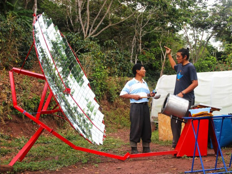
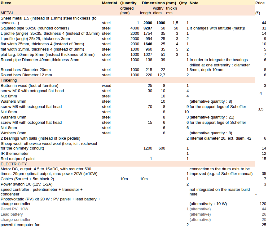
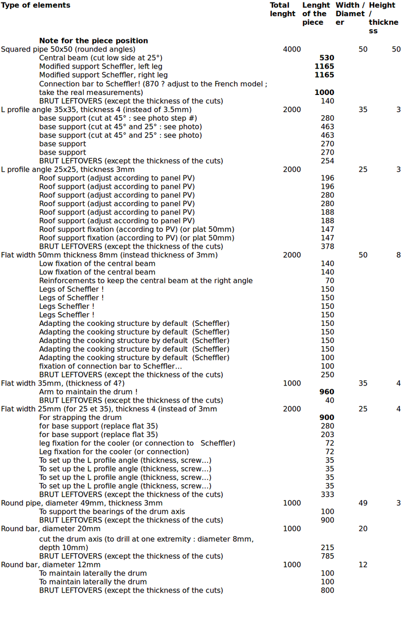
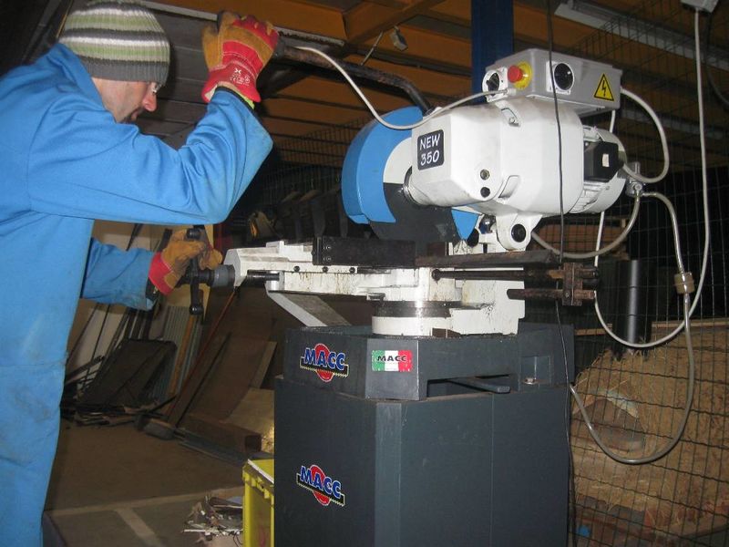
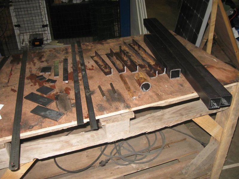
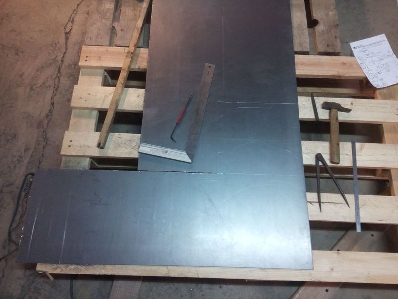
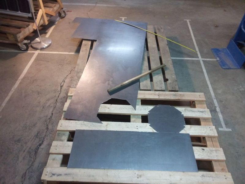
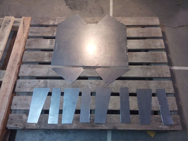
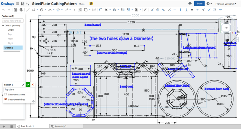
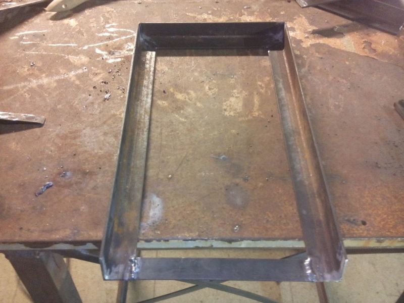
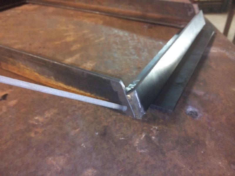
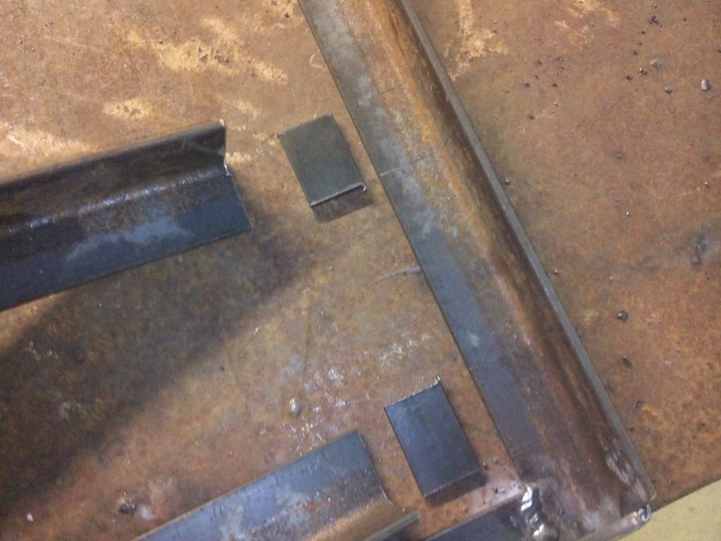
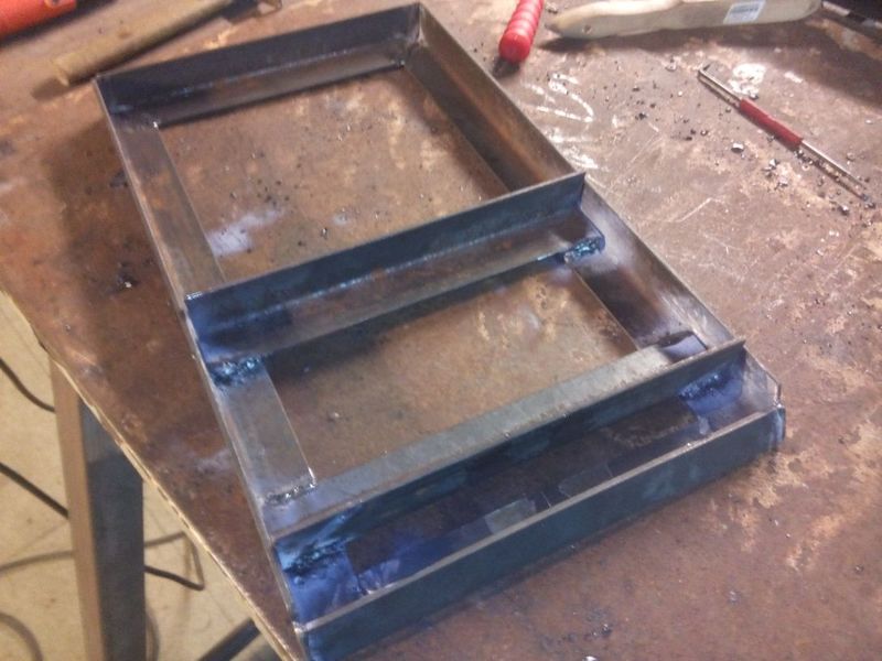
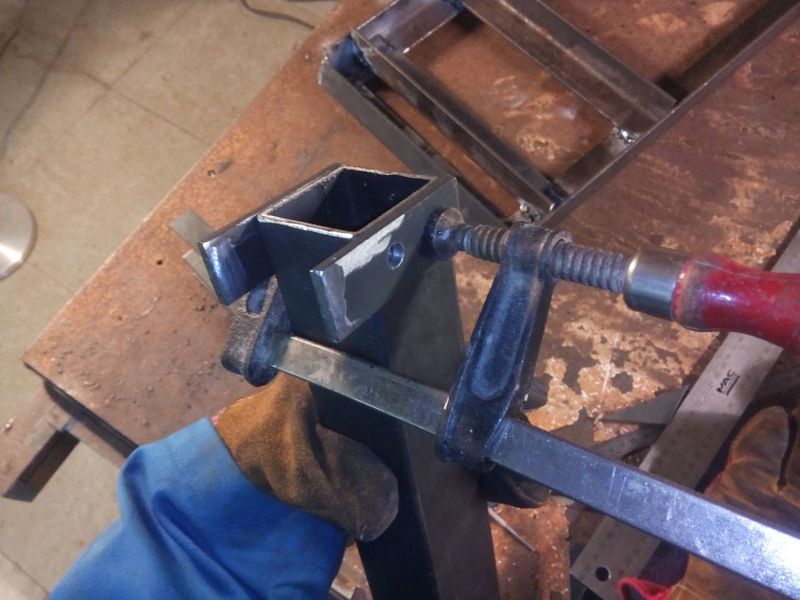
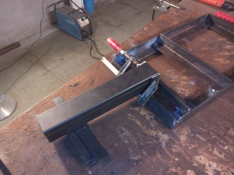
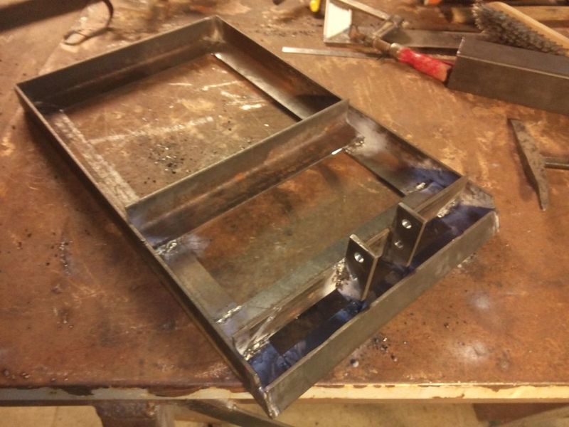
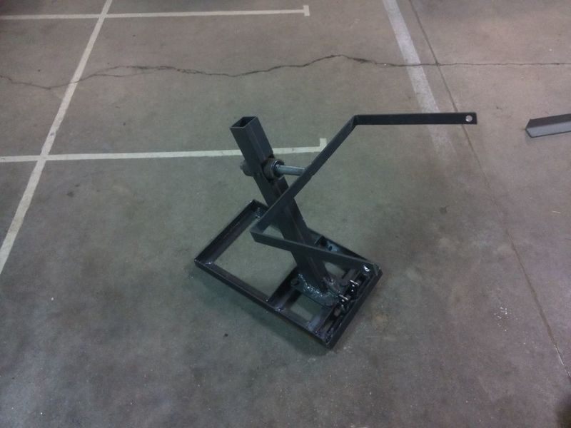
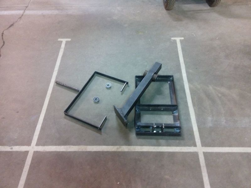
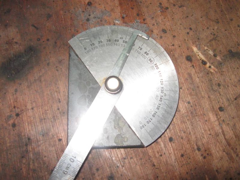
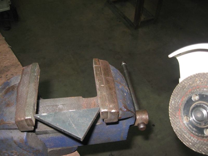
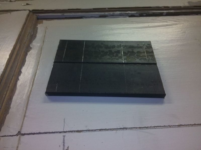
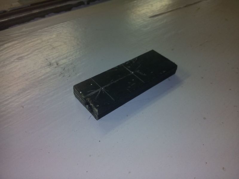
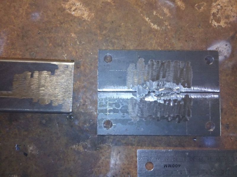
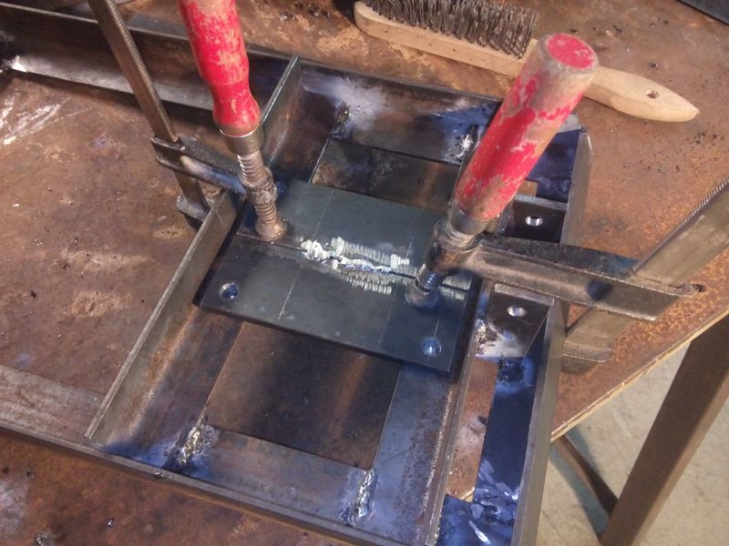
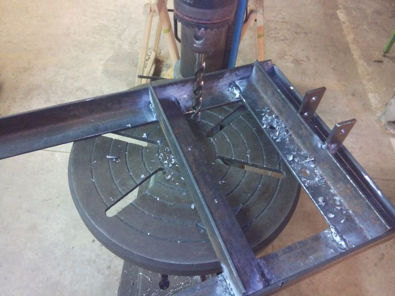
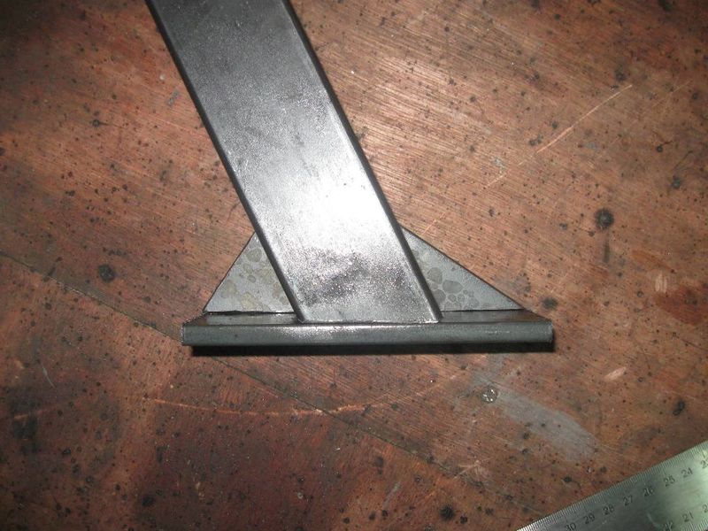
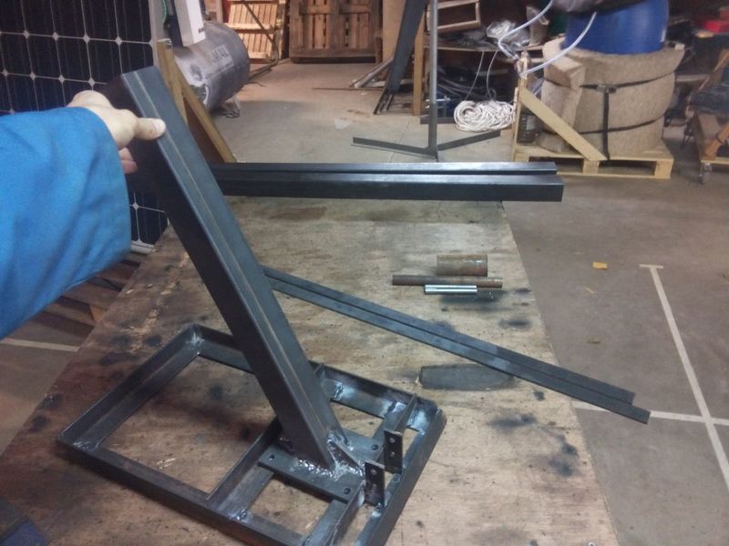
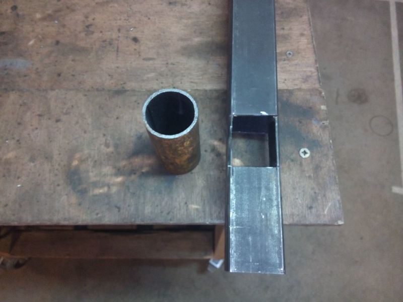
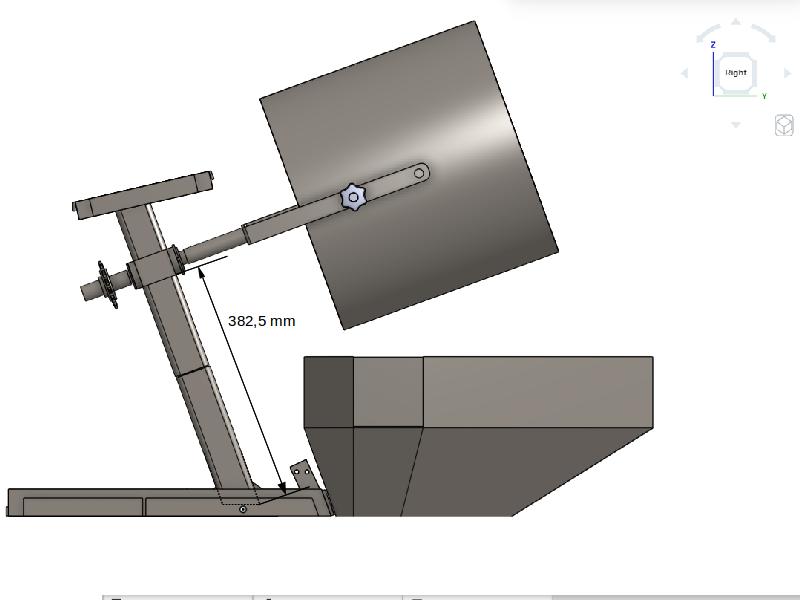
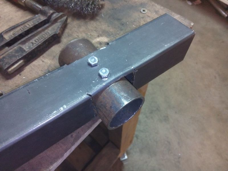
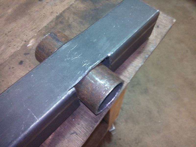
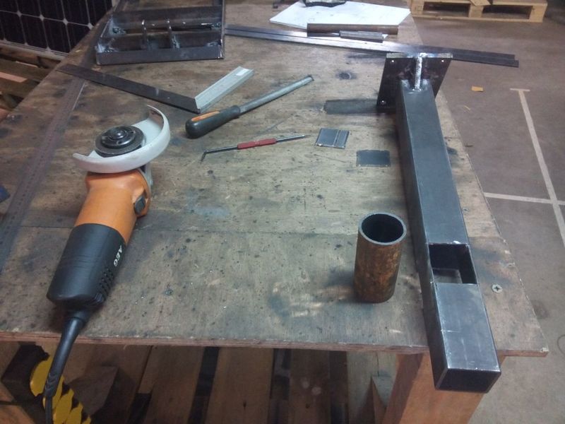
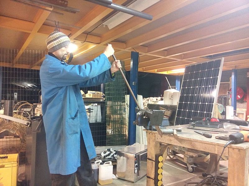
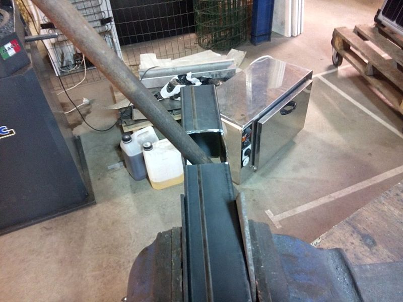
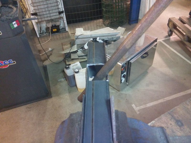
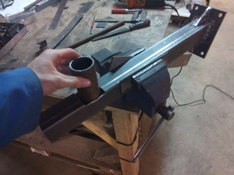
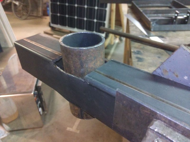
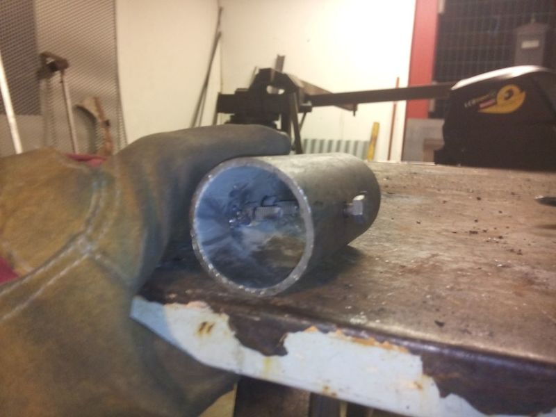
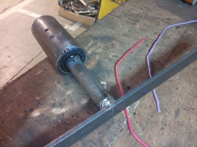
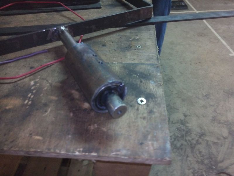
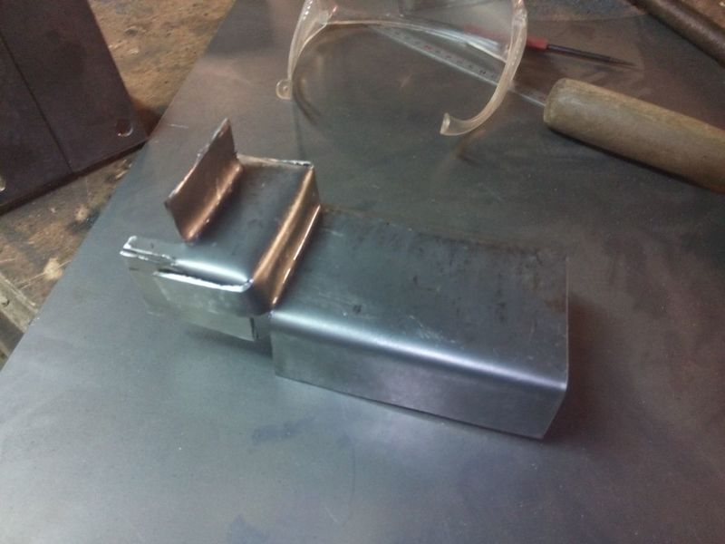
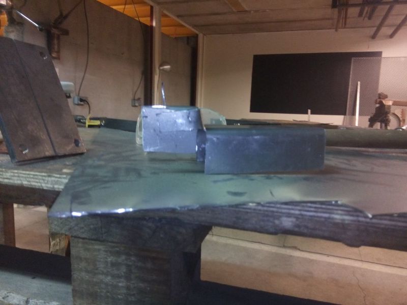
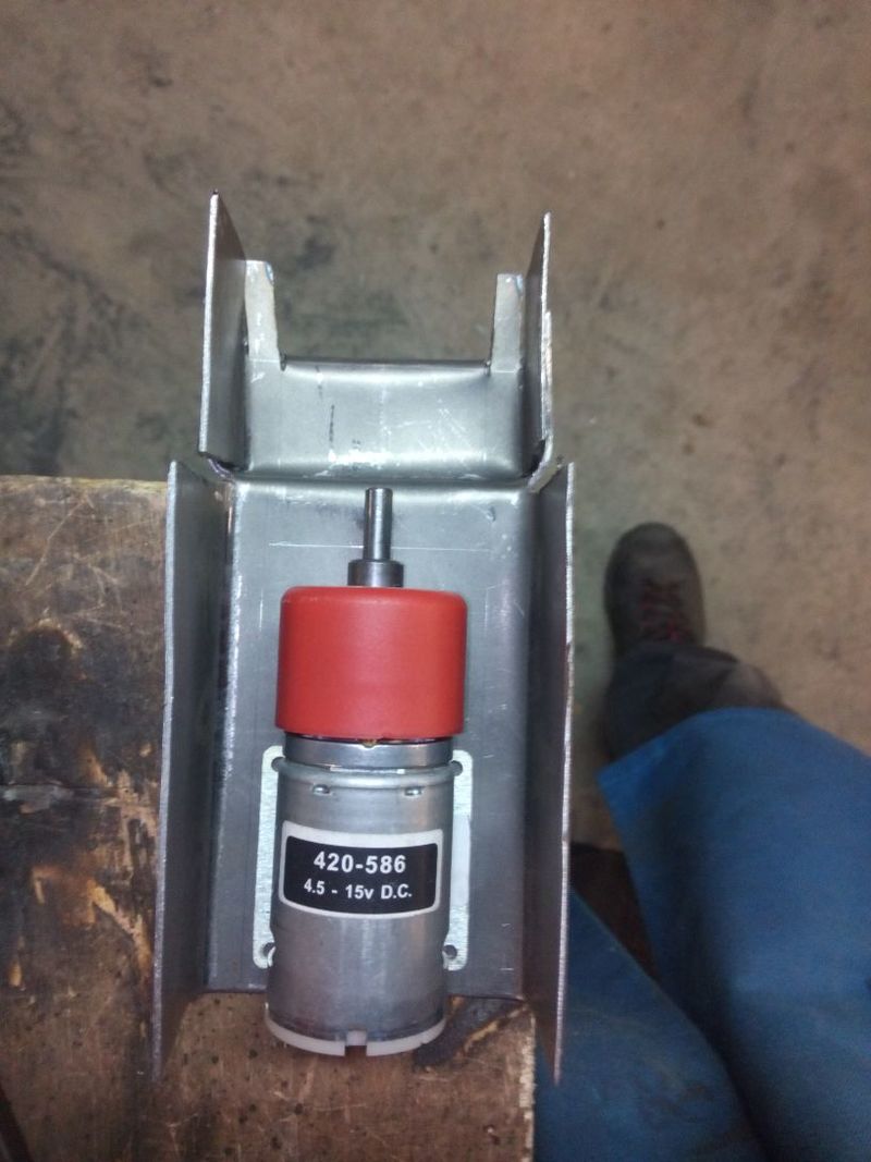
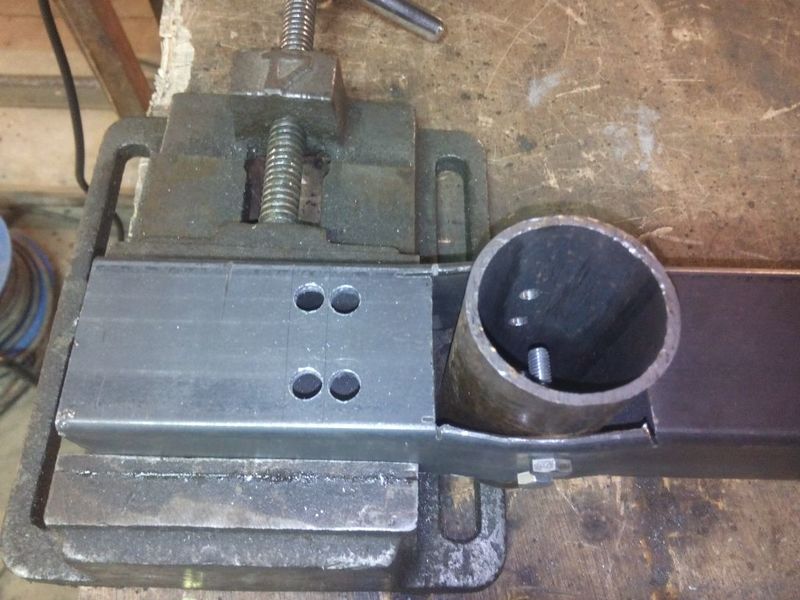
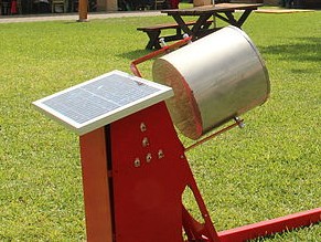
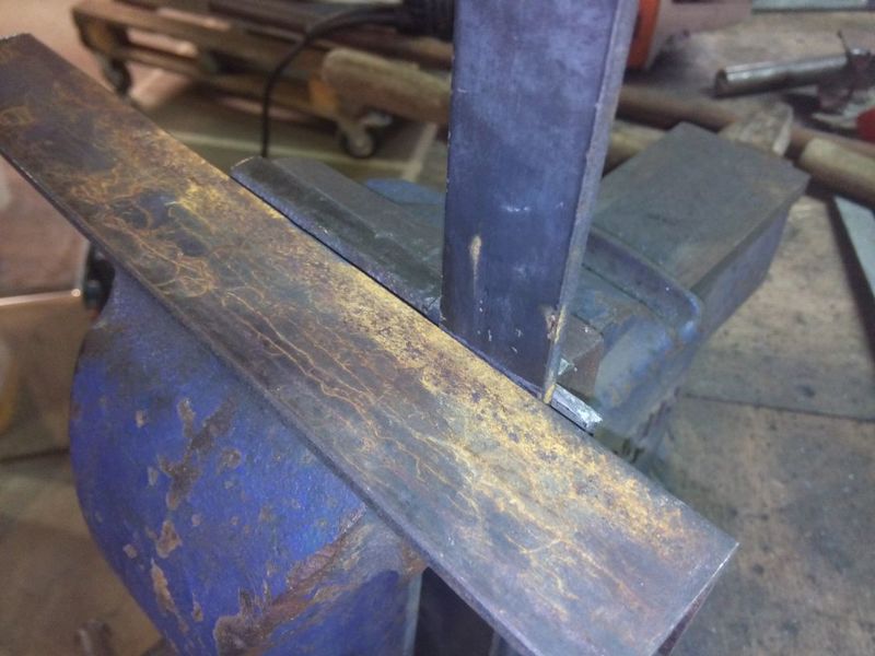
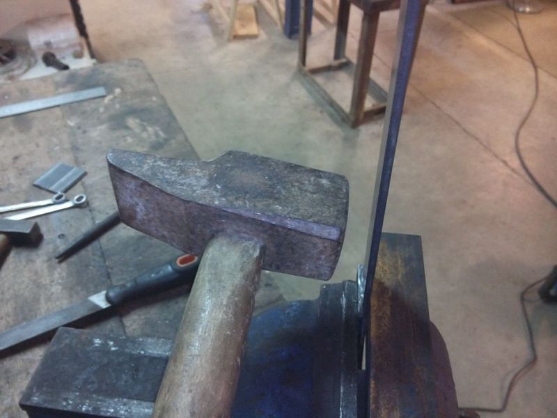
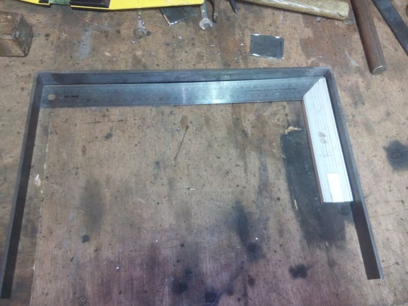
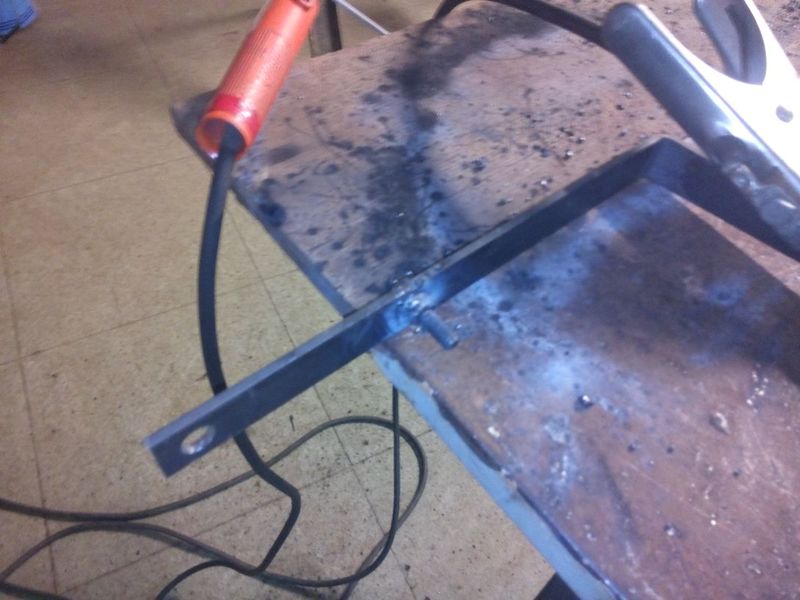
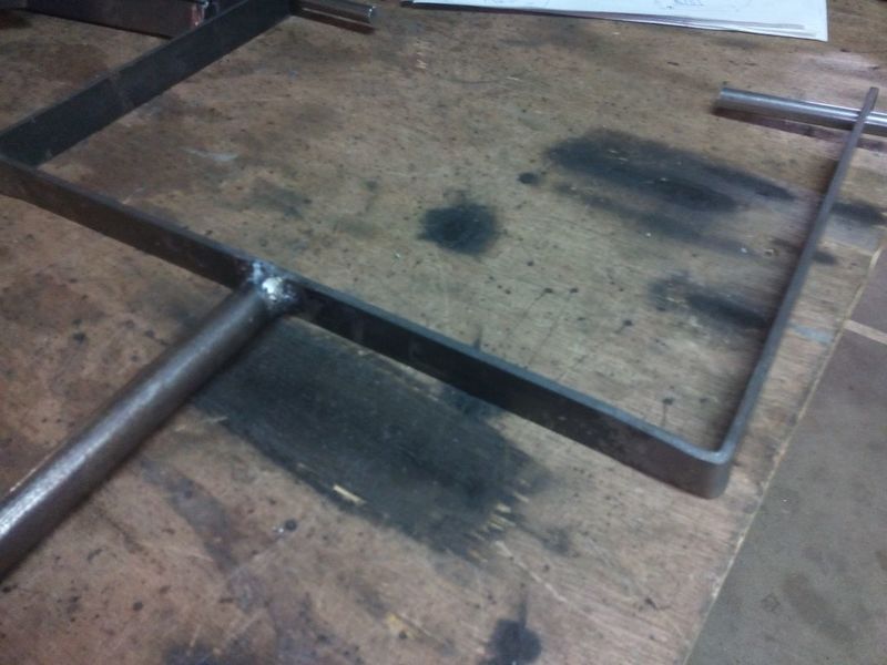
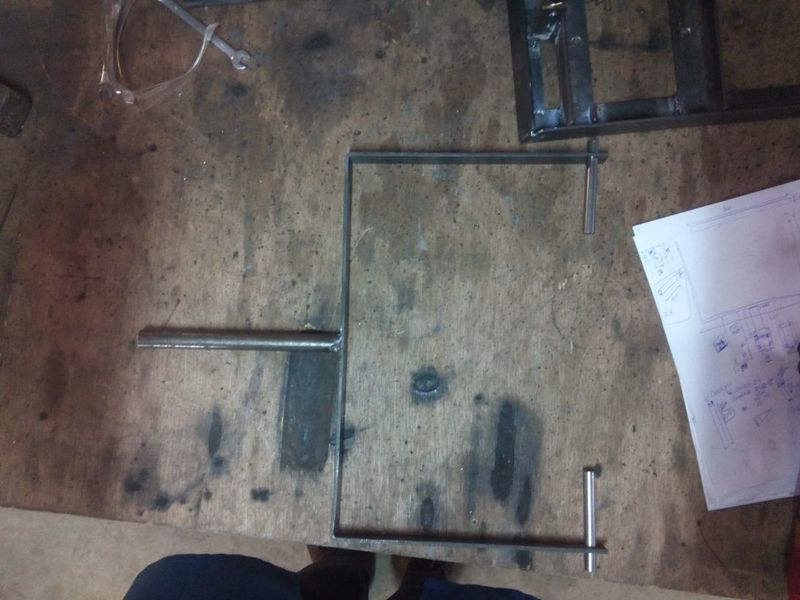
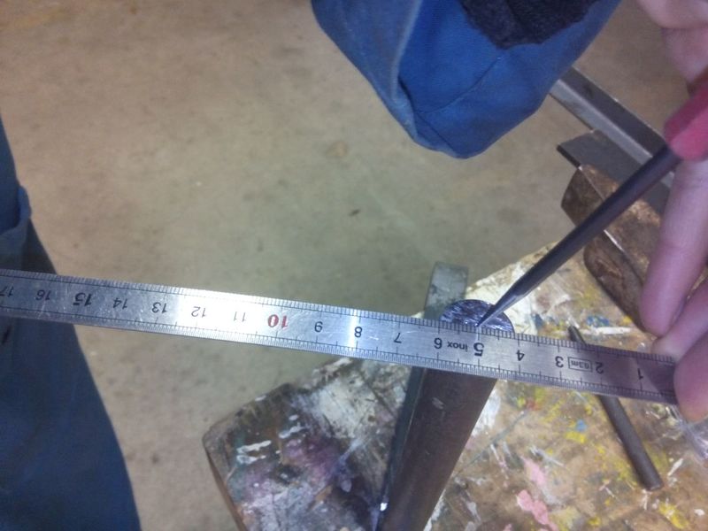
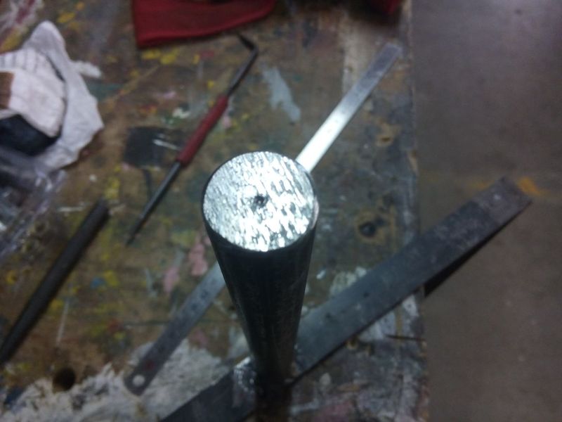
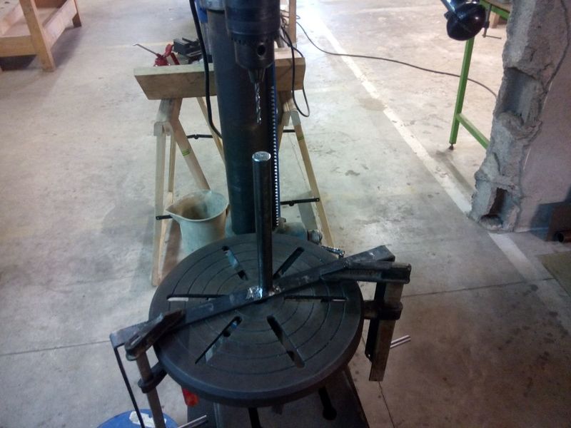
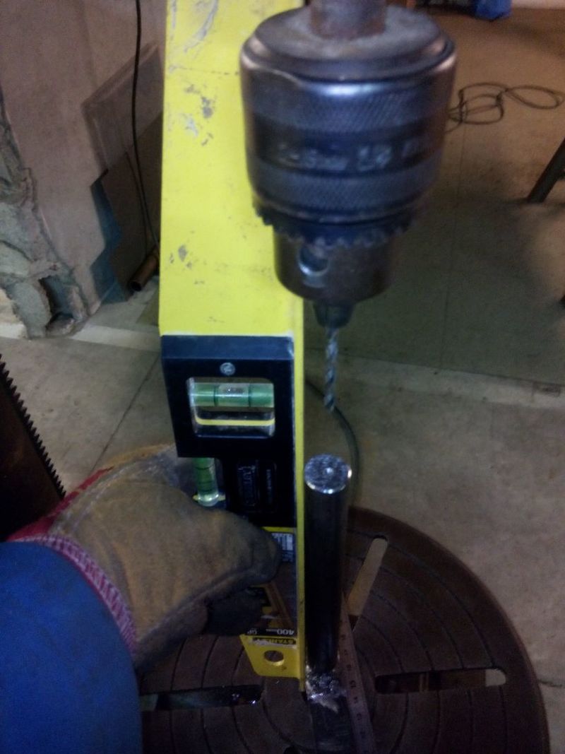
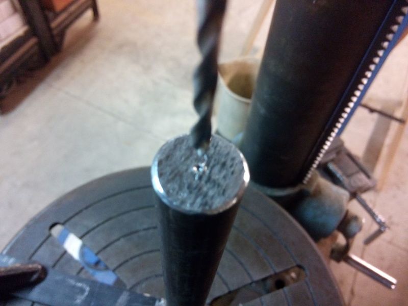
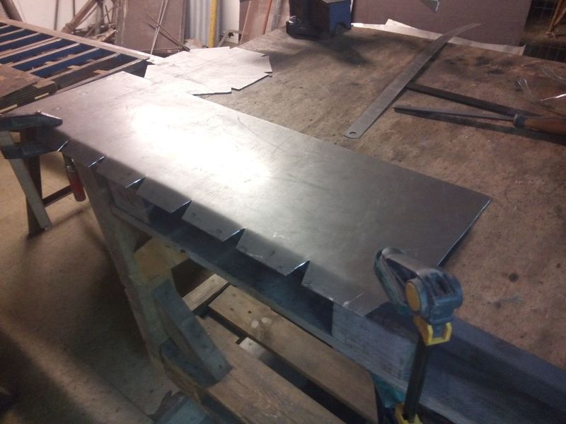
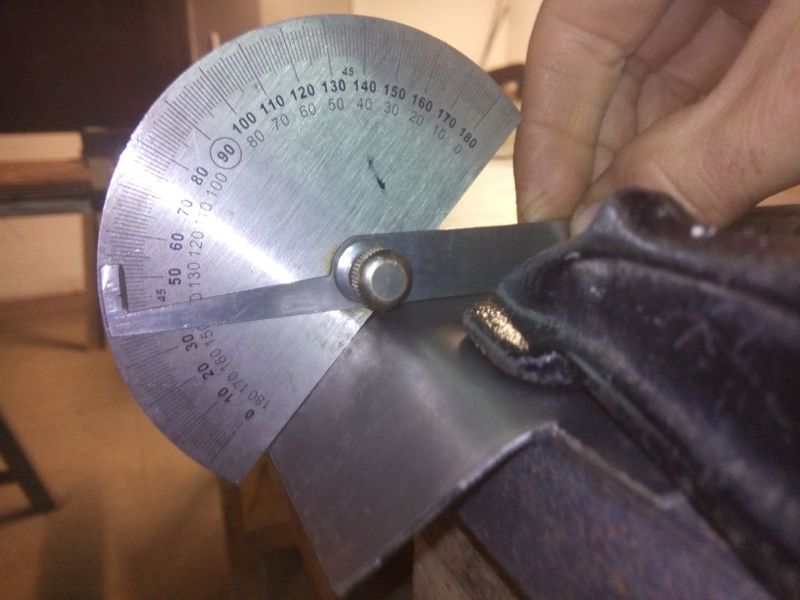
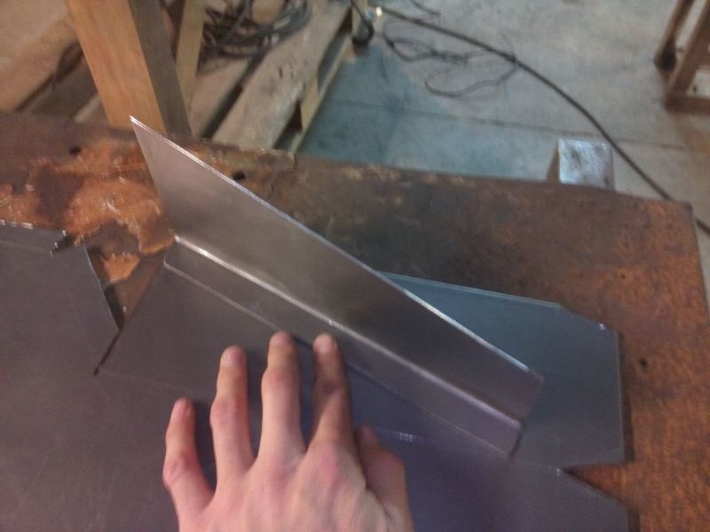
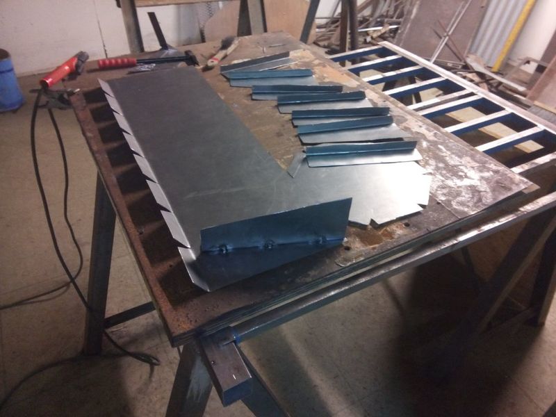
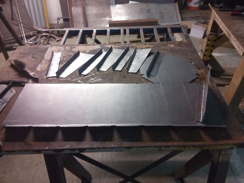
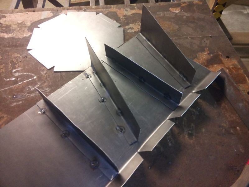
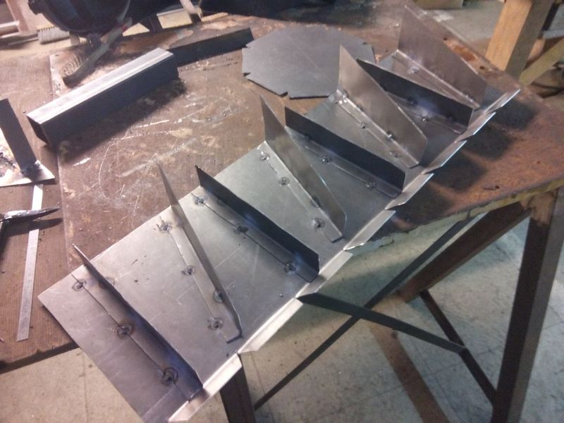
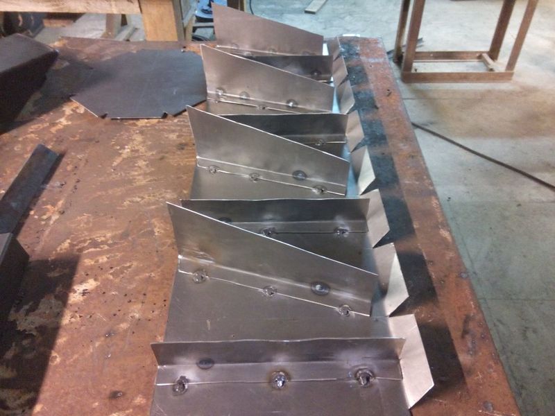
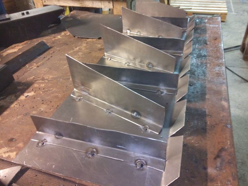
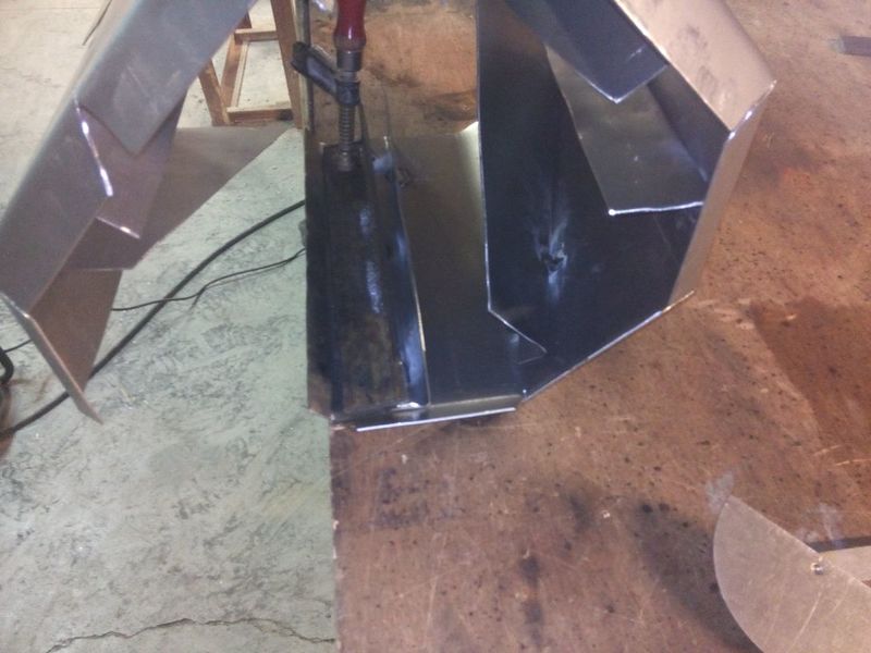
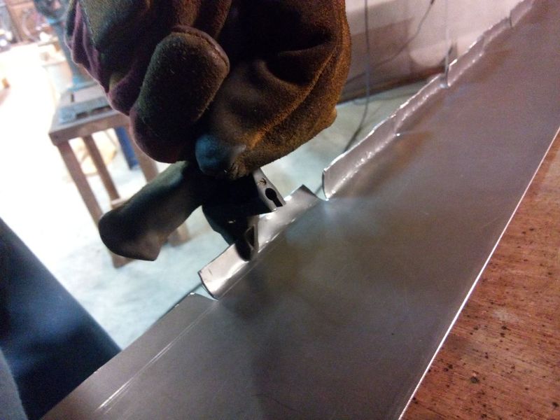
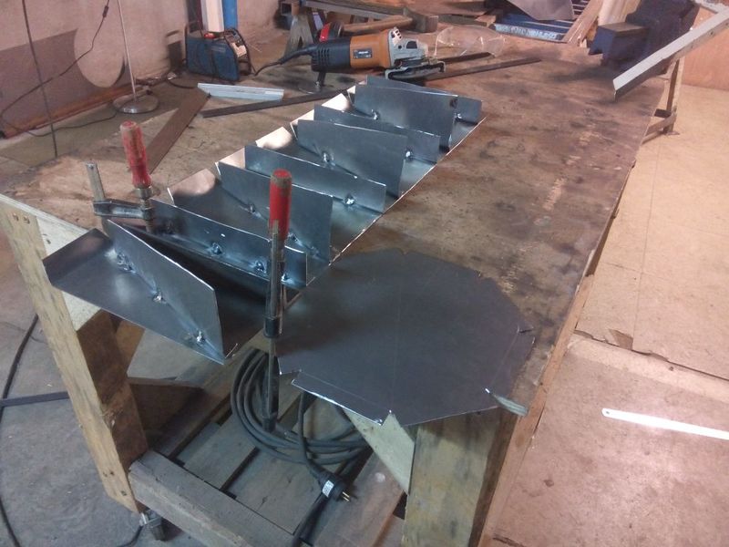
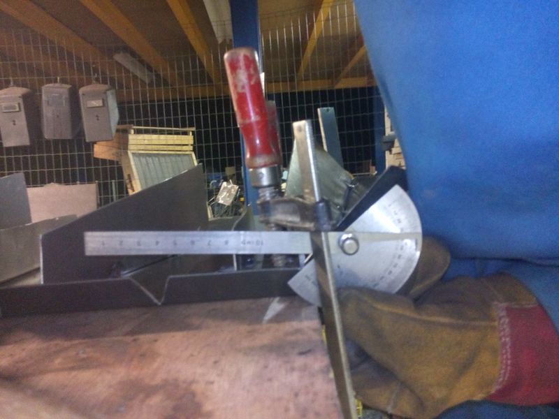
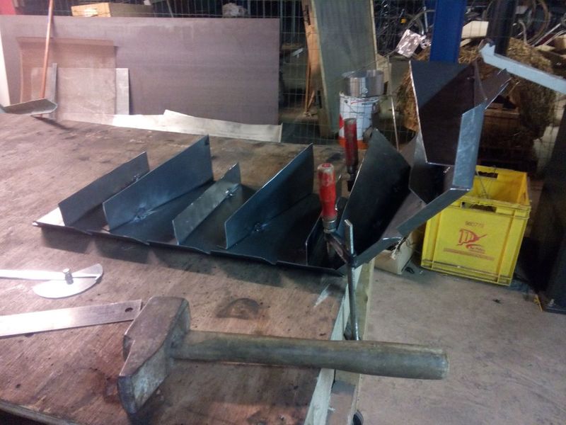
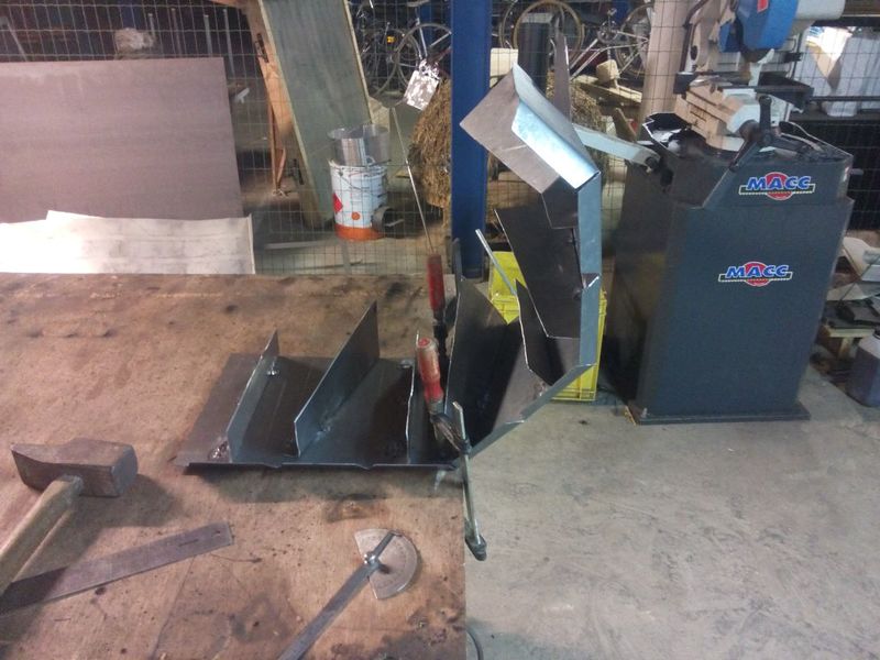
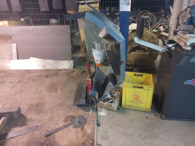
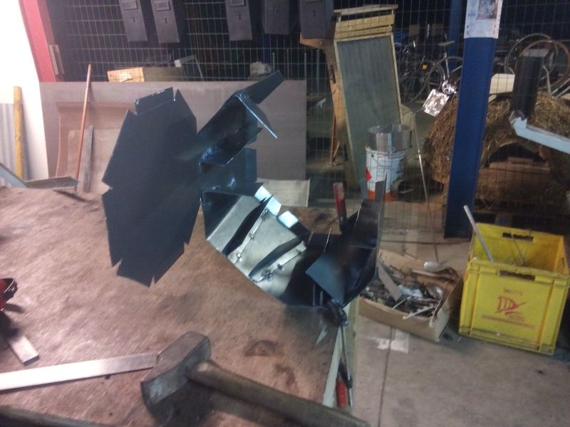
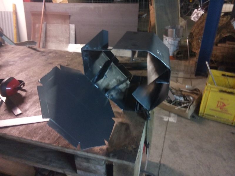
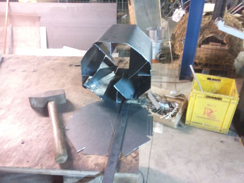
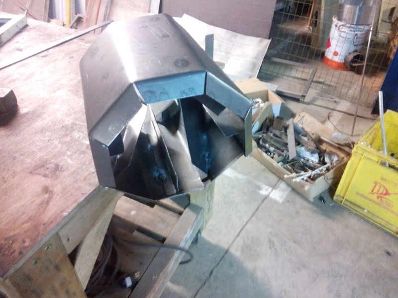
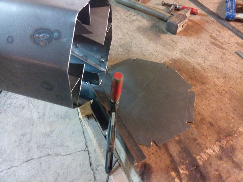
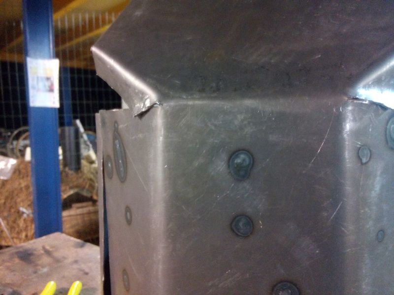
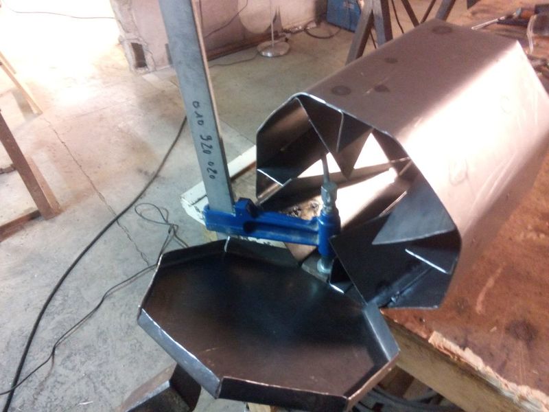
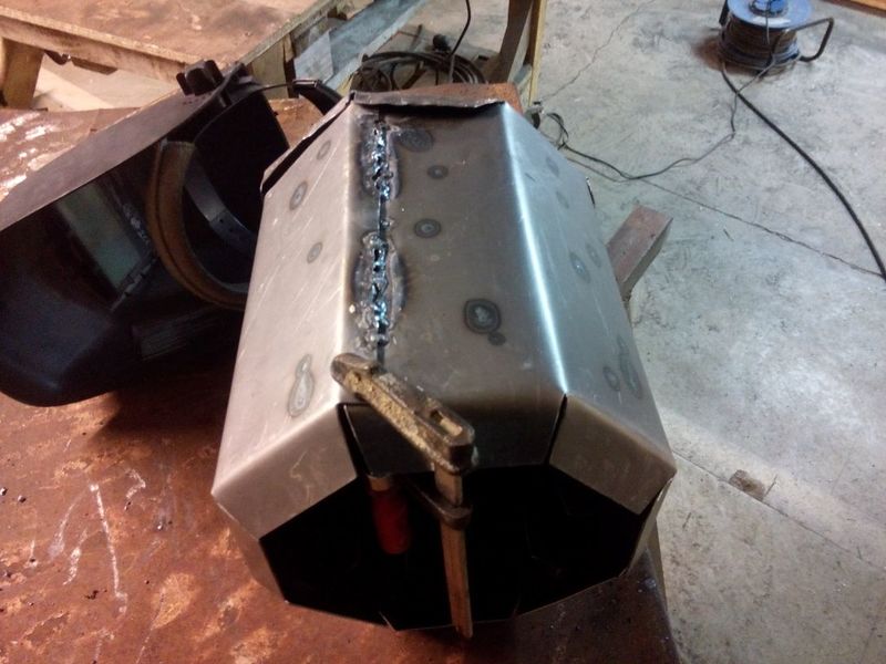
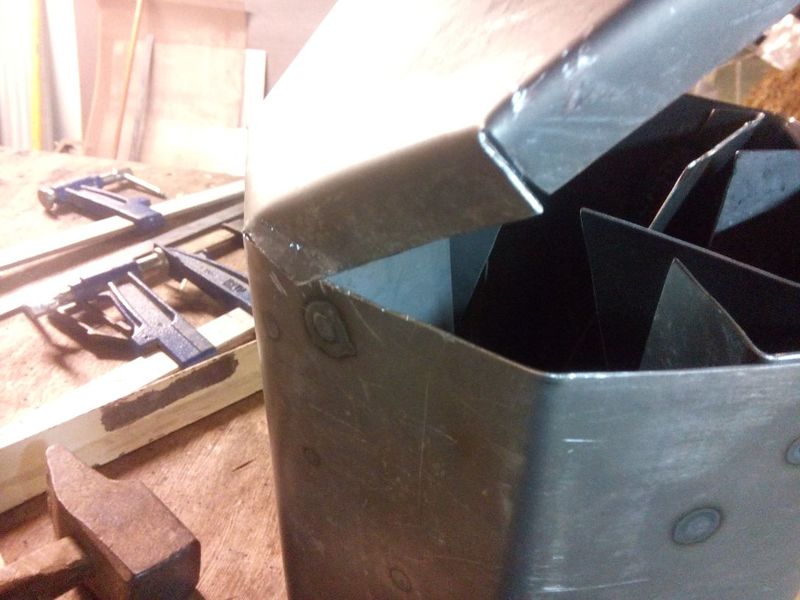
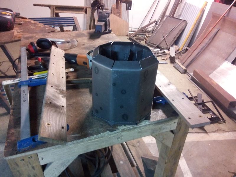
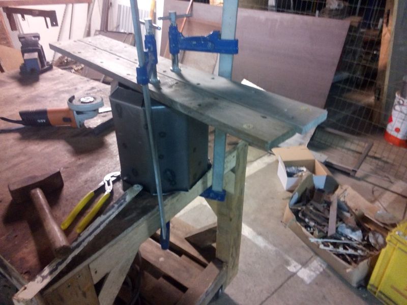
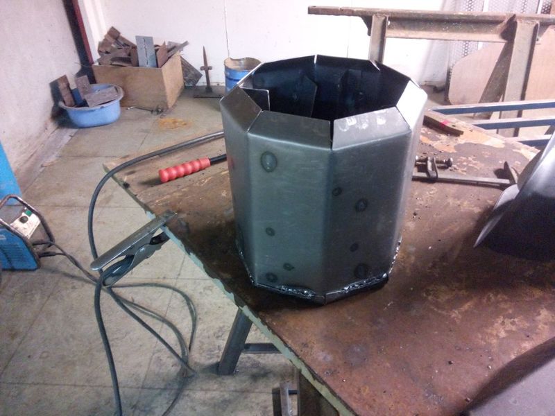
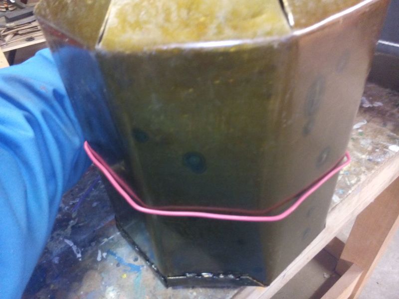
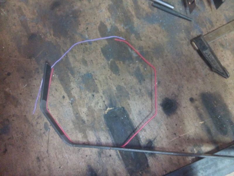
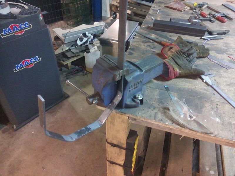
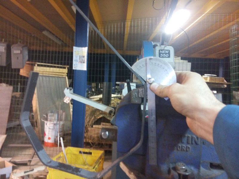
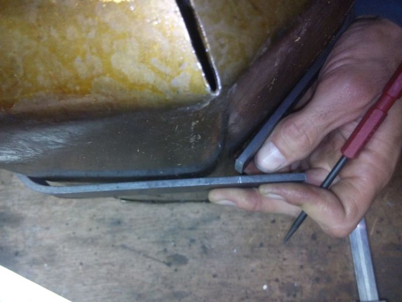
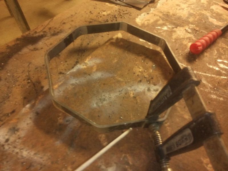
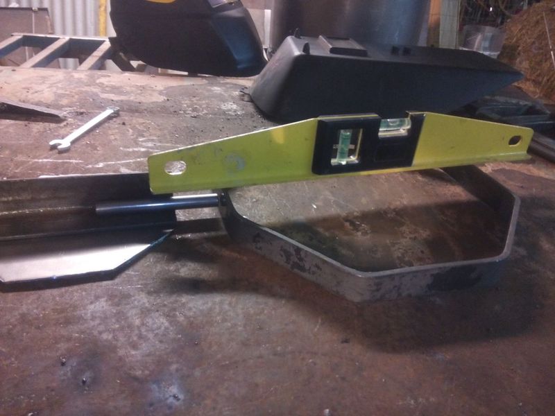
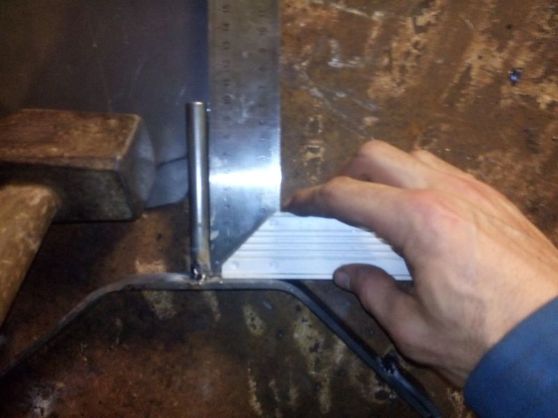
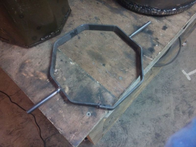
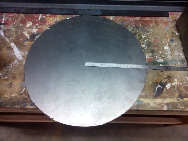
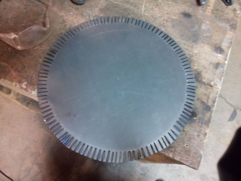
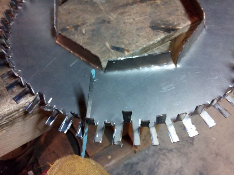
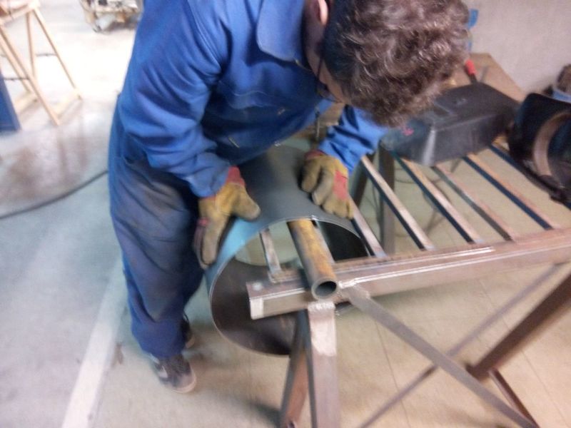
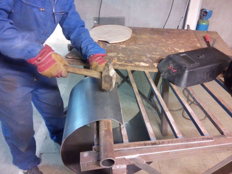
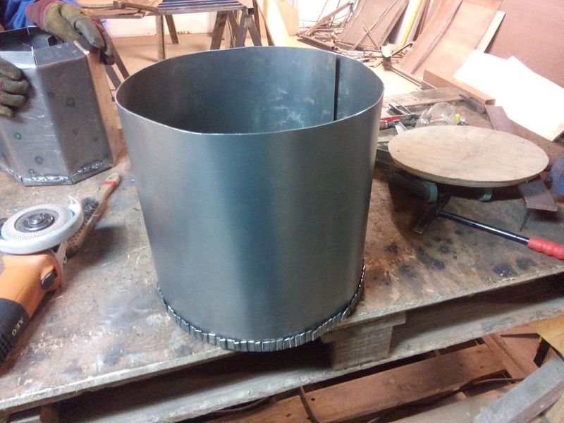
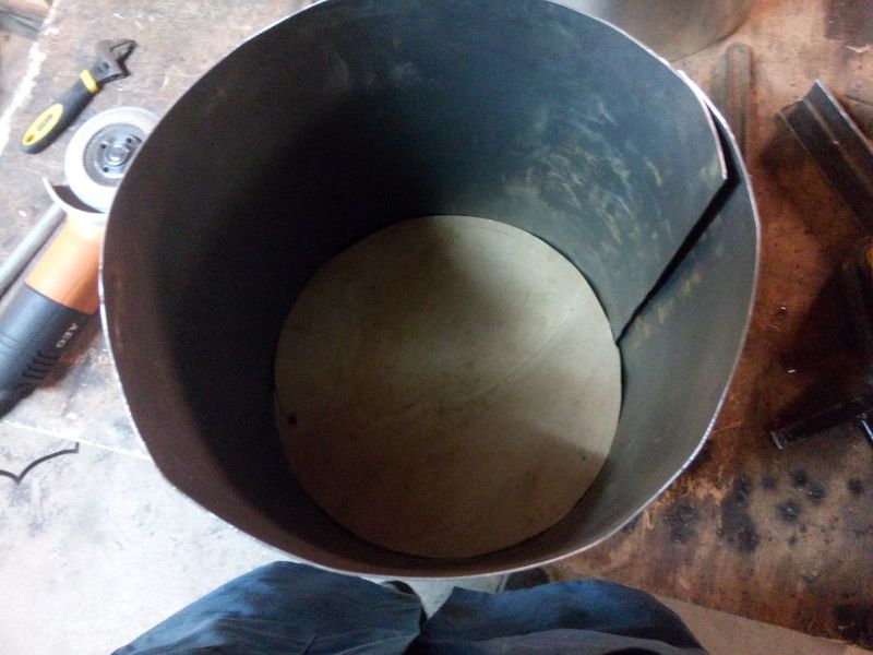
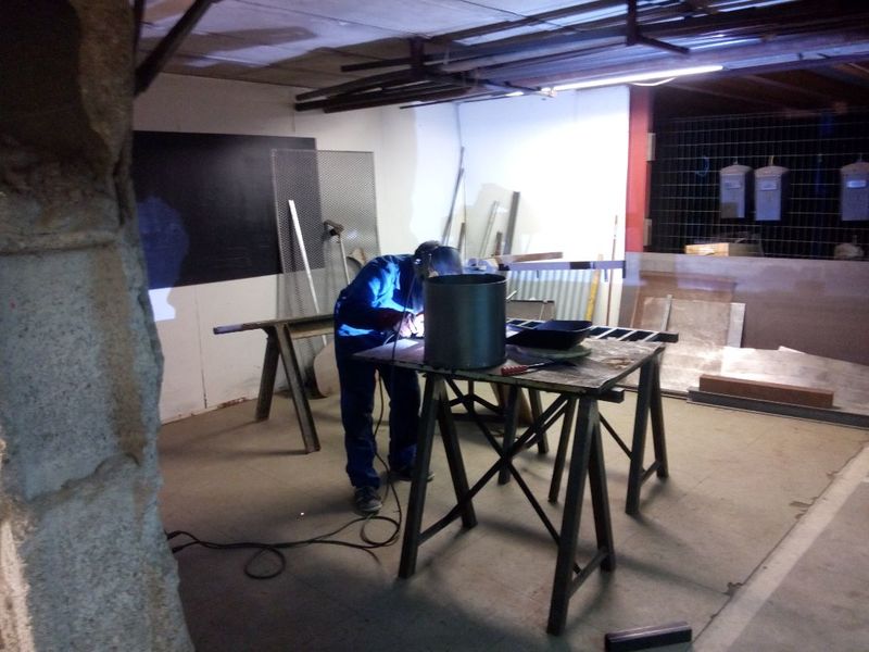
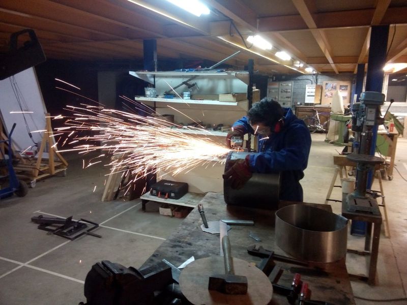
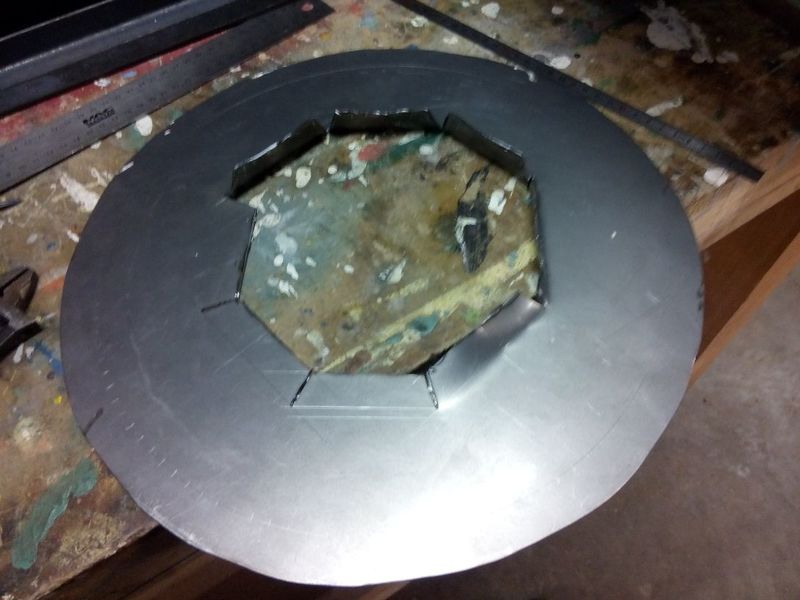
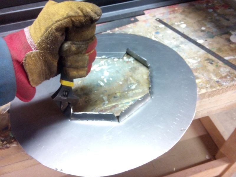
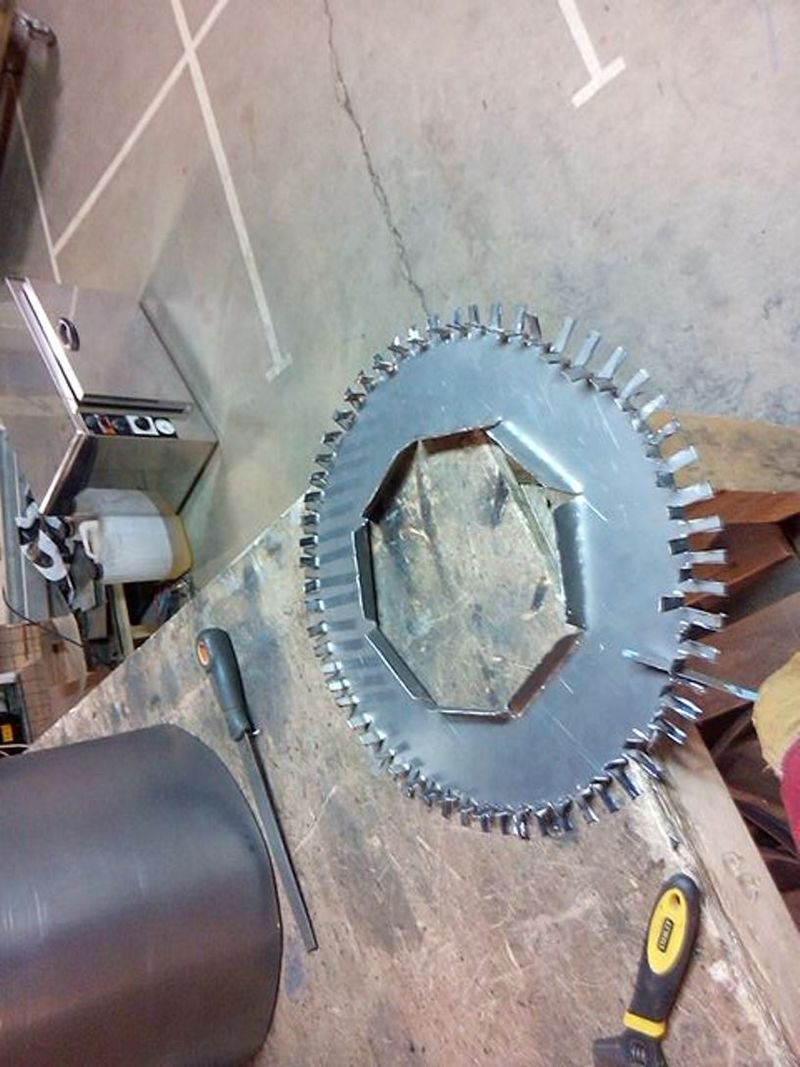
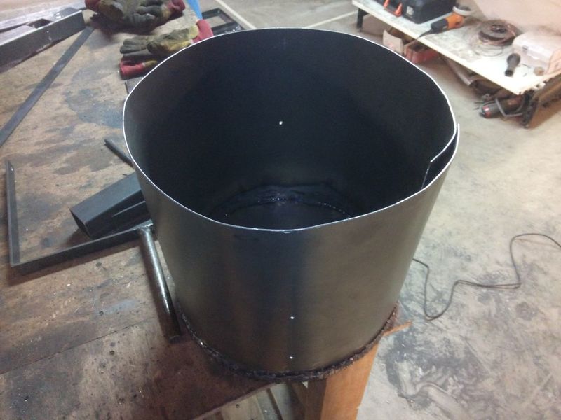
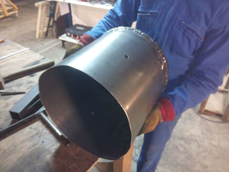
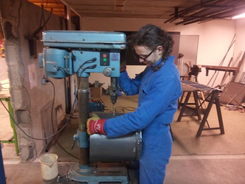
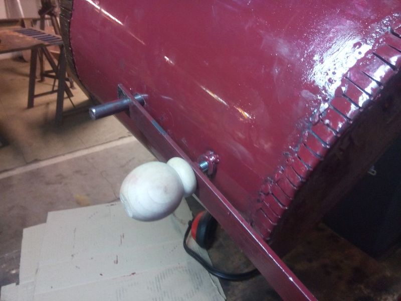
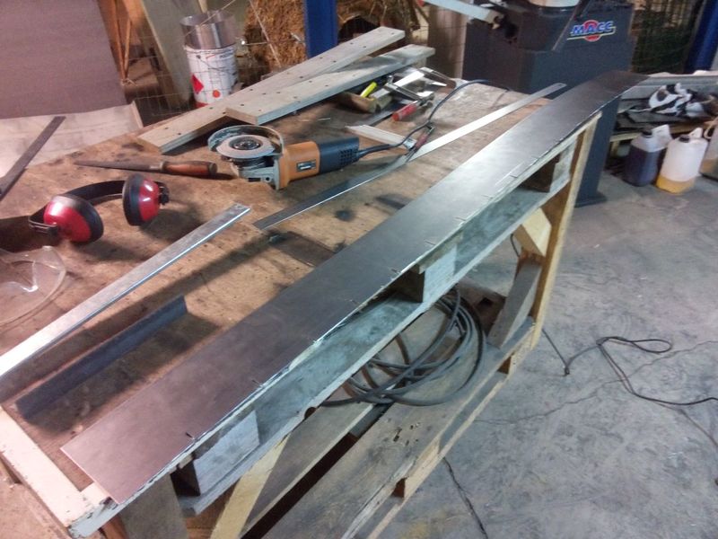
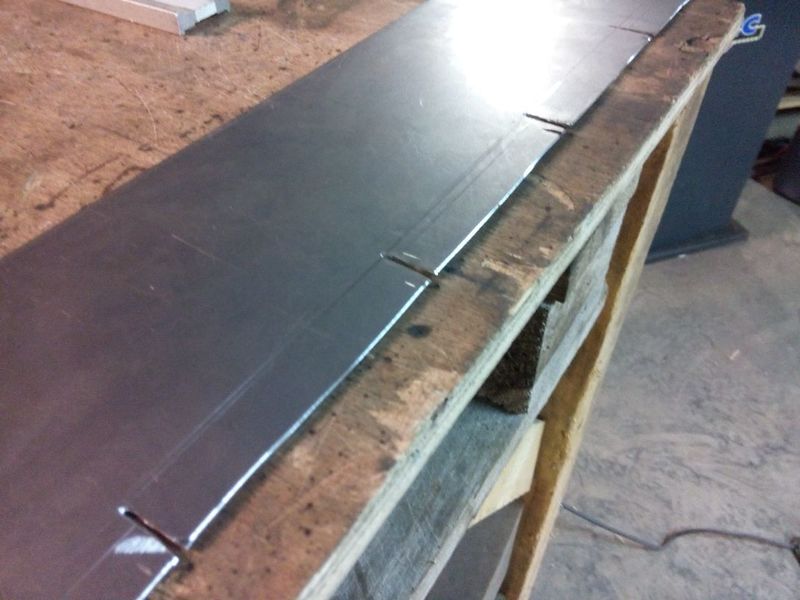
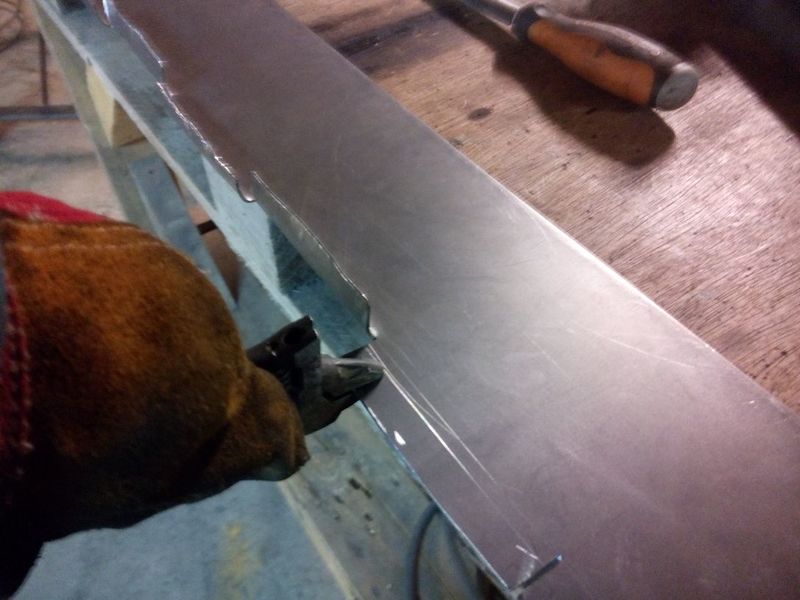
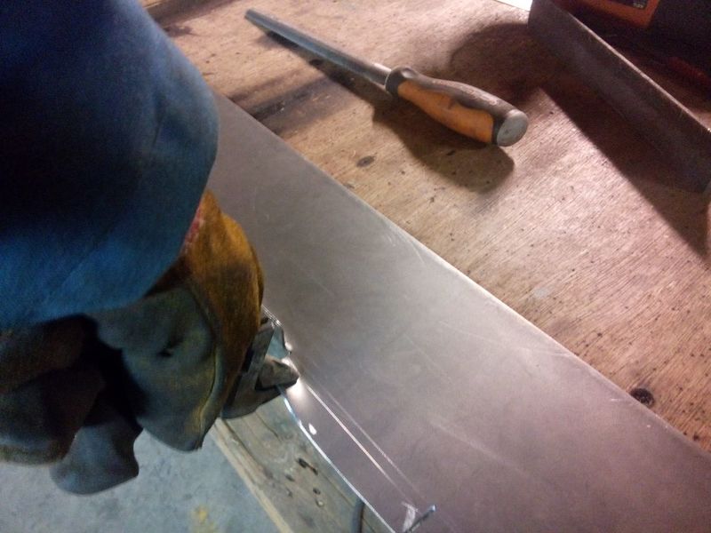
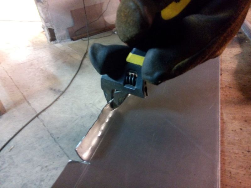
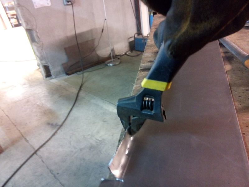
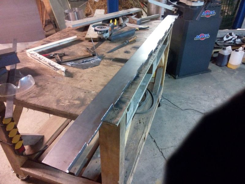
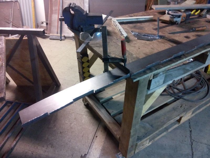
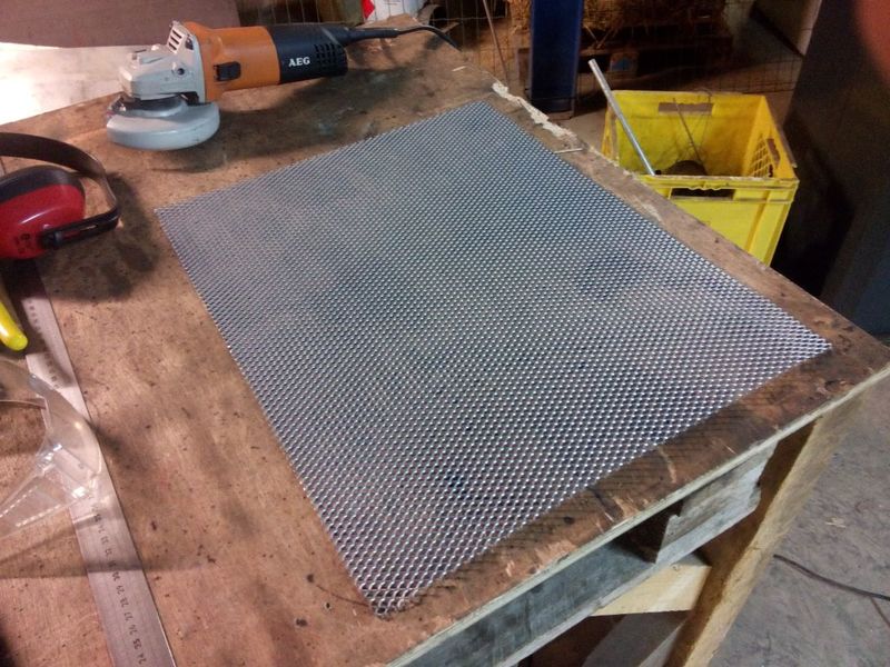
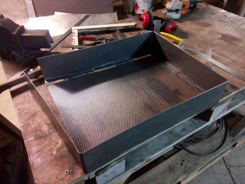
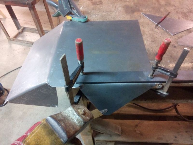
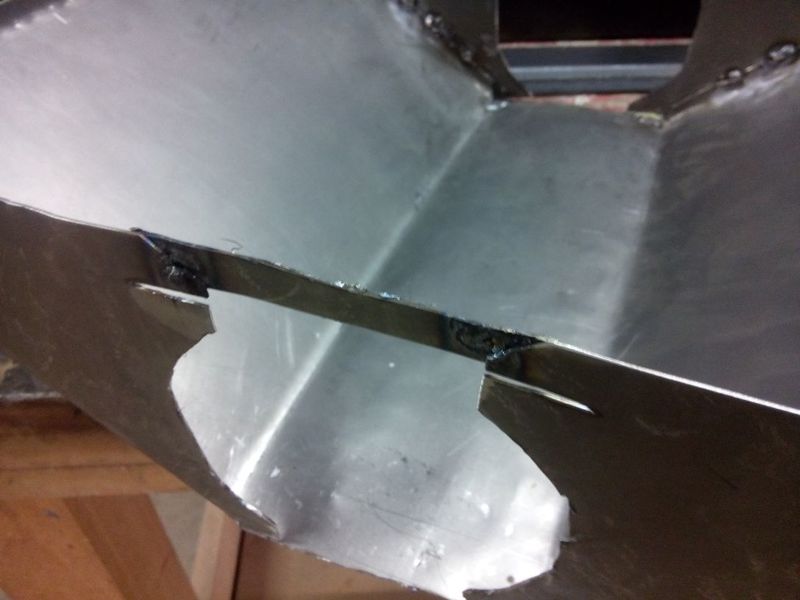
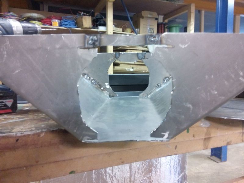
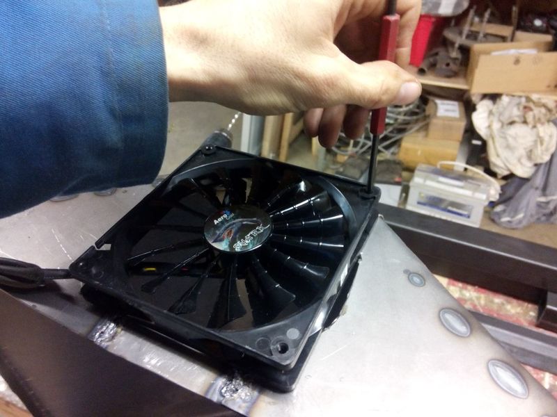
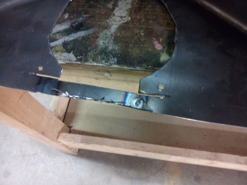
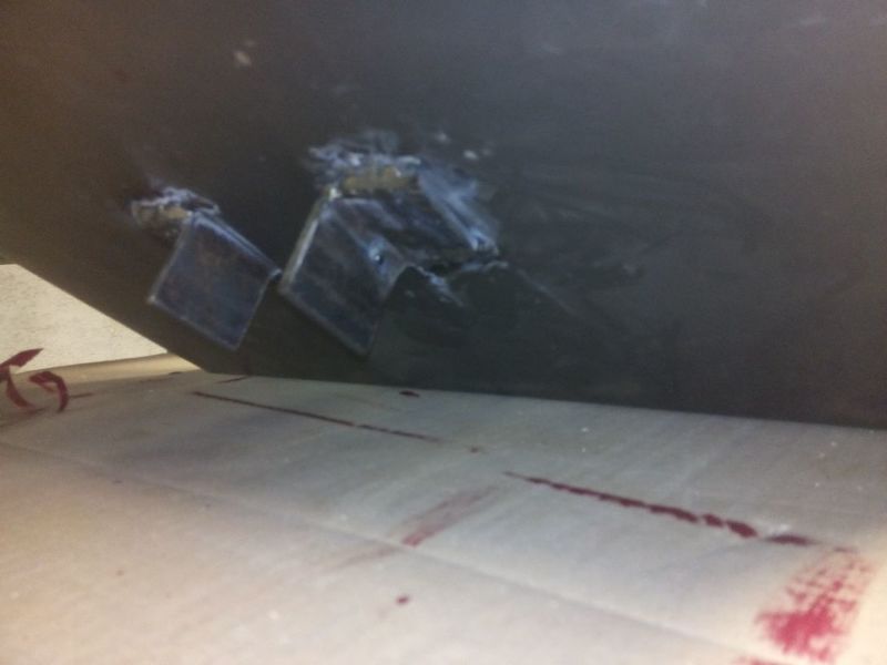
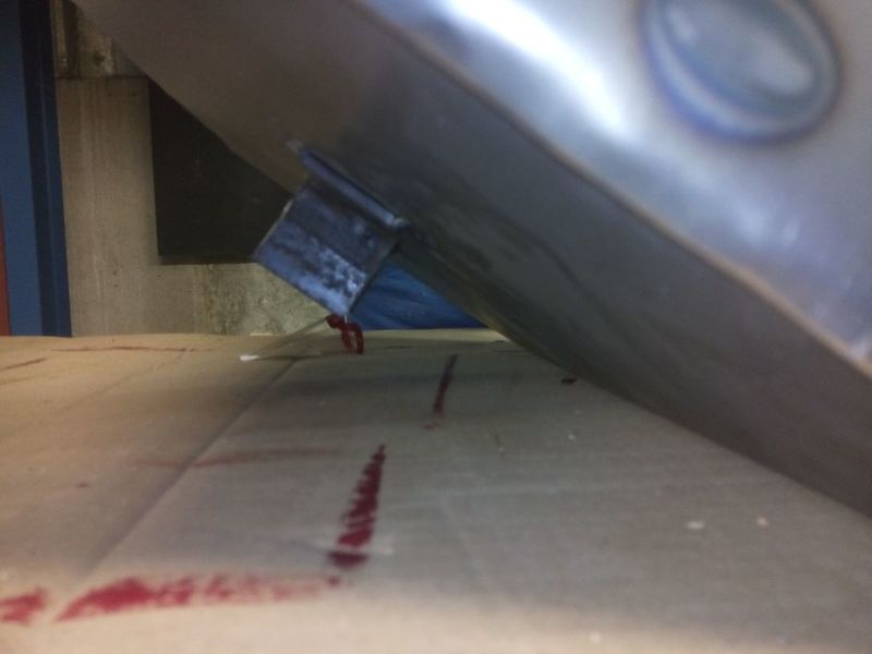
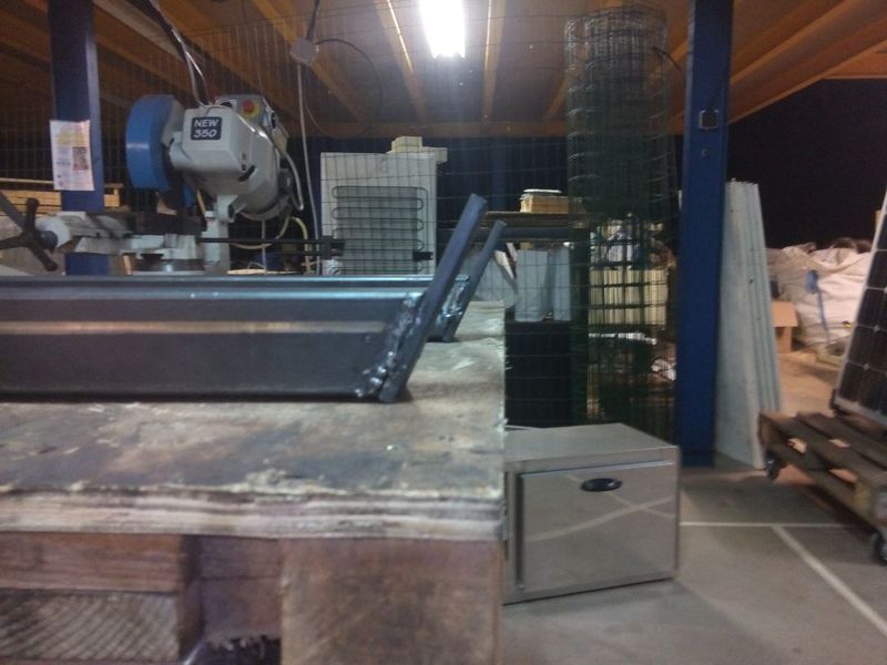
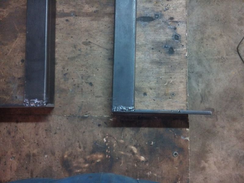
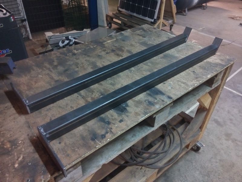
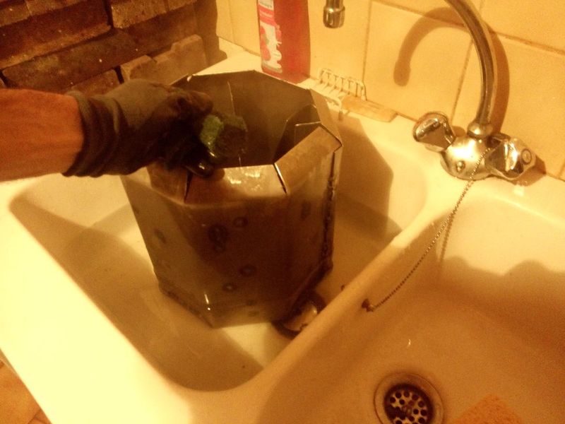
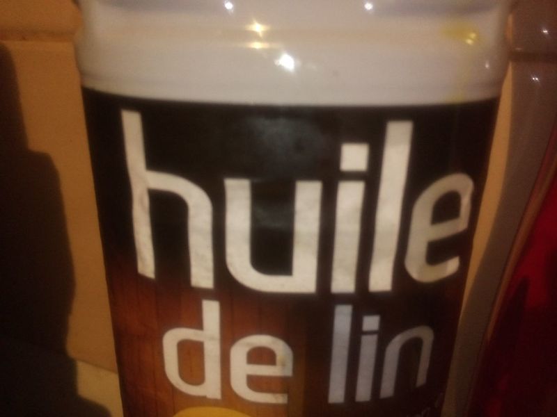
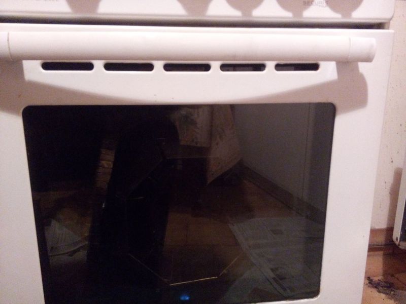
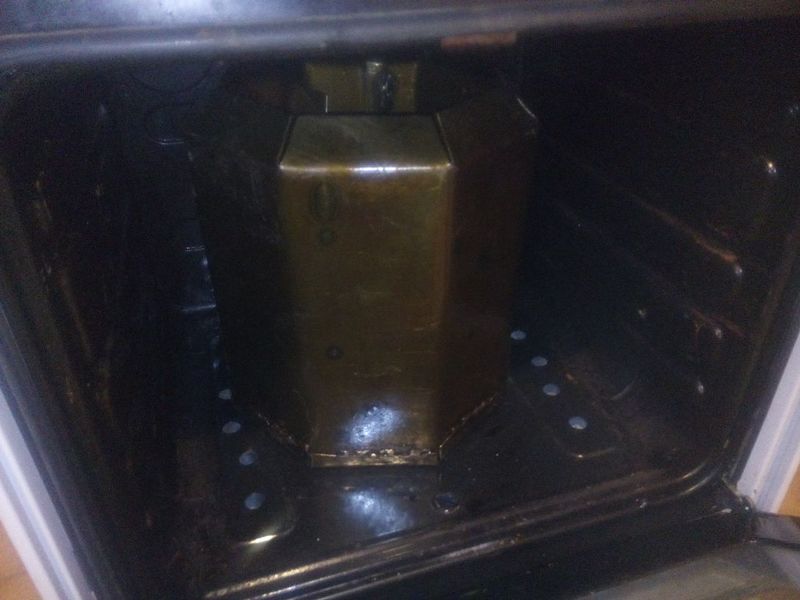
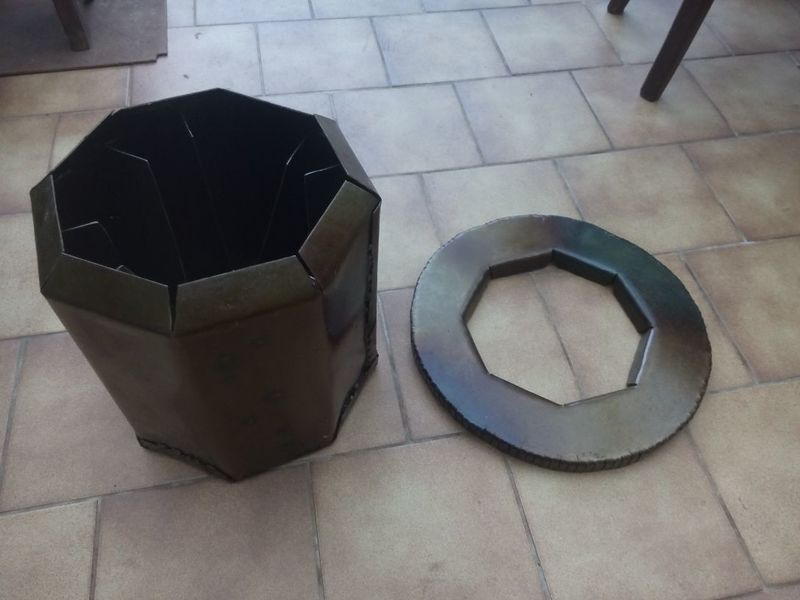
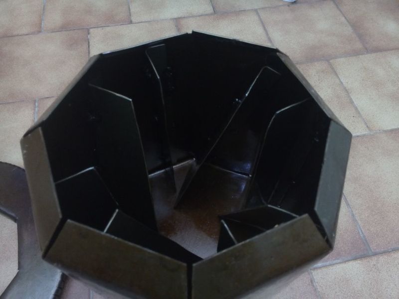
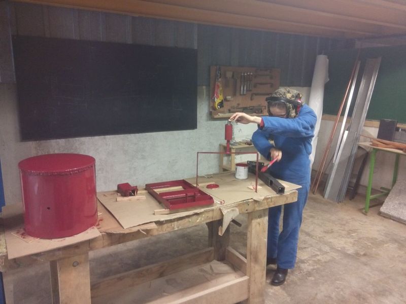
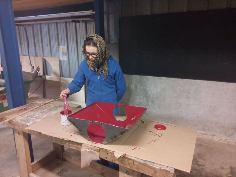
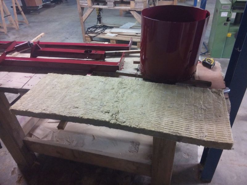
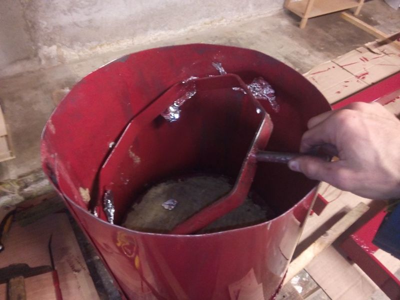
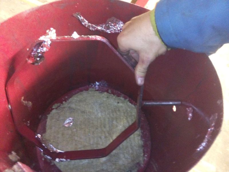
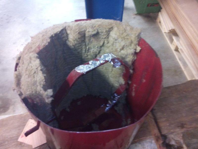
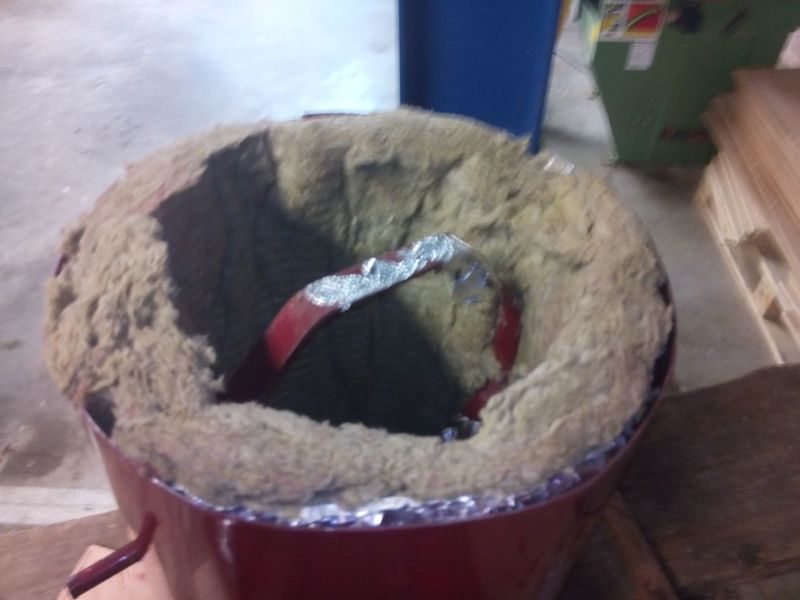
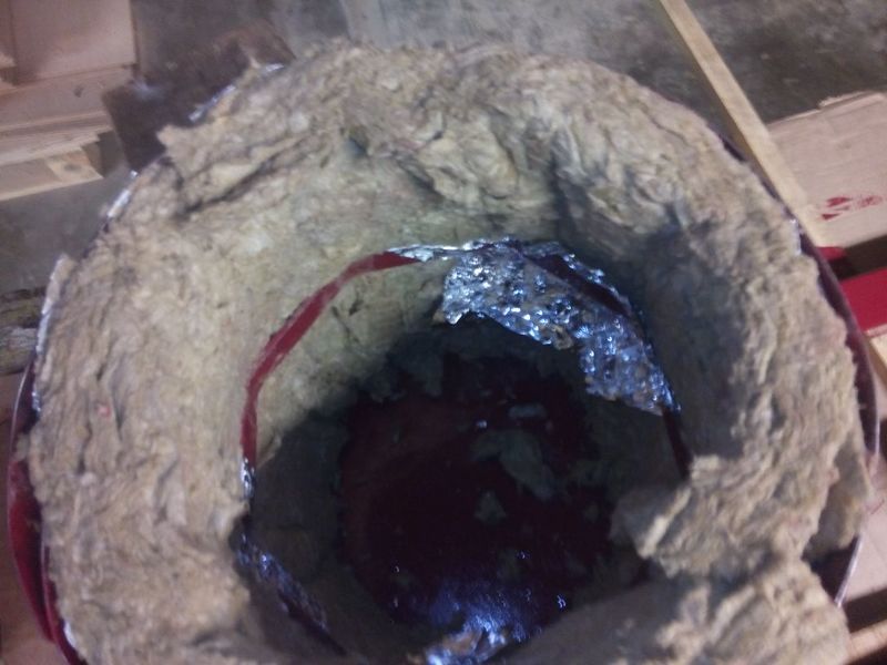
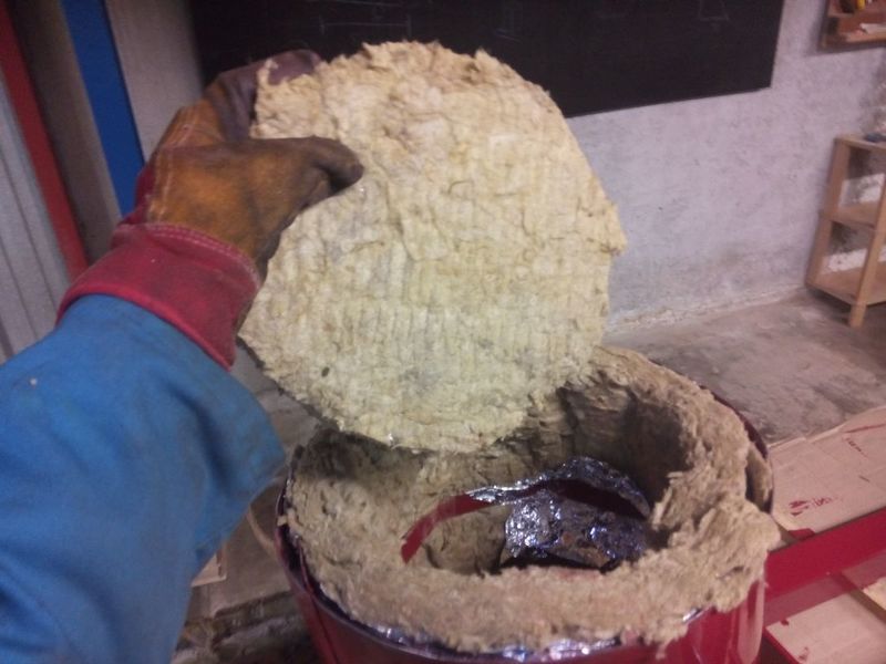
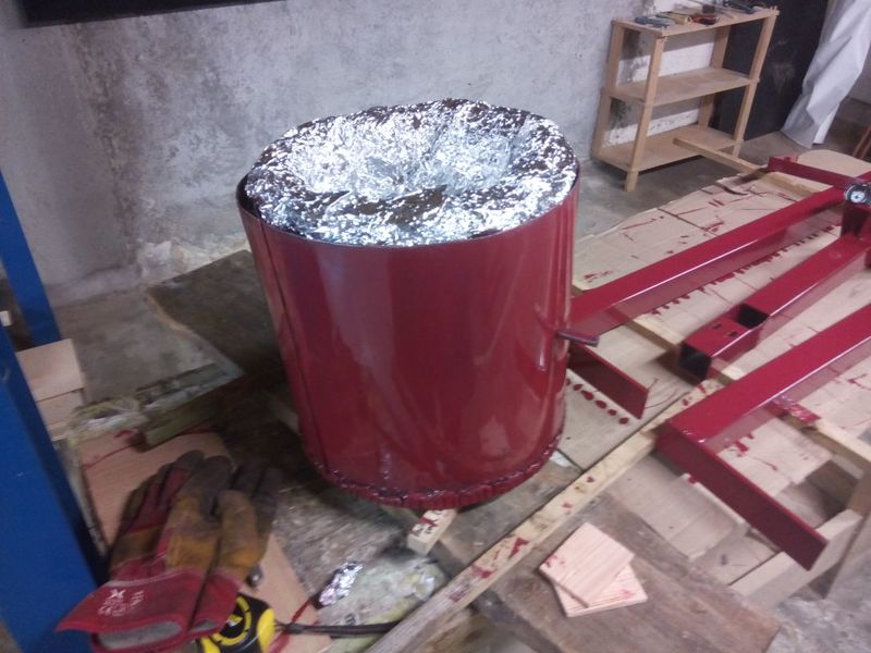
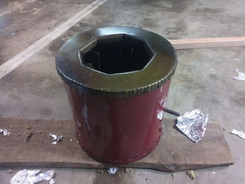
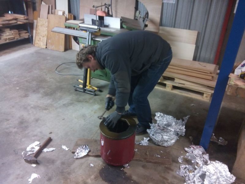
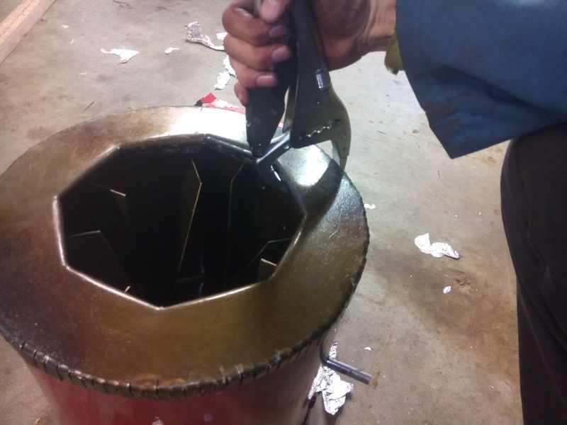
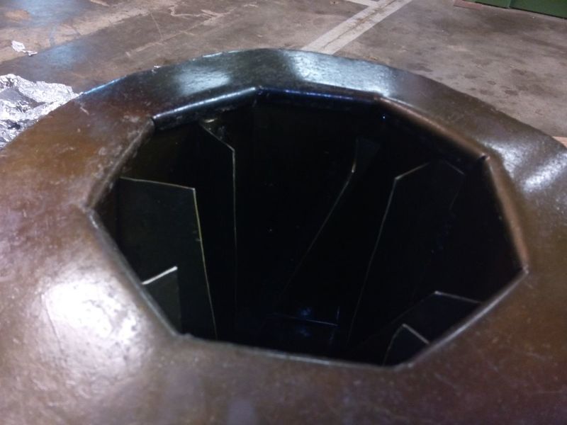
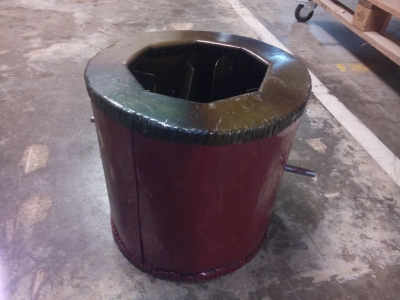
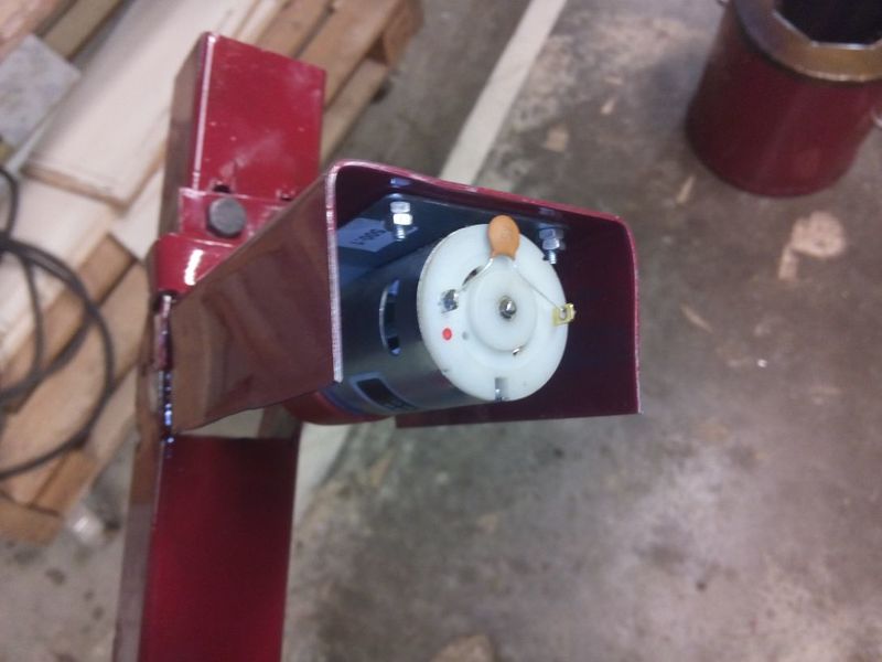
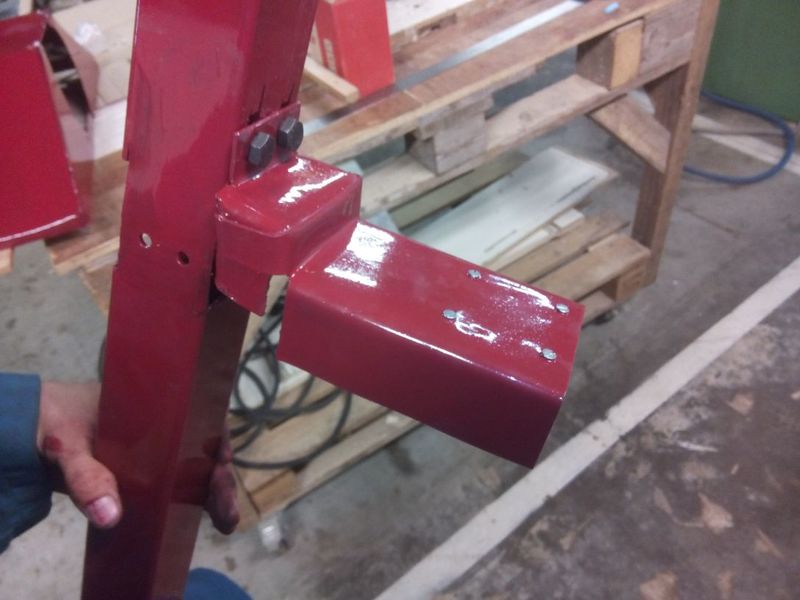
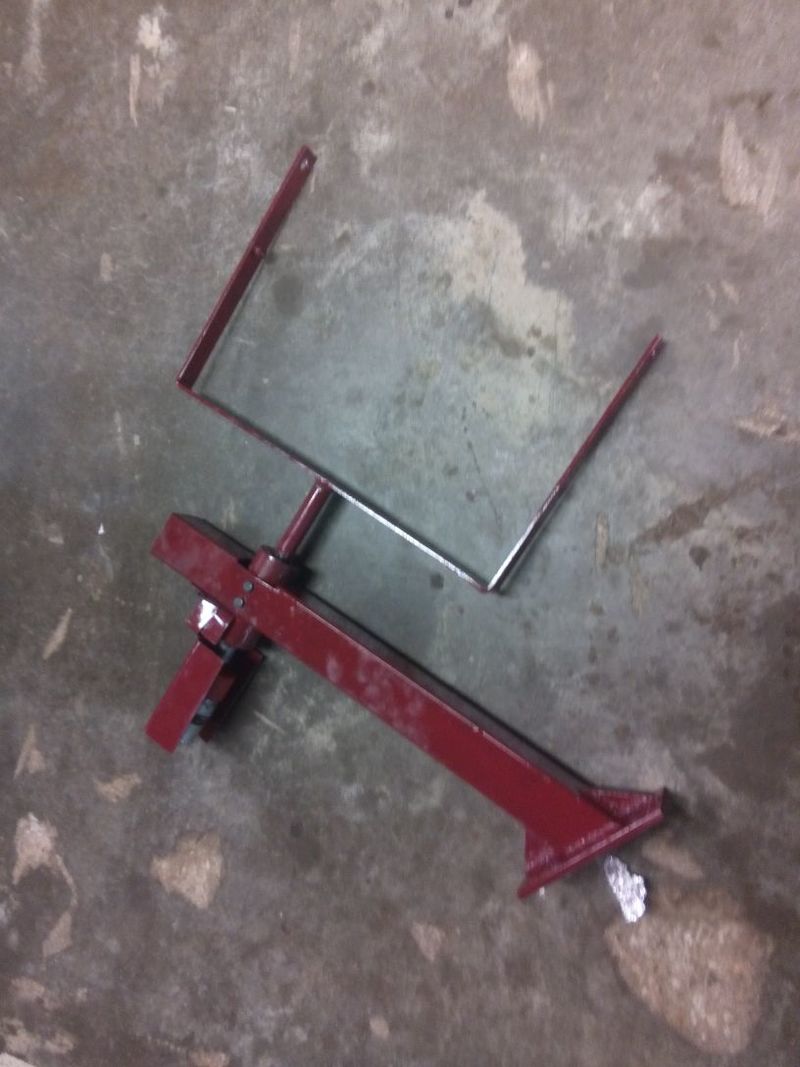
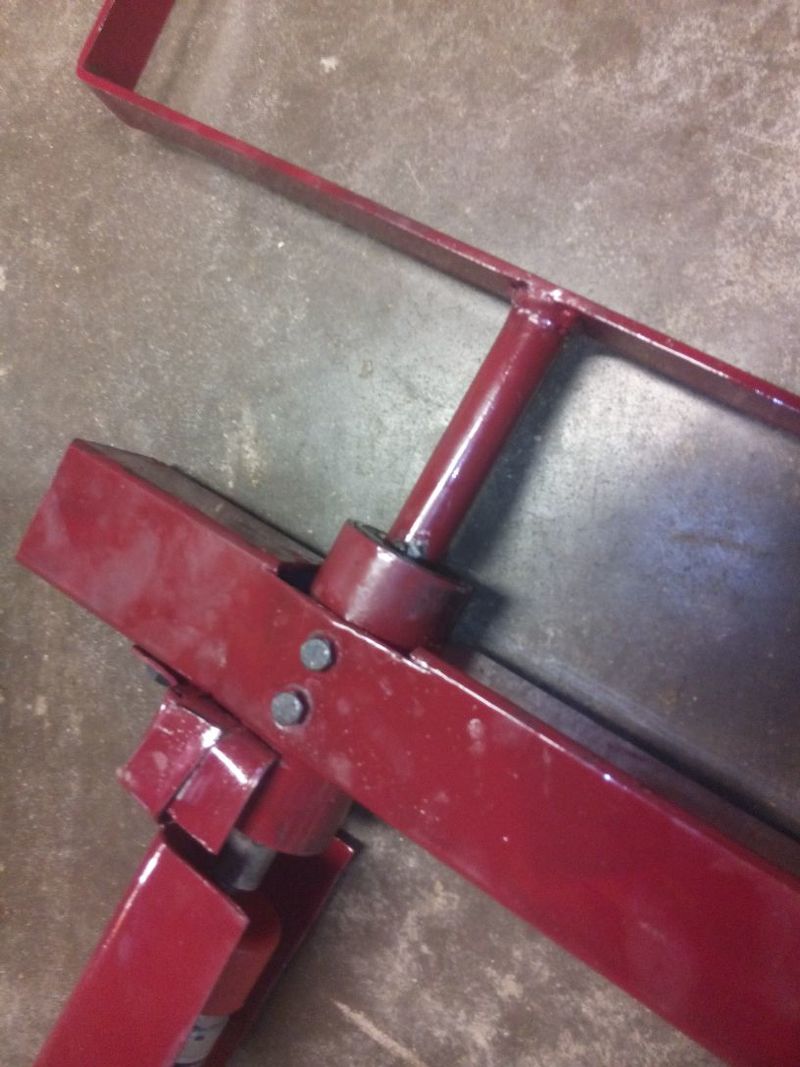
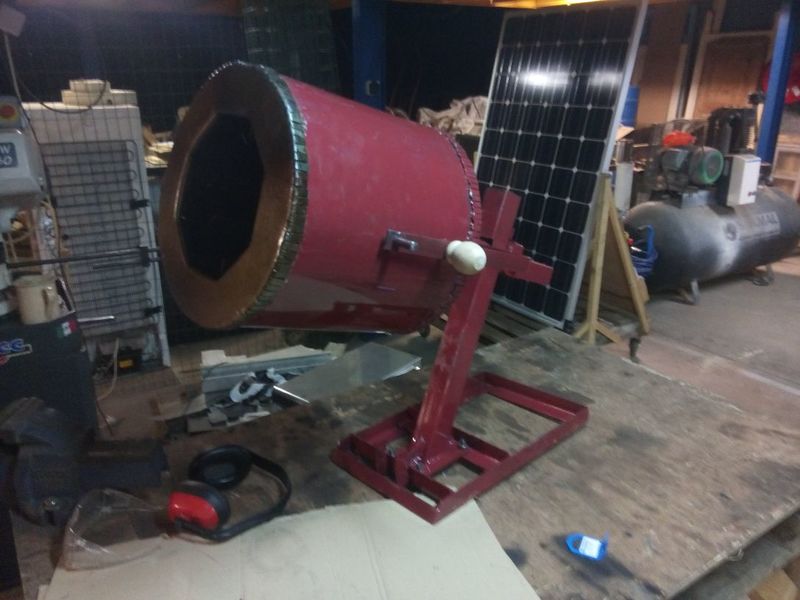
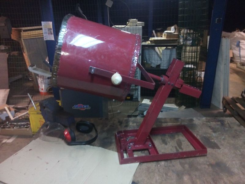
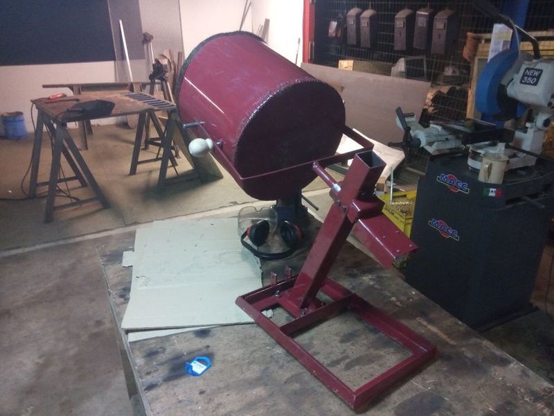
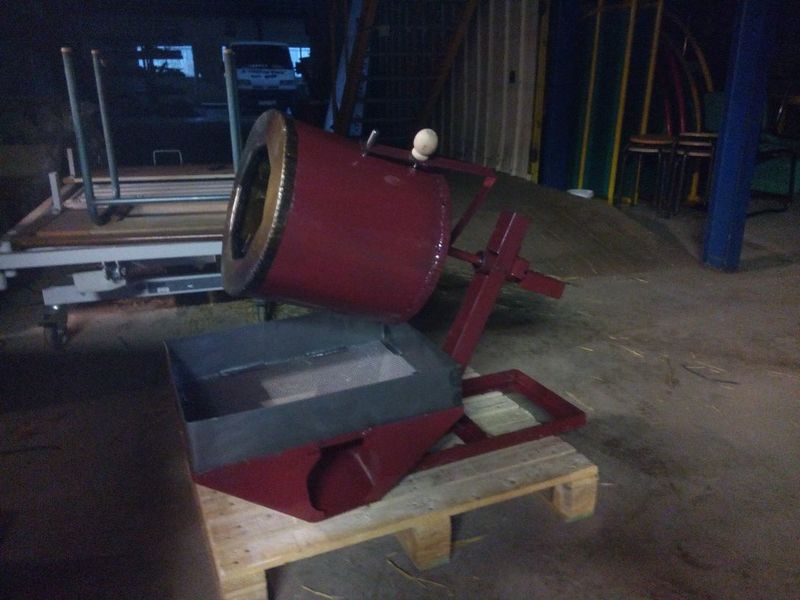
 Français
 English
 Deutsch
 Español
 Italiano
 Português