
(Page créée avec « {{Tuto Details |Main_Picture=Node_Red_Controlled_Web_LED_on_ESP32_with_Raspberry_Pi_4_1.PNG |Main_Picture_annotation={"version":"2.4.6","objects":[{"type":"image","version... ») |
|||
| Ligne 4 : | Ligne 4 : | ||
|Description=<translate>Node Red Controlled Web LED on ESP32 with Raspberry Pi 4</translate> | |Description=<translate>Node Red Controlled Web LED on ESP32 with Raspberry Pi 4</translate> | ||
|Area=Electronics | |Area=Electronics | ||
| − | |Type= | + | |Type=Technique |
|Difficulty=Medium | |Difficulty=Medium | ||
|Duration=2 | |Duration=2 | ||
| Ligne 17 : | Ligne 17 : | ||
You will need the following components for this project: | You will need the following components for this project: | ||
| − | * ESP32 development board | + | *ESP32 development board |
| − | * USB cable to connect the ESP32 to your computer | + | *USB cable to connect the ESP32 to your computer |
| − | * Raspberry Pi with Node-RED | + | *Raspberry Pi with Node-RED |
| − | * Computer with Arduino IDE and PubSubClient library installed</translate> | + | *Computer with Arduino IDE and PubSubClient library installed</translate> |
| + | }} | ||
| + | {{Materials | ||
| + | |Material=<translate></translate> | ||
| + | |Tools=<translate></translate> | ||
}} | }} | ||
| − | |||
{{Tuto Step | {{Tuto Step | ||
|Step_Title=<translate>Get PCBs For Your Projects Manufactured</translate> | |Step_Title=<translate>Get PCBs For Your Projects Manufactured</translate> | ||
| Ligne 57 : | Ligne 60 : | ||
To install the ESP32 board in Arduino IDE, you can follow the instructions in [https://blog.asksensors.com/esp32-led-control-iot-platform-mqtt/ this tutorial] or use the steps below: | To install the ESP32 board in Arduino IDE, you can follow the instructions in [https://blog.asksensors.com/esp32-led-control-iot-platform-mqtt/ this tutorial] or use the steps below: | ||
| − | * Open the preferences window from the Arduino IDE: File > Preferences. | + | *Open the preferences window from the Arduino IDE: File > Preferences. |
| − | * Go to the “Additional Board Manager URLs” field and enter the following URL: | + | *Go to the “Additional Board Manager URLs” field and enter the following URL: https://dl.espressif.com/dl/package_esp32_index.json. |
| − | * Open Boards Manager (Tools > Board > Boards Manager), search for ESP32, and click the install button for the “ESP32 by Espressif Systems”. | + | *Open Boards Manager (Tools > Board > Boards Manager), search for ESP32, and click the install button for the “ESP32 by Espressif Systems”. |
| − | * Select your ESP32 board from Tools > Board menu after installation. | + | *Select your ESP32 board from Tools > Board menu after installation. |
| − | * Open the library manager from Sketch > Include Library > Manage Libraries. | + | *Open the library manager from Sketch > Include Library > Manage Libraries. |
| − | * Search for PubSubClient and click the install button for the “PubSubClient by Nick O’Leary”. | + | *Search for PubSubClient and click the install button for the “PubSubClient by Nick O’Leary”. |
| − | * Restart your Arduino IDE after installation.</translate> | + | *Restart your Arduino IDE after installation.</translate> |
|Step_Picture_00=Node_Red_Controlled_Web_LED_on_ESP32_with_Raspberry_Pi_4_8.PNG | |Step_Picture_00=Node_Red_Controlled_Web_LED_on_ESP32_with_Raspberry_Pi_4_8.PNG | ||
|Step_Picture_01=Node_Red_Controlled_Web_LED_on_ESP32_with_Raspberry_Pi_4_9.PNG | |Step_Picture_01=Node_Red_Controlled_Web_LED_on_ESP32_with_Raspberry_Pi_4_9.PNG | ||
| Ligne 300 : | Ligne 303 : | ||
{{Tuto Step | {{Tuto Step | ||
|Step_Title=<translate>Conclusion</translate> | |Step_Title=<translate>Conclusion</translate> | ||
| − | |Step_Content=<translate><section id="story"> | + | |Step_Content=<translate><section id="story" data-origID="story" > |
In this tutorial, we have seen how to control the LED with Node-Red and MQTT Server. | In this tutorial, we have seen how to control the LED with Node-Red and MQTT Server. | ||
</section></translate> | </section></translate> | ||
| Ligne 306 : | Ligne 309 : | ||
}} | }} | ||
{{Notes | {{Notes | ||
| − | |Notes=<translate></translate> | + | |Notes=<translate>Link was incorrect, so I have corrected it.</translate> |
}} | }} | ||
{{PageLang | {{PageLang | ||
| + | |Language=en | ||
|SourceLanguage=none | |SourceLanguage=none | ||
|IsTranslation=0 | |IsTranslation=0 | ||
| − | |||
}} | }} | ||
{{Tuto Status | {{Tuto Status | ||
|Complete=Published | |Complete=Published | ||
}} | }} | ||
Version actuelle datée du 2 juin 2024 à 15:46
Node Red Controlled Web LED on ESP32 with Raspberry Pi 4

Difficulté
Moyen
Durée
2 heure(s)
Catégories
Électronique
Coût
70 USD ($)
Sommaire
- 1 Introduction
- 2 Étape 1 - Get PCBs For Your Projects Manufactured
- 3 Étape 2 - Create a Device on Qubitro
- 4 Étape 3 - Flash ESP32 with Arduino IDE
- 5 Étape 4 - Connect LED to ESP32
- 6 Étape 5 - Write Code for ESP32
- 7 Étape 6 - Create Node-RED Flow
- 8 Étape 7 - Conclusion
- 9 Notes et références
- 10 Commentaires
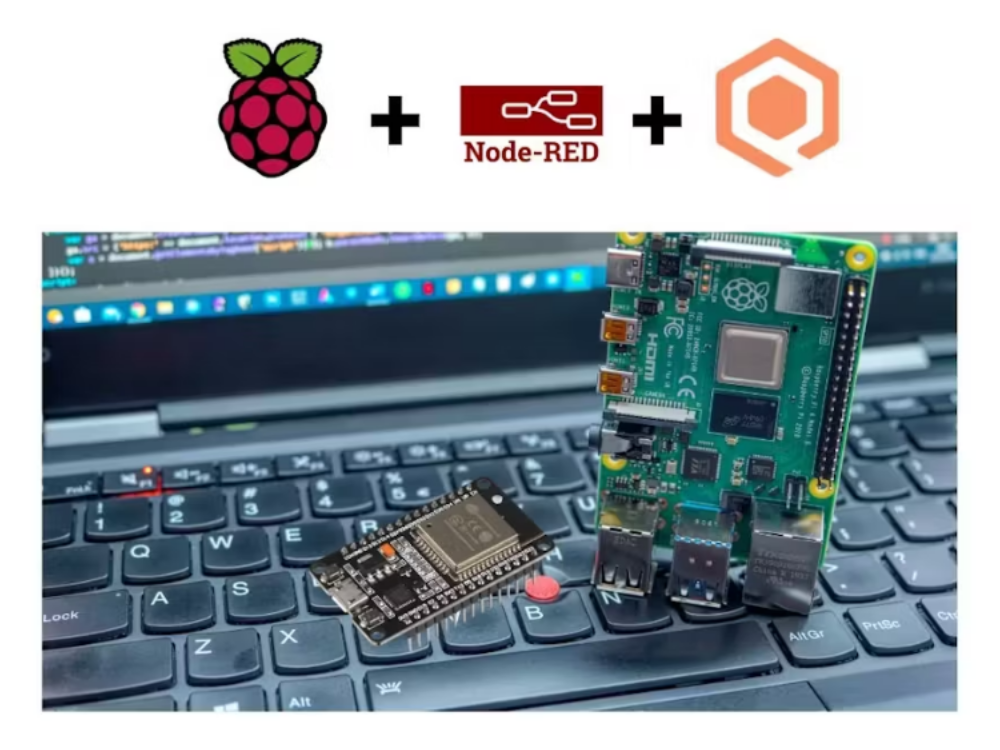
Introduction
In this tutorial, you will learn how to use Node-RED, a visual programming tool for the Internet of Things (IoT), to control an LED on an ESP32 board with a Raspberry Pi as the MQTT broker. MQTT is a lightweight and simple messaging protocol that allows devices to communicate with each other over a network.
You will need the following components for this project:
- ESP32 development board
- USB cable to connect the ESP32 to your computer
- Raspberry Pi with Node-RED
- Computer with Arduino IDE and PubSubClient library installed
Matériaux
Outils
Étape 1 - Get PCBs For Your Projects Manufactured
You must check out PCBWAY for ordering PCBs online for cheap!
You get 10 good-quality PCBs manufactured and shipped to your doorstep for cheap. You will also get a discount on shipping on your first order. Upload your Gerber files onto PCBWAY to get them manufactured with good quality and quick turnaround time. PCBWay now could provide a complete product solution, from design to enclosure production. Check out their online Gerber viewer function. With reward points, you can get free stuff from their gift shop

Étape 2 - Create a Device on Qubitro
The first step is to create a device on the Qubitro platform. A device represents your physical device (Raspberry Pi) on the cloud. You need to create a device to obtain the MQTT credentials and topics for your Raspberry Pi.
To create a device on Qubitro, follow these steps:
1. Log in to your Qubitro account and create a new project
2. Then go to the Devices page, select MQTT as the communication protocol, and click Next.
3. Enter all the details.
4. Copy the Device ID, Device Token, Hostname, Port, Publish Topic, and Subscribe Topic. You will need these values later in the code. Click Finish.
You have successfully created a device on Qubitro. You can see your device on the Devices page.


Étape 3 - Flash ESP32 with Arduino IDE
The ESP32 is a powerful and versatile microcontroller that can run Arduino code. You will use the Arduino IDE to program the ESP32 and make it communicate with the MQTT broker using the PubSubClient library.
To install the ESP32 board in Arduino IDE, you can follow the instructions in this tutorial or use the steps below:
- Open the preferences window from the Arduino IDE: File > Preferences.
- Go to the “Additional Board Manager URLs” field and enter the following URL: https://dl.espressif.com/dl/package_esp32_index.json.
- Open Boards Manager (Tools > Board > Boards Manager), search for ESP32, and click the install button for the “ESP32 by Espressif Systems”.
- Select your ESP32 board from Tools > Board menu after installation.
- Open the library manager from Sketch > Include Library > Manage Libraries.
- Search for PubSubClient and click the install button for the “PubSubClient by Nick O’Leary”.
- Restart your Arduino IDE after installation.


Étape 4 - Connect LED to ESP32
The LED is a simple device that emits light when current flows through it. You will connect the LED to one of the GPIO pins of the ESP32 and control its state (on or off) with MQTT messages.
In my case I'm going to use the onboard LED in the ESP32 Dev board.

Étape 5 - Write Code for ESP32
The code for the ESP32 will do the following tasks:
- Connect to your Wi-Fi network
- Connect to the Qubitro MQTT broker on Raspberry Pi
- Receive messages from “output” and turn on or off the LED accordingly
<your_ssid>, <your_password>, <your_Qubtro_Credientials> with your own values.void setup()
{
pinMode(Relay1, OUTPUT);
Serial.begin(115200);
setup_wifi();
client.setServer(mqtt_server, 1883);
client.setCallback(callback);
}
void loop()
{
if (!client.connected())
{
reconnect();
}
client. Loop();
}


Étape 6 - Create Node-RED Flow
The Node-RED flow will do the following tasks:
- Connect to the MQTT broker on Raspberry Pi
- Subscribe to a topic named “output”
- Publish messages “true” or “false” to a topic named “output”
- Create a dashboard with a button and a text node
[
    {
        "id": "eb8f9c0d054be30c",
        "type": "tab",
        "label": "Flow 2",
        "disabled": false,
        "info": "",
        "env": []
    },
    {
        "id": "4ce6cd876fd5441f",
        "type": "mqtt out",
        "z": "eb8f9c0d054be30c",
        "name": "",
        "topic": "output",
        "qos": "",
        "retain": "",
        "respTopic": "",
        "contentType": "",
        "userProps": "",
        "correl": "",
        "expiry": "",
        "broker": "6d40b7b21c734b53",
        "x": 870,
        "y": 240,
        "wires": []
    },
    {
        "id": "974a7a8bb6db9bf9",
        "type": "mqtt in",
        "z": "eb8f9c0d054be30c",
        "name": "",
        "topic": "output",
        "qos": "2",
        "datatype": "auto-detect",
        "broker": "6d40b7b21c734b53",
        "nl": false,
        "rap": true,
        "rh": 0,
        "inputs": 0,
        "x": 670,
        "y": 320,
        "wires": [
            [
                "d0dc7378c7bfb03b",
                "f1219a2eeabe825f"
            ]
        ]
    },
    {
        "id": "d0dc7378c7bfb03b",
        "type": "debug",
        "z": "eb8f9c0d054be30c",
        "name": "debug 4",
        "active": true,
        "tosidebar": true,
        "console": false,
        "tostatus": false,
        "complete": "payload",
        "targetType": "msg",
        "statusVal": "",
        "statusType": "auto",
        "x": 880,
        "y": 320,
        "wires": []
    },
    {
        "id": "6bd227b280e372b7",
        "type": "ui_switch",
        "z": "eb8f9c0d054be30c",
        "name": "",
        "label": "Light One",
        "tooltip": "",
        "group": "cd687a95.00e108",
        "order": 0,
        "width": 0,
        "height": 0,
        "passthru": true,
        "decouple": "false",
        "topic": "topic",
        "topicType": "msg",
        "style": "",
        "onvalue": "true",
        "onvalueType": "bool",
        "onicon": "",
        "oncolor": "",
        "offvalue": "false",
        "offvalueType": "bool",
        "officon": "",
        "offcolor": "",
        "animate": false,
        "x": 680,
        "y": 240,
        "wires": [
            [
                "4ce6cd876fd5441f"
            ]
        ]
    },
    {
        "id": "f1219a2eeabe825f",
        "type": "ui_text",
        "z": "eb8f9c0d054be30c",
        "group": "cd687a95.00e108",
        "order": 1,
        "width": "6",
        "height": "2",
        "name": "",
        "label": "Status : ",
        "format": "{{msg.payload}}",
        "layout": "row-center",
        "x": 1060,
        "y": 320,
        "wires": []
    },
    {
        "id": "6d40b7b21c734b53",
        "type": "mqtt-broker",
        "name": "Qubitro Downlink",
        "broker": "broker.qubitro.com",
        "port": "1883",
        "clientid": "",
        "autoConnect": true,
        "usetls": false,
        "protocolVersion": "4",
        "keepalive": "60",
        "cleansession": true,
        "autoUnsubscribe": true,
        "birthTopic": "r43MsJYzcVwZtUXVfZo6XD0Ym7CRegewPQXMt$ho",
        "birthQos": "0",
        "birthPayload": "",
        "birthMsg": {},
        "closeTopic": "",
        "closeQos": "0",
        "closePayload": "",
        "closeMsg": {},
        "willTopic": "",
        "willQos": "0",
        "willPayload": "",
        "willMsg": {},
        "userProps": "",
        "sessionExpiry": ""
    },
    {
        "id": "cd687a95.00e108",
        "type": "ui_group",
        "name": "ESP32 Home Controller",
        "tab": "aa146f4d.b53ca",
        "order": 1,
        "disp": true,
        "width": "6",
        "collapse": false
    },
    {
        "id": "aa146f4d.b53ca",
        "type": "ui_tab",
        "name": "Demo Lab",
        "icon": "dashboard",
        "order": 1,
        "disabled": false,
        "hidden": false
    }
]Then click on the Qubitro uplink pallet and edit the property.
Here you need to replace your connection details and credentials.
Next, just deploy the flow. And navigate to the /ui of the node-red server.
Here you can toggle the switch to turn the lead on and off.
Also, open the serial monitor and check the node-red response.
Étape 7 - Conclusion

Notes et références
Link was incorrect, so I have corrected it.
Published
 Français
 English
 Deutsch
 Español
 Italiano
 Português