(set pageLanguageSource property) |
(set pageLanguageSource property) |
||
| Ligne 76 : | Ligne 76 : | ||
<!--T:71--> | <!--T:71--> | ||
| − | {{Info| | + | {{Info|Often the screw holes will be misprinted, I'ts not very important, the screw will find its way amidst the plastic mess.}}</translate> |
}} | }} | ||
{{ {{tntn|Tuto Step}} | {{ {{tntn|Tuto Step}} | ||
| Ligne 303 : | Ligne 303 : | ||
<!--T:74--> | <!--T:74--> | ||
| − | {{Info| | + | {{Info|If you can't find any Black Patafix [or blue-tac], you can make your own by mixing some basic blue-tac in some Indian ink. [you'll have ink on your nails for 2 days at least....]}} |
<!--T:75--> | <!--T:75--> | ||
| Ligne 394 : | Ligne 394 : | ||
<!--T:78--> | <!--T:78--> | ||
| − | {{Info| | + | {{Info|I advice to set the exposure time to 1/60° but it can be different on your shutter, depending of the wheels you use, your finger strength, etc. |
If your first film is over exposed you'll have to lower this value (1/40° or even less) and if it's under exposed you must increase this value ! [Don't make the same mistake I did for my second film.. I got mixed up and increased my exposing time although my first film was already over exposed]}} | If your first film is over exposed you'll have to lower this value (1/40° or even less) and if it's under exposed you must increase this value ! [Don't make the same mistake I did for my second film.. I got mixed up and increased my exposing time although my first film was already over exposed]}} | ||
| Ligne 414 : | Ligne 414 : | ||
<!--T:82--> | <!--T:82--> | ||
| − | {{Pin| | + | {{Pin|For the first films I advice to use bracketing before you get your perfect settings. Take a picture with the exposure meter advice settings, and two more, one with an aperture up, and another with aperture down.}} |
<!--T:83--> | <!--T:83--> | ||
Version du 27 juin 2018 à 11:17
Sommaire
- 1 Introduction
- 2 Étape 1 - Print the back
- 3 Étape 2 - Assemble the back
- 4 Étape 3 - Print the parts of the Shutter
- 5 Étape 4 -
- 6 Étape 5 -
- 7 Étape 6 - Shutter and Actuator
- 8 Étape 7 - Put the ActuatorCover in place
- 9 Étape 8 - Shutter is complete
- 10 Étape 9 - Print the parts of the Viewfinder
- 11 Étape 10 -
- 12 Étape 11 -
- 13 Étape 12 -
- 14 Étape 13 - Lightproof everything!
- 15 Étape 14 - Lightproofing
- 16 Étape 15 - Assemble everything!
- 17 Étape 16 - Load film
- 18 Étape 17 - Take pictures!
- 19 Notes et références
- 20 Commentaires
Introduction
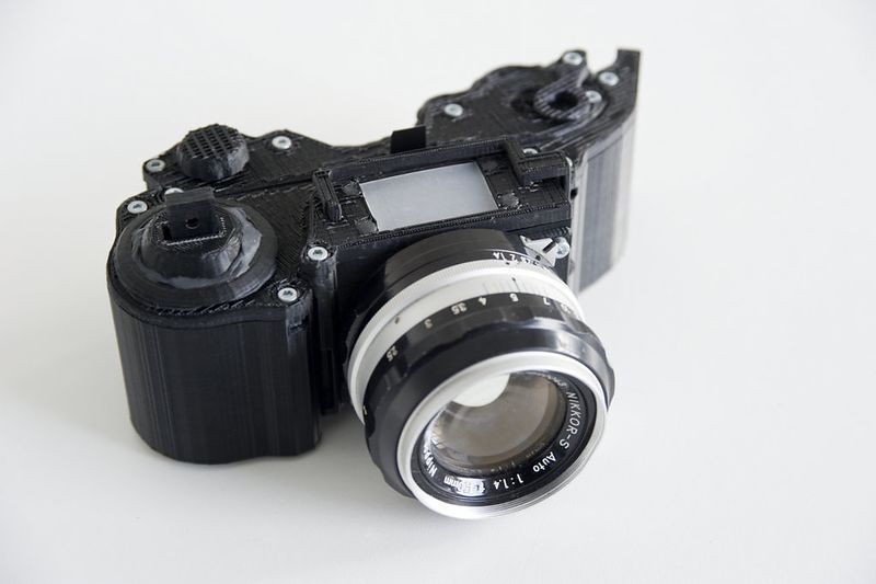
The OpenReflex is an Open-Source analog camera with a mirror Viewfinder and an awesome finger activated mechanic shutter (running ~ 1/60°s). What's more, it's compatible with any photographic lens with custom mount ring. All the pieces easily printable on an recent RepRap-like ABS 3D-printer without using support material ! Everything should print in less than 15h and anyone should be able to assemble it within 1h.
All parts are separate ( Film receiver, Shutter and Viewfinder ) to simplify builds and modifications.
Matériaux
- ~250g black ABS (7€)
- 3 M3 bearing (3€)
- Some M3 screw and bolts
- 1 Black PET 0.3mm sheet [plastic spacer]
- 1 Clear translucent plastic sheet
- 1 Little piece of mirror 1.5mm thick
- 16 3mm cubic magnete (3€~)
- 1 Finger Skate truck (5€~)
- 1 Black Sugru sachet (3€~)
Outils
- A recent RepRap-like 3D-Printer, prefer one that can print ABS [I used a MakerBot Replicator2X],
- A CNC cutting tool (Vinyl cutter or Laser cutter) [I used a Silouhette Cameo plotter and an Epilog Lasercutter],
- A glass-cutter,
- A screwdriver,
- An allen key,
- Some glasspaper.
Étape 1 - Print the back
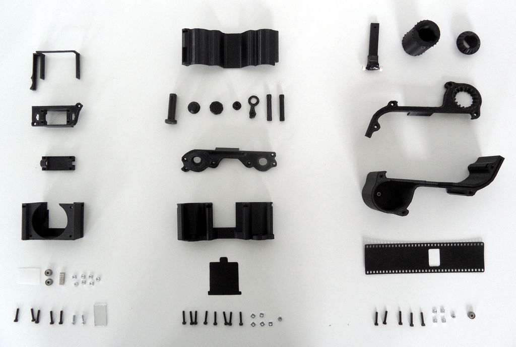
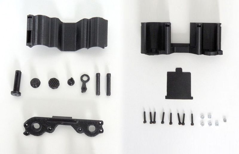
Print All parts:
- Body : ~ 2h50
- Cover : ~0h50
- BackCover : ~1h30 ? (I forgot to check...)
- All the rest : ~1h
[ FilmGuide X2 - Rewinder - RewinderCover - Unwinder - UnwinderP2 - UnwinderButton ]
Cut the BackShutter.
My 3D-printer settings : I sliced my mesh using MakerWare (the only non-OpenSource software I used...) with these basic settings : Infill 15% with 3 shells with 0.27 thick layers. The printer I used made very clean parts so I didn't need lots of shells and a big infill to get properly lightproof pieces. So depending on your printer you may need to modify these settings. What's most important is that your pieces are lightproof, you don't need pristine HD print for these parts.
Once you've printed everything, cleanup your pieces if necessary. Any hole will be filled later on with some sugru to improve lightproofing.
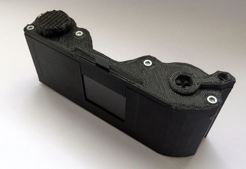
Étape 2 - Assemble the back
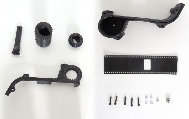
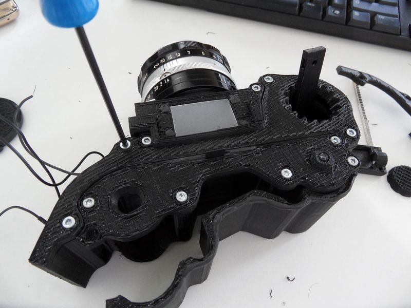
1- Start by putting the two M3 hexagonal nuts in the holes provided for on the Body. It's a tight fit, so you'll need to push a bit. You can screw a screw from the other side for pull the nut.
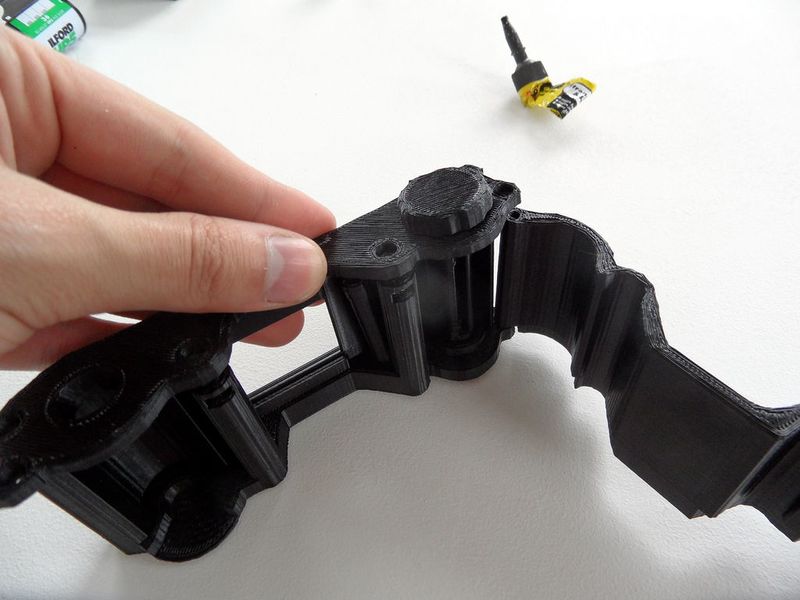
2- Install the BackCover on its axis and insert the nut & bolt. The BackCover should fit nicely and rotate freely on its axis. Also set the BackShutter on his groove on the Body.
3- Put the UnwinderP2 and the UnwinderButton in place in the Cover. They should rotate, but not too much.
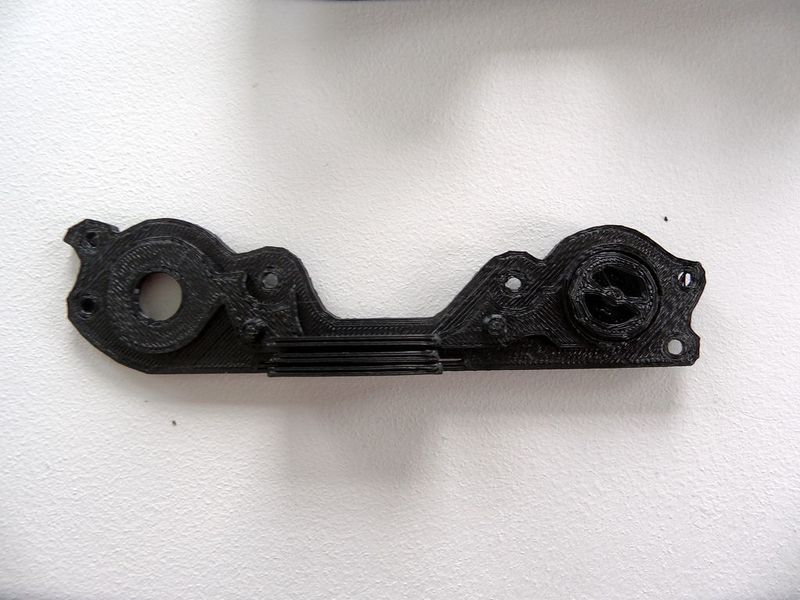
4- Set the Unwinder and the two FilmGuides in place in the Body. Put the Cover over all of this. You'll have to turn the UnwinderButton to align it with the Unwinder. Note : If the FilmGuide don't rotate on their axis it's not a problem.
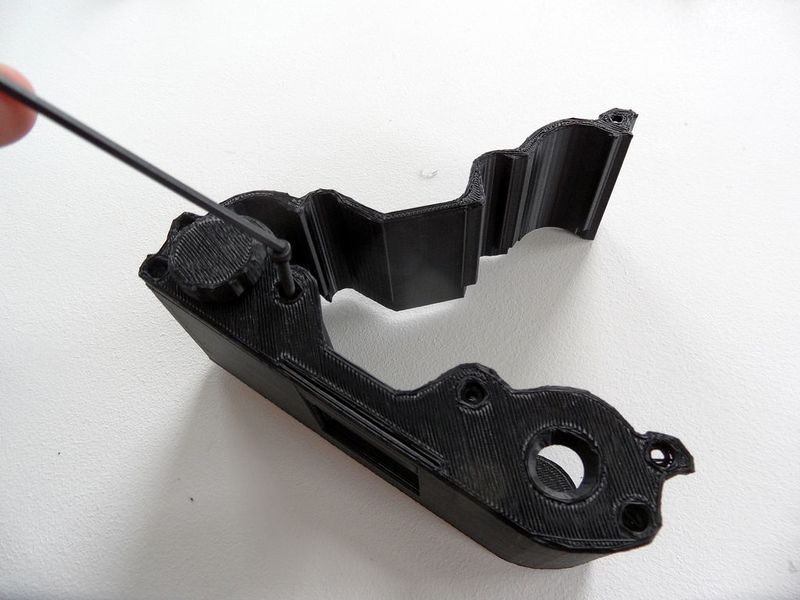
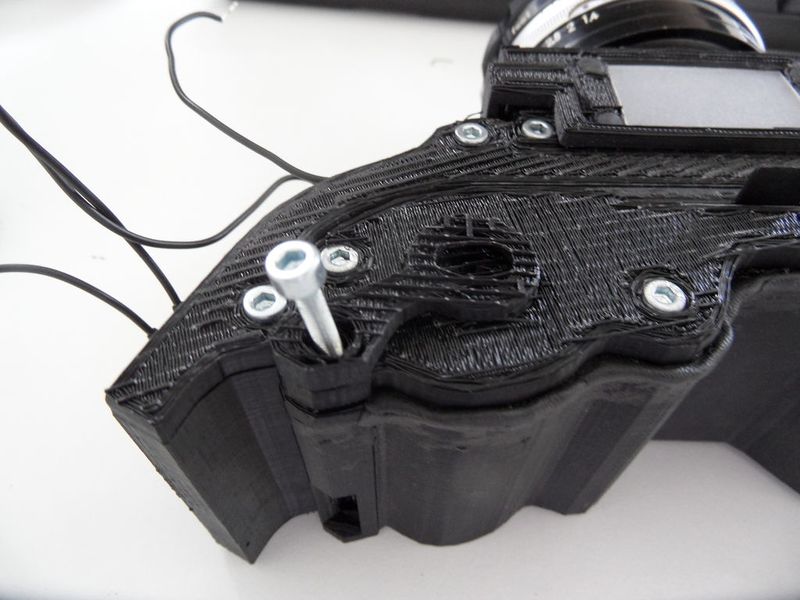
5- Once everything is in place, put squared nuts in the columns and screw them in place through the Cover.
6- Algih the BackCover with the Cover and screw them together. Everything should fit in place, the UnwinderButton should make the Unwinder turn with some friction and the BackShutter should slide on its groove.
All done ! For the Rewinder and the final light proofing we'll see this later. ;)
Étape 3 - Print the parts of the Shutter
Print All parts:
- Body: ~ 5h30
- Cover: ~1h50
- Wheel: ~3h20 (Print this with an HD profile, layer as thin as possible !)
- Actuator: ~ less than 1h, print with support (forgot to check...)
- ActuatorCover: ~0h40
Cut the Shutter.svg
Clean All the parts, especially the Body, some filament can be misprinted and block the path of the Shutter. Don't hesitate to use some glasspaper.
Étape 4 -
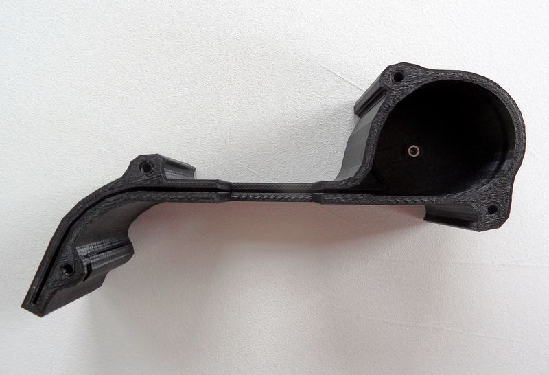
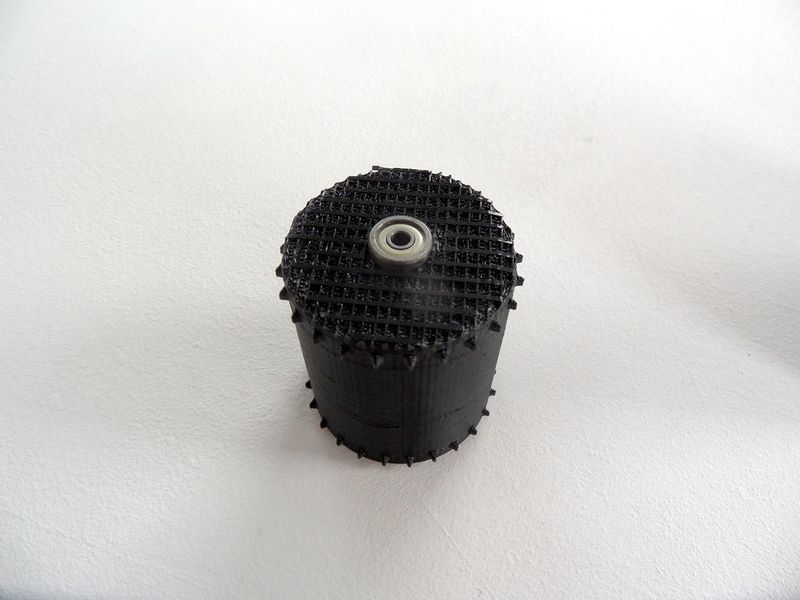
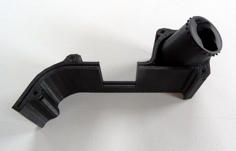
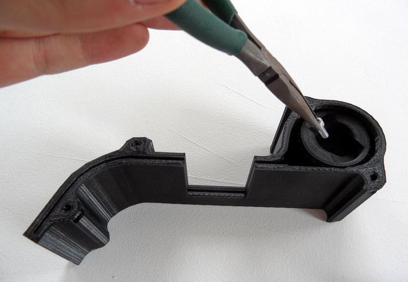
Prepare the parts, set in place the bearing under the Wheel. It's a tight fit, set the bearing on the alignment then push ! If some misprinted plastic hinders the alignment, pull off the bearing, clean the Wheel hole and try again.
Put the hexagonal nut in place in the bottom of the Body. It's a tight fit again so push a little.
Put the Wheel in the Body.
Étape 5 -
Screw it from the top then put a nut at the other side. The Wheel should turn fine without too much friction. If it's not in the axis pull the wheel out and check the nut under and the bearing. A little misalignment isn't important and should be corrected by the Shutter.
Étape 6 - Shutter and Actuator
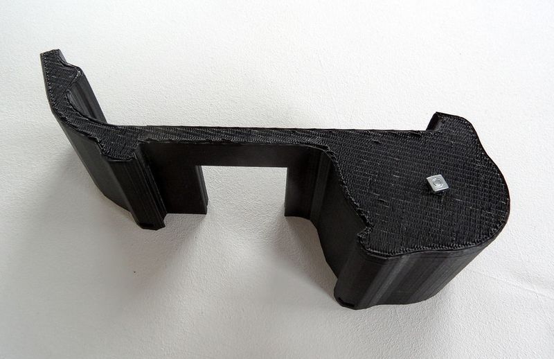
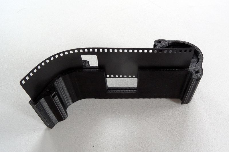
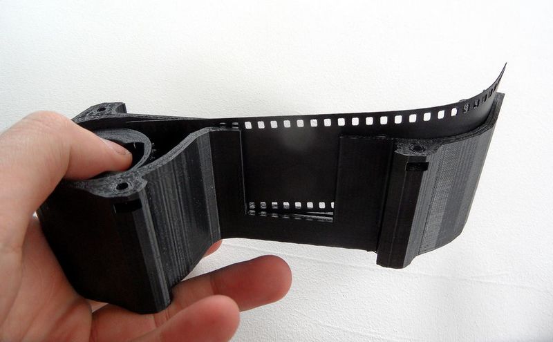
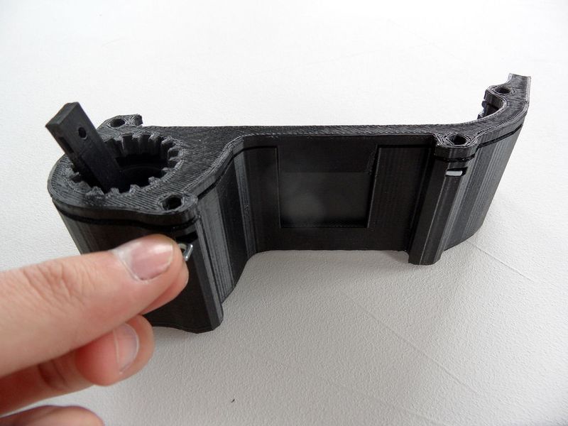
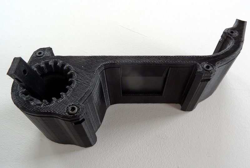
Put the Shutter in place. The long part in direction of the Wheel. It's not very easy, you'll have to bend it and push a bit on the Wheel. When perforations are all in place on the Wheel everything should be fine.
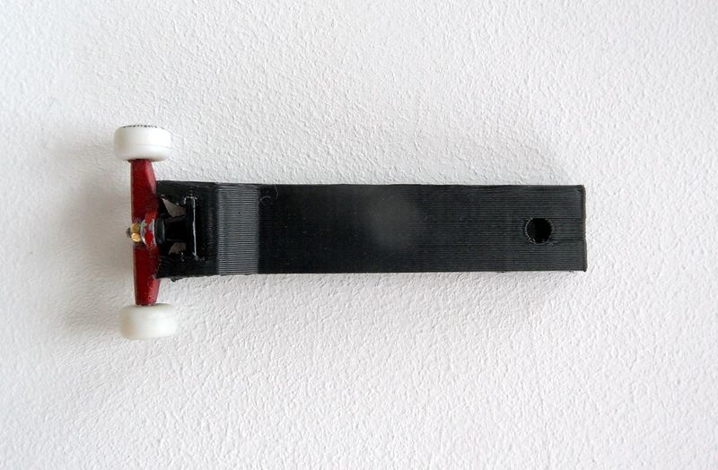
Build your finger skate truck and fix it on the Actuator, use moderate force.
Put the Actuator in the Wheel, set the Cover in place and screw it in place just like for the Back.
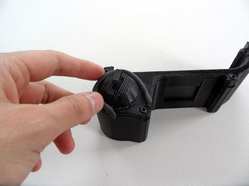
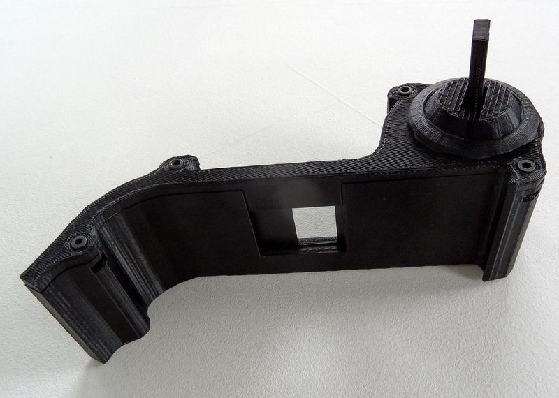
Étape 7 - Put the ActuatorCover in place
Turn the Wheel to stumble the Shutter, then put the ActuatorCover in place to keep the rotation of the Actuator. Fix the ActuatorCover with some Patafix [Blue-tac]. (we're using blue-tac in case the Wheel moves and we need to put it back into place)
Étape 8 - Shutter is complete
All done! We'll see later how to use it.
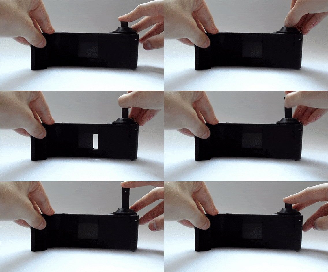
In this little video, you can see how the shutter is working
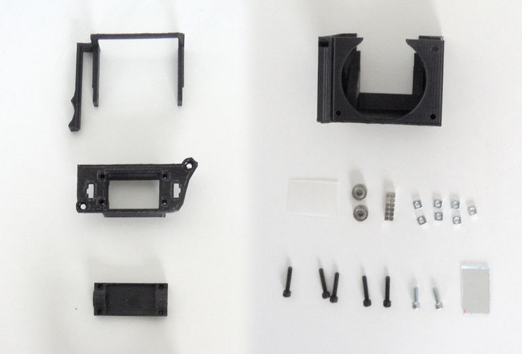
Étape 9 - Print the parts of the Viewfinder
You'll need:
- 12 3mm magnet cube
- 1 piece of mirror 1.5mm thick (file can be adapted for other thickness)
- 1 clear translucent plastic or a thin sanded glass to cut
- 5 M3 square nuts
- 4 M3 nuts
- 2 M3 bearings
- 2 M3X10 Screw
- 2 M3 Screw (X10 or X16)
Print All parts:
- Body : ~ 1h25
- Top
- SuppMirror
- MirrorActuator : ~ 45mn
- NikonRing : ~ 40mn
Cut a mirror a the right size. Cut a piece of clear translucent plastic at the right size.
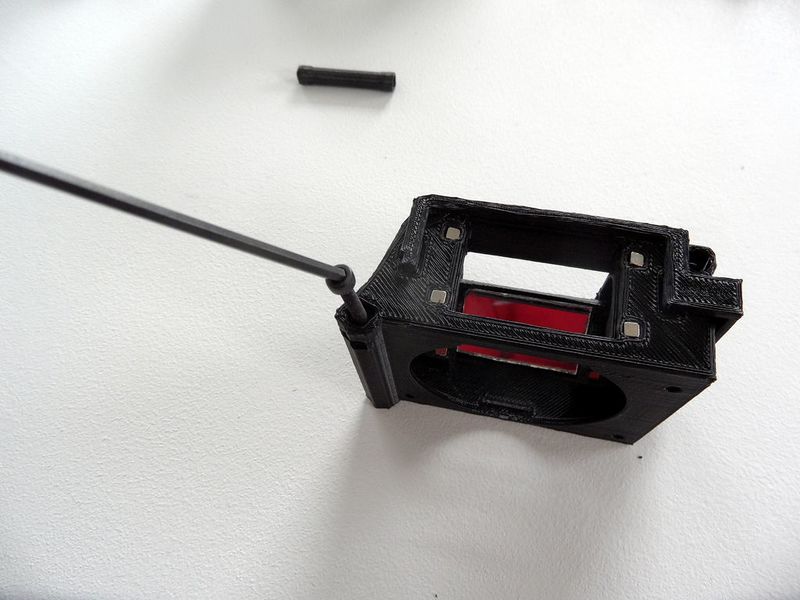
Étape 10 -
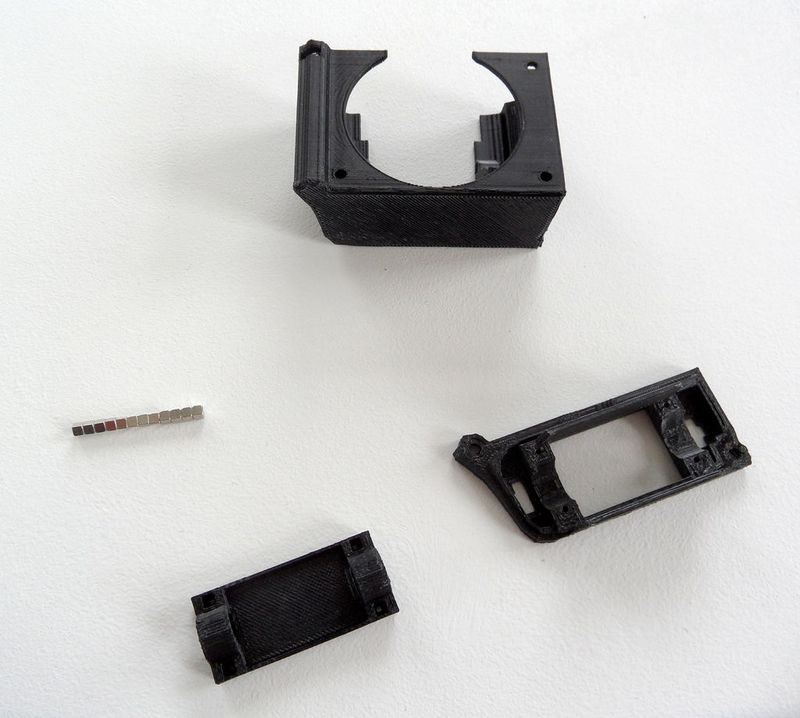
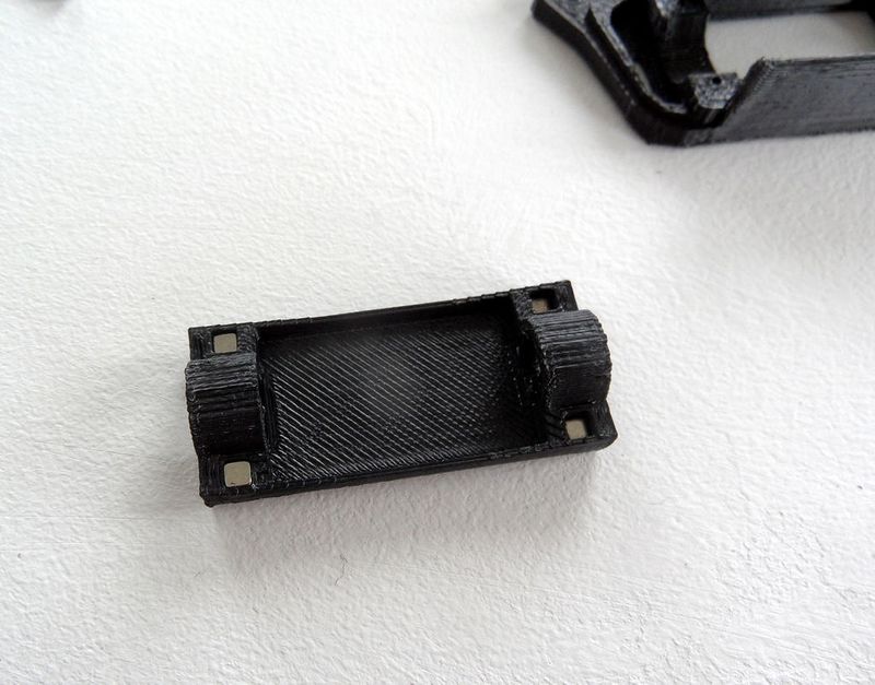
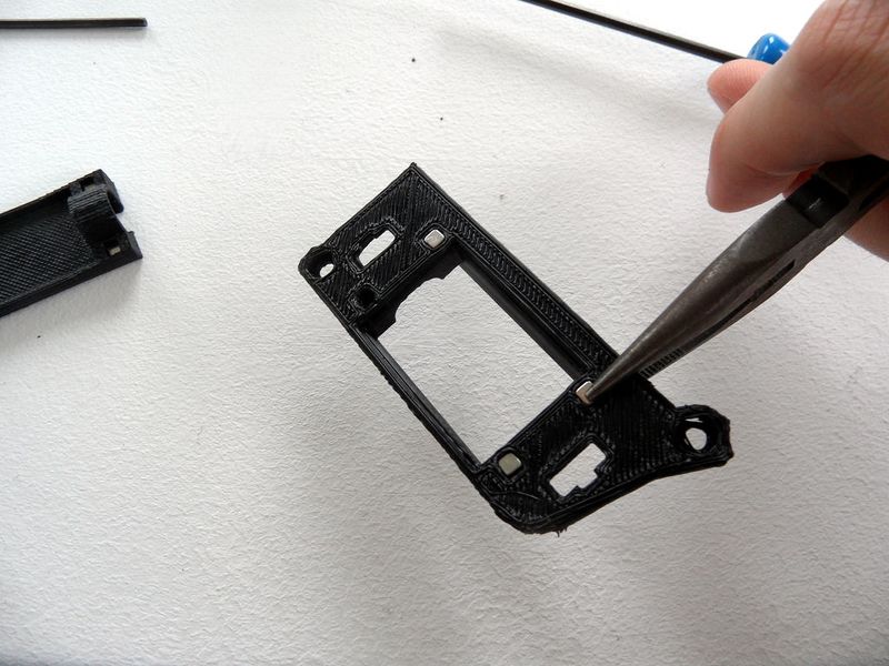
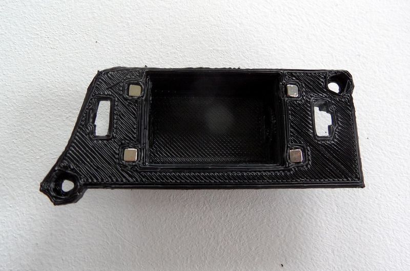
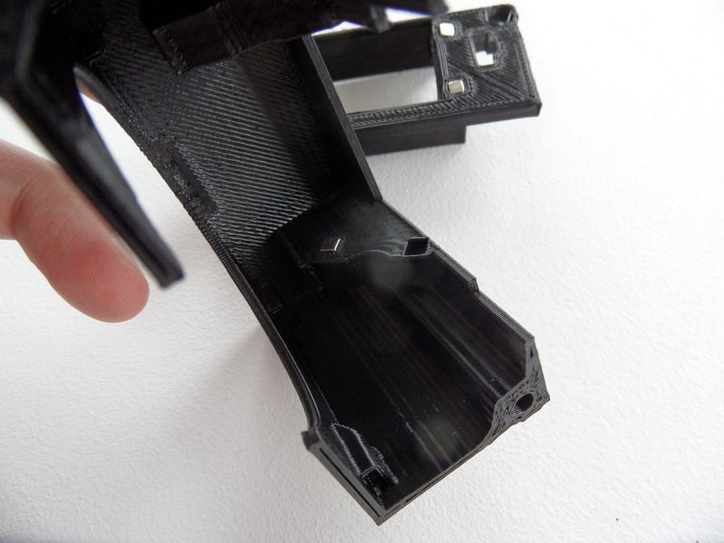
1- Set in place all the magnets, beggin with the SuppMirror then do the Body and Top. For the SuppMirror and the top you'll have to push them a bit, i used a pliers for the Top. Always check the magnet polarity before you install them ! The MirrorSupp should be attracted by the Body with the mirror on the top. If you get the magnet polarity wrong you're in trouble, they're a pain to recover.
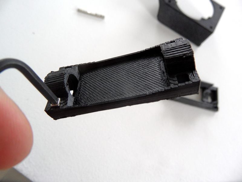
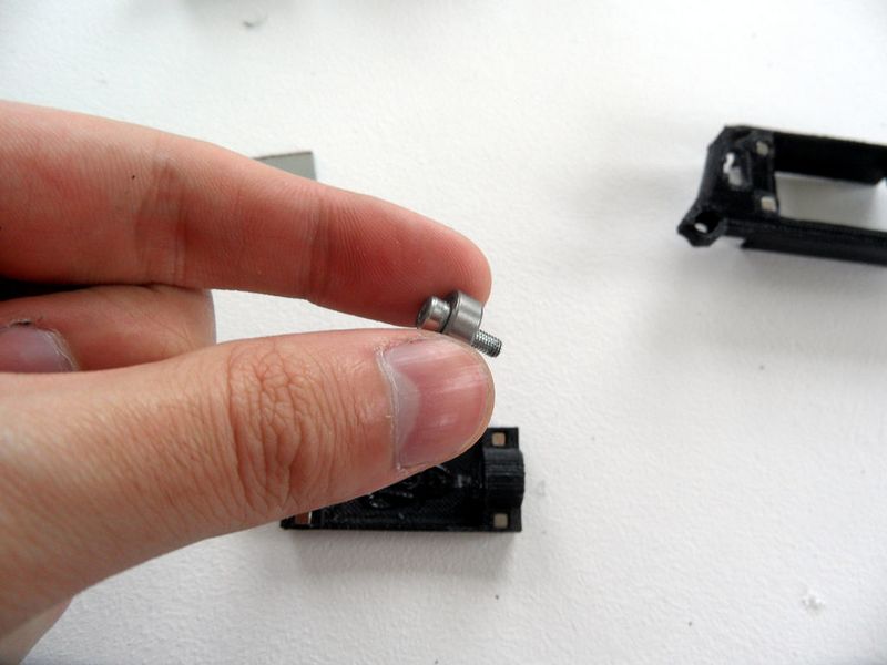
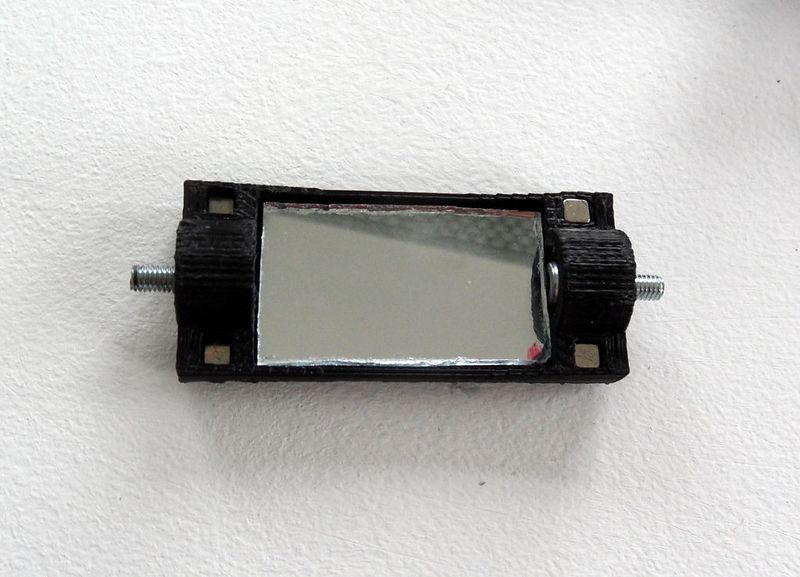
2- Prepare the bearings, block them with an M3X10 screw and a nut. Then plug them in the SuppMirror, screw head oriented towards the inside. [Note : The SuppMirror bridge may crack sometimes, don't worry, it's not a big deal.]
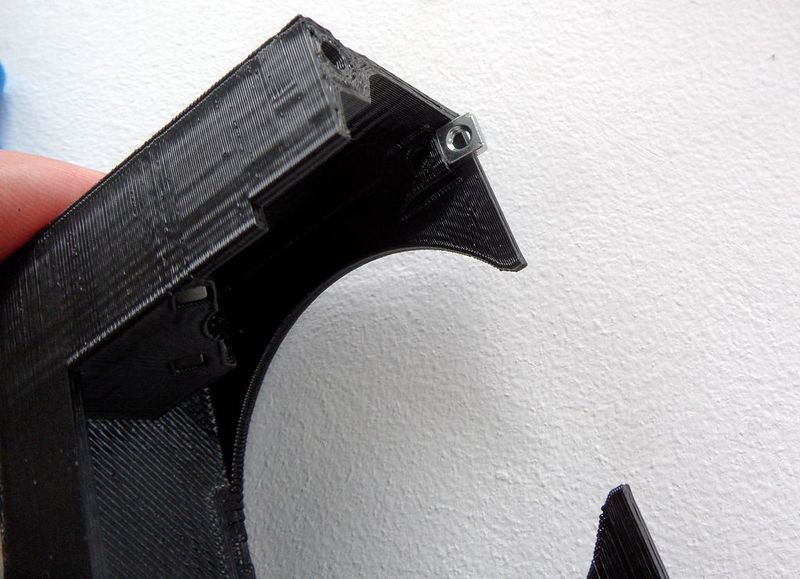
3- Put the square nuts in place inthe holes around the lens mount space. Push them in the bottom then block them with a bit of Patafix [Blue-tac] or Sugru.
Étape 11 -
4- Glue the mirror on the SuppMirror.
5- Set the MirrorActuator in place through the Top, then put the MirrorSupp in. The MirrorActuator should bend a bit, bend it to place the MirrorSupp screw through the holes of the actuator, then put the nuts and screw them to keep them in place.
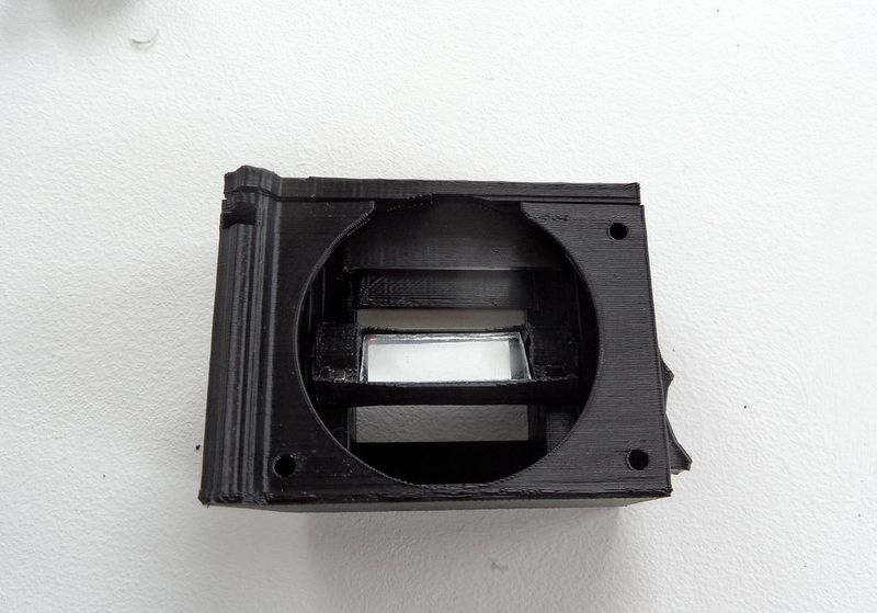
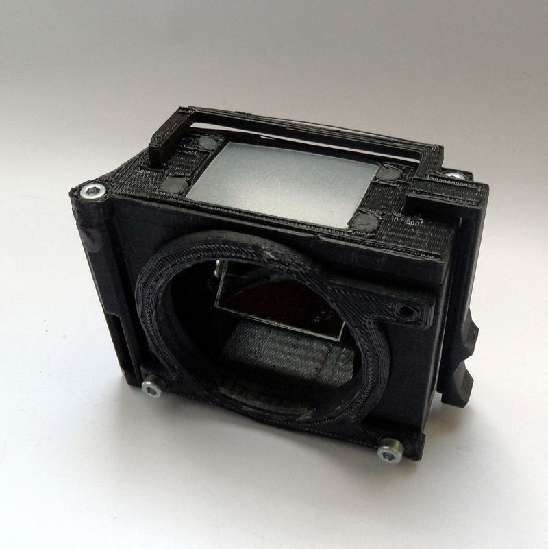
6- Everithing should be ok now, put the Top on the Body and screw them together like for the others parts. The Cover isn't perfect yet so you'll have to push a bit to set it in the right place. ;)
7- To finish put the viewing screen in place (the clear translucent plastic), it should fit in the hole of the Cover, fix it in place with a bit of glue, Sugru or Blue-tac.
8- You can now fix you favorite MountRing and screw it in front of the viewfinder to allow you to mount your lens.
Étape 12 -
All done ! The mirror should go up and down when using the actuator. (not perfect yet but it's working)
Note : Sometimes when being a bit rough, the mirror will flip on its axis. You can put it back into place by brutalizing it a bit (not to hard) or just by removing the lens and turning it by hand.
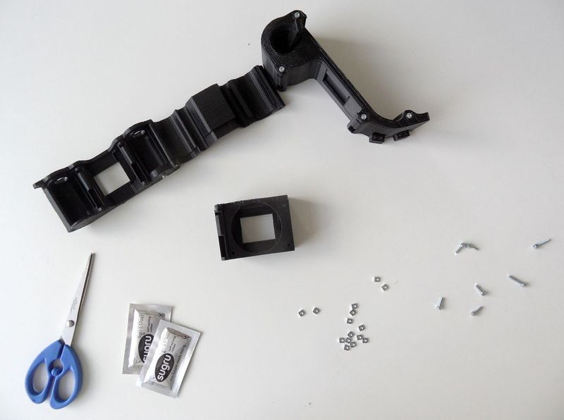
Étape 13 - Lightproof everything!
Now we have all the parts built we have to make sure everything is lightproof like it should !
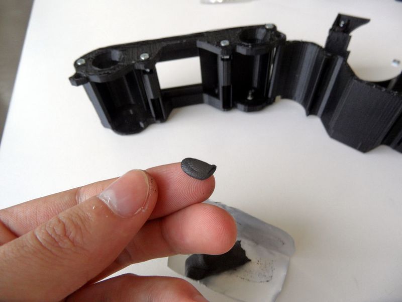
So, it's the moment to get your Sugru out! (or black blue-tac)
Start by filling all the holes of the bolts, you can also do this on the bolts on the Viewfinder and cover the magnets.
Étape 14 - Lightproofing
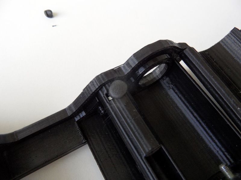
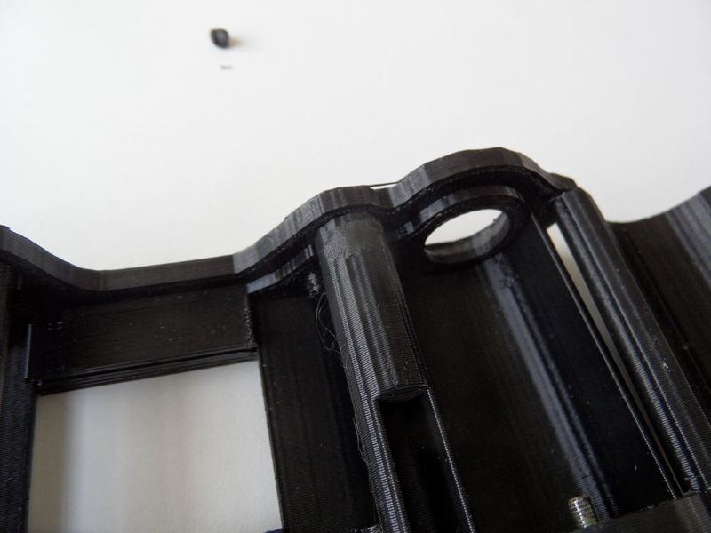
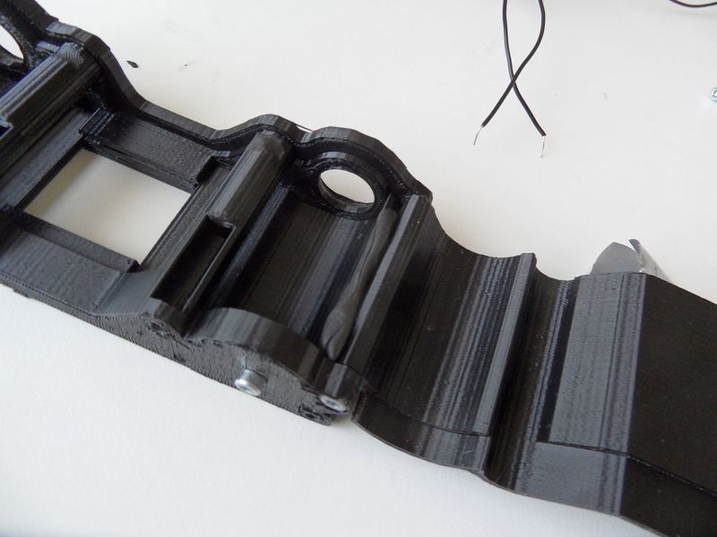
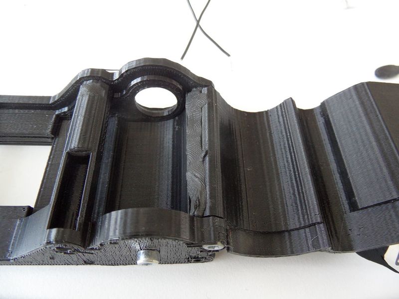
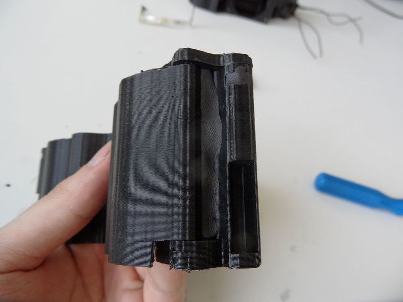
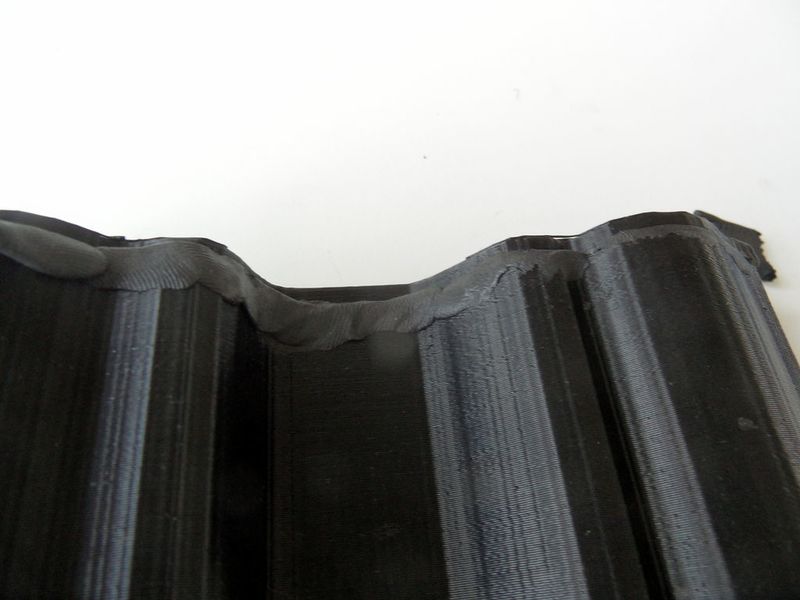
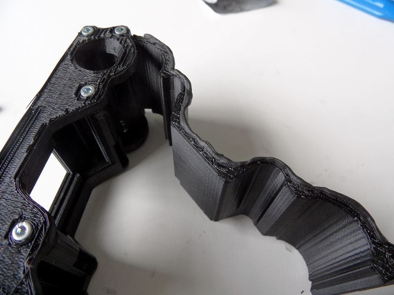
And now for some real lightproofing! The more sensitive part is the back, especially the BackCover border and around the screws columns.
If you put Sugru between two parts you need to be careful not to block them. They should still be able to move.
You can follow the picture to see how I did, you can add a bit more sugru under the Back-Body, under the screw columns and under the junctions with the BackCover, that's were most of the parasite light came from on my tests films.
Étape 15 - Assemble everything!
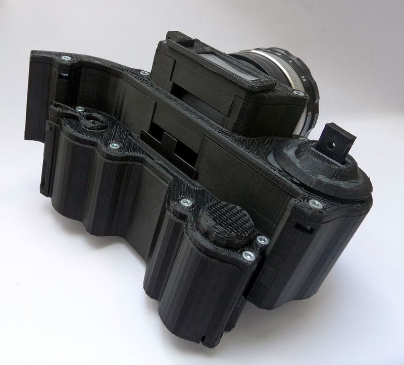
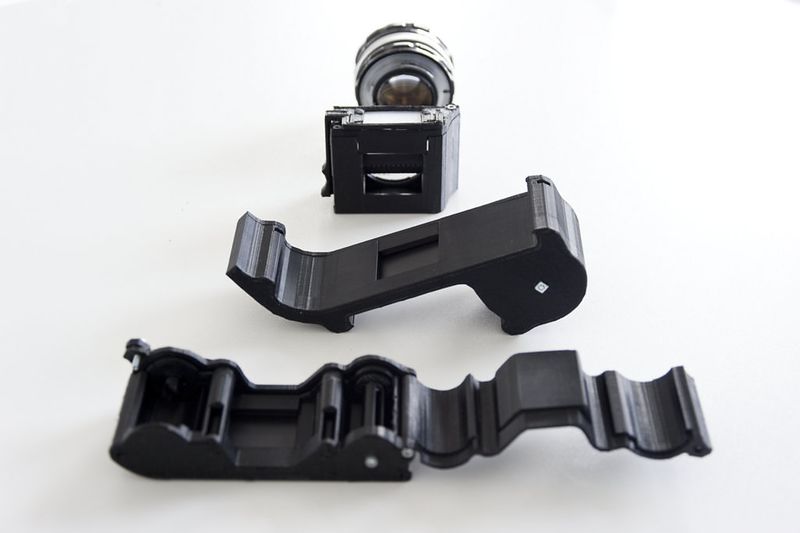
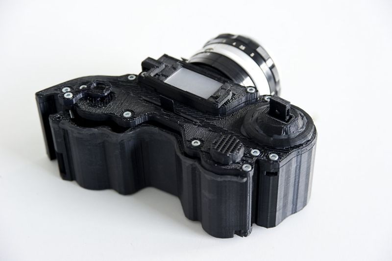
Once you got all the parts built separately it's time to assemble the camera! It's a very easy step, as everything snaps together!
All the parts should align at the bottom, and friction between part should be sufficient to keep them in place.
Sometime the covers block a bit, you can use strength or you you can just remove them and put them afterwards.
You can also add a bit of black Patafix [blue-tac] between the Back and the Shutter close to the exposed film area, their still are little lightproof issues here.
Your camera is finished! :)
Now let's see how it's working!
Étape 16 - Load film
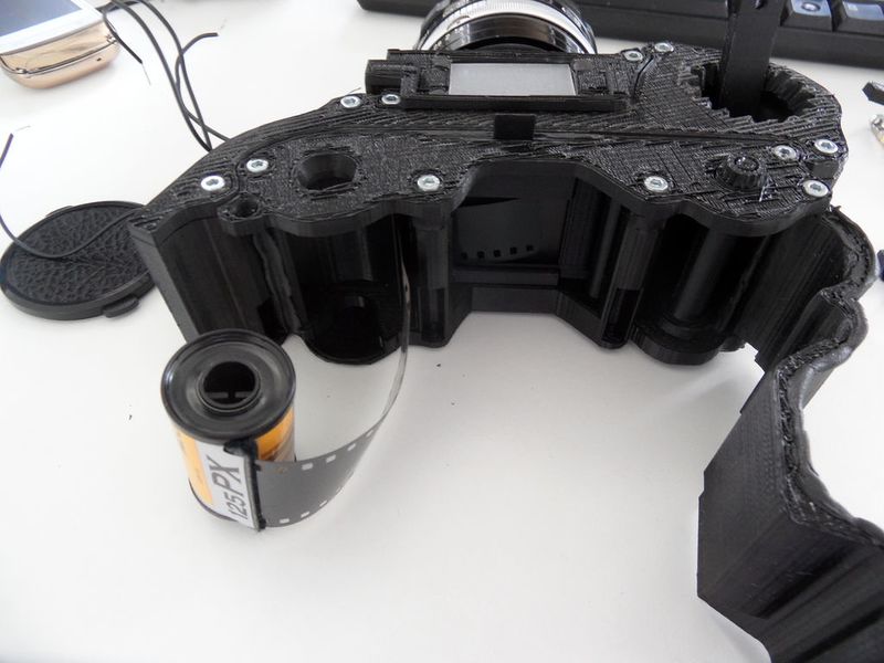
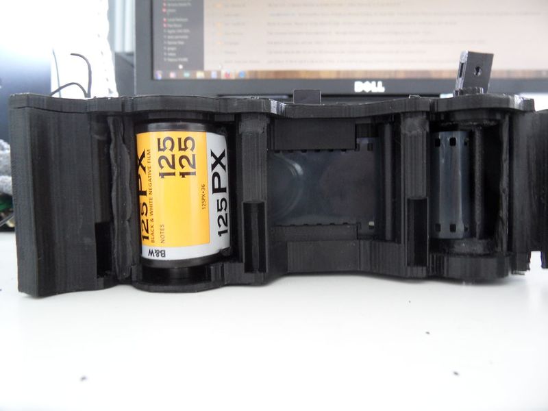
1- Open the Back by unscrewing the BackCover.
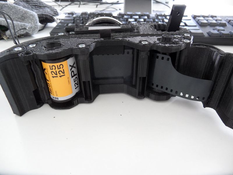
2- Set the film in place, unwell the film coil and slide it under the two FilmGuides and on the grove.
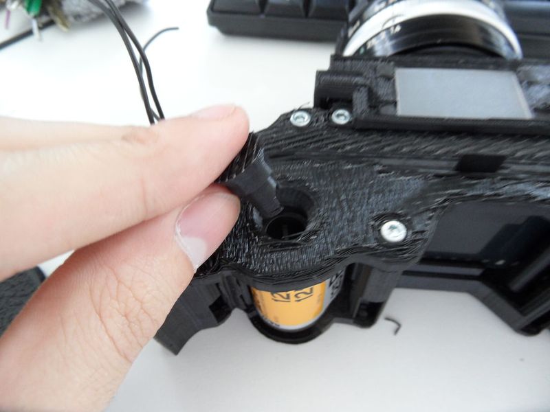
3- When the coil is in place you can put the Rewinder on, it should be driven by the coil.
4- Make the film pass in front of the Unwinder (you may use a pen or something to pull it), then pass some of it through the Unwinder. Make sure two holes of the film at least are taken in the teeth of the Unwinder.
5- Turn a bit the UnwinderButton to check that the film is correctly driven.
6- You can now close the BackCover, put the RewinderCover in place and screw it in. The Rewinder and the BackCover should be fixed.
Étape 17 - Take pictures!
Let's take pictures! Your film is loaded, your lens is on, everything should be ok!
If you want be accurate you'll need an exposure meter, set the settings with your film Iso and mode Exposure Time priority set to 1/60°s. If you haven't an exposure meter you can use a DSLR with the same settings. Look the aperture it advice and set the same on your lens.
There is ONLY 8 easy steps to take a picture:
1- Prepare your picture frame, with you lens at full aperture, look into the viewfinder to set the frame and the focus right. 2- Measure light and change the aperture of you lens by the optimal one. 3- Prime the shutter, pull on the ShutterActuator and set it in high position. 4- Lifts up the mirror using the MirrorAcuator. 5- Open the BackShutter by pulling it up. 6- Hold your breath and push quickly the ShutterActuator trying to not shake the camera too much due to emotion. 7- Close the BackShutter. 8- Turn the RewinderButton a bit for the next picture.
And start again for a new picture ! :)
This wikifab is over. Enjoy your new camera !
Notes et références
- Thanks to the ESADSE [ Superior School of Art and Design of Saint-Etienne (France) ] that trust me and support me on this project and allow me to bring it where this work on my studies time ! And also for their equipment, and their financial help. :)
- Thanks to my friends of the student associations Le_Garage and also to the RandomLab which help me on this project.
- Thanks to Yuki Suzuki who generously lent me one of his AP-Lens from the Japan.
- Thanks to La Fabrique d'Objets Libre (Lyon FabLab) for let me access to their tools.
- 95% of the 3D are made in the Open-source software Blender.
- The rest have been made with OpenScad.
- And 2D files have been made on Inkscape and OpenScad then cleaned in LibreCad.
- And I use MakerWare for slice my mesh for 3D printer. (I know... it's the only not open-source...)
- And finish by YOU : Thanks for reading, hope you like it and this gonna be useful ! :)
Draft Published

 Français
 English
 Deutsch
 Español
 Italiano
 Português