| (Une révision intermédiaire par un autre utilisateur non affichée) | |||
| Ligne 1 : | Ligne 1 : | ||
| − | {{ | + | {{Tuto Details |
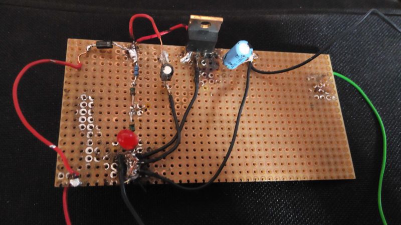
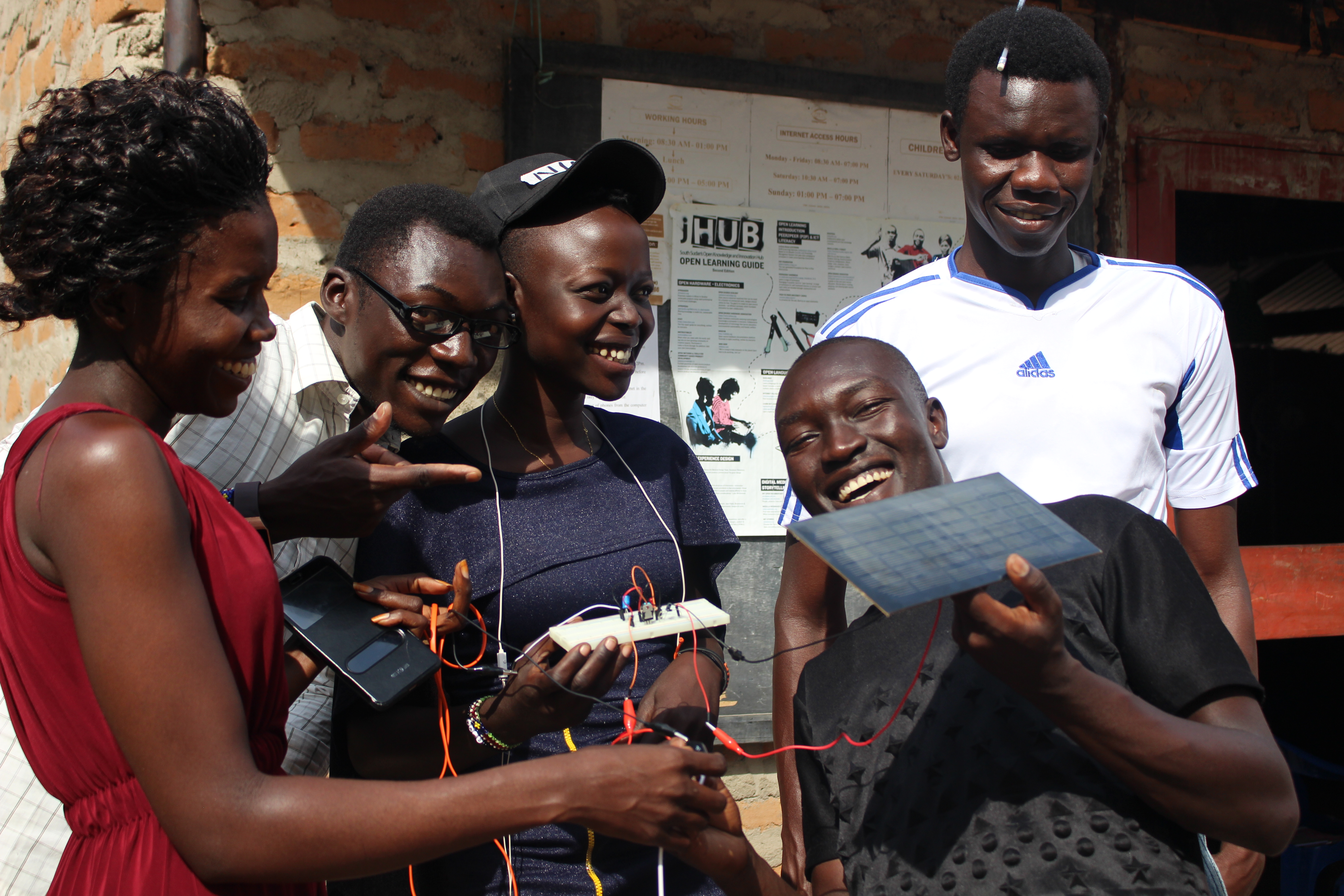
|Main_Picture=DIY_Solar_Charger_IMG_20181206_122839.jpg | |Main_Picture=DIY_Solar_Charger_IMG_20181206_122839.jpg | ||
| − | + | |Description=<translate>The solar charger</translate> | |
| − | |Description=The solar charger | ||
|Area=Electronics, Energy | |Area=Electronics, Energy | ||
|Type=Creation | |Type=Creation | ||
| Ligne 15 : | Ligne 14 : | ||
|IsTranslation=0 | |IsTranslation=0 | ||
}} | }} | ||
| − | {{ | + | {{Introduction |
| − | |Introduction= | + | |Introduction=<translate></translate> |
}} | }} | ||
| − | {{ | + | {{Materials |
|Step_Picture_00=DIY_Solar_Charger_IMG_8087.JPG | |Step_Picture_00=DIY_Solar_Charger_IMG_8087.JPG | ||
|Material=· Solar panel of (10v) optional | |Material=· Solar panel of (10v) optional | ||
| Ligne 55 : | Ligne 54 : | ||
· LED tester | · LED tester | ||
}} | }} | ||
| − | {{ | + | {{Tuto Step |
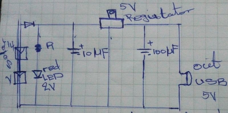
| − | + | |Step_Title=<translate>Drawing</translate> | |
| − | |Step_Title=Drawing | + | |Step_Content=<translate>Draw the diagram of the charger</translate> |
| − | |Step_Content=Draw the diagram of the charger | ||
|Step_Picture_00=DIY_Solar_Charger_IMG_20181206_192238.jpg | |Step_Picture_00=DIY_Solar_Charger_IMG_20181206_192238.jpg | ||
}} | }} | ||
| − | {{ | + | {{Tuto Step |
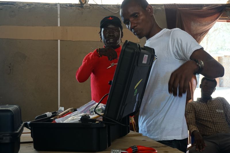
| − | |Step_Title=Asknet Box | + | |Step_Title=<translate>Asknet Box</translate> |
| − | |Step_Content= Open the [https://openculture.agency/outcomes/askotec/ ASKotec kit] and get the tools and materials to use | + | |Step_Content=<translate> Open the [https://openculture.agency/outcomes/askotec/ ASKotec kit] and get the tools and materials to use</translate> |
|Step_Picture_00=DIY_Solar_Charger_DSC00958.JPG | |Step_Picture_00=DIY_Solar_Charger_DSC00958.JPG | ||
}} | }} | ||
| − | {{ | + | {{Tuto Step |
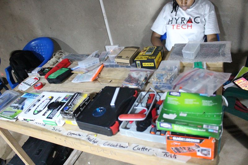
| − | |Step_Title=Tools and materials | + | |Step_Title=<translate>Tools and materials</translate> |
| − | |Step_Content=* Identify the tools and materials | + | |Step_Content=<translate>* Identify the tools and materials |
| − | * Arranged the materials and the tools | + | * Arranged the materials and the tools</translate> |
|Step_Picture_00=DIY_Solar_Charger_IMG_8194.JPG | |Step_Picture_00=DIY_Solar_Charger_IMG_8194.JPG | ||
}} | }} | ||
| − | {{ | + | {{Tuto Step |
| − | |Step_Title=Test the folllowing materials | + | |Step_Title=<translate>Test the folllowing materials</translate> |
| − | |Step_Content=* The total voltage of the solar panel | + | |Step_Content=<translate>* The total voltage of the solar panel |
| − | * The LED light using the LED tester | + | * The LED light using the LED tester</translate> |
}} | }} | ||
| − | {{ | + | {{Tuto Step |
| − | |Step_Title=Calculations | + | |Step_Title=<translate>Calculations</translate> |
| − | |Step_Content= Calculate the Resistance | + | |Step_Content=<translate> Calculate the Resistance</translate> |
}} | }} | ||
| − | {{ | + | {{Tuto Step |
| − | |Step_Title=Bread board | + | |Step_Title=<translate>Bread board</translate> |
| − | |Step_Content=Get the bread board and place it at the helping hand | + | |Step_Content=<translate>Get the bread board and place it at the helping hand</translate> |
}} | }} | ||
| − | {{ | + | {{Tuto Step |
| − | |Step_Title=Fix the following materials | + | |Step_Title=<translate>Fix the following materials</translate> |
| − | |Step_Content=* Fix a positive (+wire red in color) and negative (-wire black in color) for input source (power) | + | |Step_Content=<translate>* Fix a positive (+wire red in color) and negative (-wire black in color) for input source (power) |
* Fix the diode | * Fix the diode | ||
* Fix a positive wire from the input source (+wire) to the diode | * Fix a positive wire from the input source (+wire) to the diode | ||
| − | * Fix the resistors in positive side of the diode and have to be in series for easy calculation | + | * Fix the resistors in positive side of the diode and have to be in series for easy calculation</translate> |
}} | }} | ||
| − | {{ | + | {{Tuto Step |
| − | |Step_Title=Resistor | + | |Step_Title=<translate>Resistor</translate> |
| − | |Step_Content=Fix the resistors in positive side of the diode and have to be in series for easy calculation | + | |Step_Content=<translate>Fix the resistors in positive side of the diode and have to be in series for easy calculation</translate> |
}} | }} | ||
| − | {{ | + | {{Tuto Step |
| − | |Step_Title=LED light | + | |Step_Title=<translate>LED light</translate> |
| − | |Step_Content=Fix the LED light to positive side of the resistors | + | |Step_Content=<translate>Fix the LED light to positive side of the resistors</translate> |
}} | }} | ||
| − | {{ | + | {{Tuto Step |
| − | |Step_Title=Regulator | + | |Step_Title=<translate>Regulator</translate> |
| − | |Step_Content=Fix the regulator where the black side need to face your side | + | |Step_Content=<translate>Fix the regulator where the black side need to face your side</translate> |
}} | }} | ||
| − | {{ | + | {{Tuto Step |
| − | |Step_Title=Small Capacitor | + | |Step_Title=<translate>Small Capacitor</translate> |
| − | |Step_Content=Fix the small capacitor | + | |Step_Content=<translate>Fix the small capacitor</translate> |
}} | }} | ||
| − | {{ | + | {{Tuto Step |
| − | |Step_Title=Big capacitor | + | |Step_Title=<translate>Big capacitor</translate> |
| − | |Step_Content=Fix the big capacitor | + | |Step_Content=<translate>Fix the big capacitor</translate> |
}} | }} | ||
| − | {{ | + | {{Tuto Step |
| − | |Step_Title=Regulator and diode | + | |Step_Title=<translate>Regulator and diode</translate> |
| − | |Step_Content=Connect the left pin of the regulator to the diode and resistors | + | |Step_Content=<translate>Connect the left pin of the regulator to the diode and resistors</translate> |
}} | }} | ||
| − | {{ | + | {{Tuto Step |
| − | |Step_Title=capacitor, diode, resistor and regulator | + | |Step_Title=<translate>capacitor, diode, resistor and regulator</translate> |
| − | |Step_Content=Connect the positive pin of the first capacitor to the join the diode, resistors and the left pin of the regulator | + | |Step_Content=<translate>Connect the positive pin of the first capacitor to the join the diode, resistors and the left pin of the regulator</translate> |
}} | }} | ||
| − | {{ | + | {{Tuto Step |
| − | |Step_Title=Regulator and big capacitor | + | |Step_Title=<translate>Regulator and big capacitor</translate> |
| − | |Step_Content=Connect the right pin of the regulator to the positive pin of the big capacitor | + | |Step_Content=<translate>Connect the right pin of the regulator to the positive pin of the big capacitor</translate> |
}} | }} | ||
| − | {{ | + | {{Tuto Step |
| − | |Step_Title=Regulator and LED | + | |Step_Title=<translate>Regulator and LED</translate> |
| − | |Step_Content=Connect the middle pin of the regulator to the negative pin of the LED light | + | |Step_Content=<translate>Connect the middle pin of the regulator to the negative pin of the LED light</translate> |
}} | }} | ||
| − | {{ | + | {{Tuto Step |
| − | |Step_Title=Small capacitor to the LED | + | |Step_Title=<translate>Small capacitor to the LED</translate> |
| − | |Step_Content=Connect the negative pin of the small capacitor to negative pin of the LED light | + | |Step_Content=<translate>Connect the negative pin of the small capacitor to negative pin of the LED light</translate> |
}} | }} | ||
| − | {{ | + | {{Tuto Step |
| − | |Step_Title=Big capacitor and LED | + | |Step_Title=<translate>Big capacitor and LED</translate> |
| − | |Step_Content=Connect the negative pin of the big capacitor to negative pin of the LED light | + | |Step_Content=<translate>Connect the negative pin of the big capacitor to negative pin of the LED light</translate> |
}} | }} | ||
| − | {{ | + | {{Tuto Step |
| − | |Step_Title=All negative sides | + | |Step_Title=<translate>All negative sides</translate> |
| − | |Step_Content= In all connect the negative sides together | + | |Step_Content=<translate> In all connect the negative sides together</translate> |
}} | }} | ||
| − | {{ | + | {{Tuto Step |
| − | |Step_Title=Positive wire | + | |Step_Title=<translate>Positive wire</translate> |
| − | |Step_Content=Fix +wire to the positive pin of the big capacitor | + | |Step_Content=<translate>Fix +wire to the positive pin of the big capacitor</translate> |
}} | }} | ||
| − | {{ | + | {{Tuto Step |
| − | |Step_Title=Negative | + | |Step_Title=<translate>Negative</translate> |
| − | |Step_Content=Fix –wire to the negative pin of the big capacitor | + | |Step_Content=<translate>Fix –wire to the negative pin of the big capacitor</translate> |
}} | }} | ||
| − | {{ | + | {{Tuto Step |
| − | |Step_Title=Female USB | + | |Step_Title=<translate>Female USB</translate> |
| − | |Step_Content=Connect the female USB to the +wire and –wire on the capacitor | + | |Step_Content=<translate>Connect the female USB to the +wire and –wire on the capacitor</translate> |
}} | }} | ||
| − | {{ | + | {{Tuto Step |
| − | |Step_Title=Test | + | |Step_Title=<translate>Test</translate> |
| − | |Step_Content=Test the solar charger in the sun and test the output and charge the phone | + | |Step_Content=<translate>Test the solar charger in the sun and test the output and charge the phone</translate> |
}} | }} | ||
| − | {{ | + | {{Notes |
| − | |Notes= | + | |Notes=<translate></translate> |
}} | }} | ||
| − | {{ | + | {{PageLang |
| − | |||
}} | }} | ||
| + | {{Tuto Status | ||
| + | |Complete=Published | ||
| + | }} | ||
| + | {{Separator}} | ||
Version actuelle datée du 4 juillet 2023 à 18:21
Sommaire
- 1 Étape 1 - Drawing
- 2 Étape 2 - Asknet Box
- 3 Étape 3 - Tools and materials
- 4 Étape 4 - Test the folllowing materials
- 5 Étape 5 - Calculations
- 6 Étape 6 - Bread board
- 7 Étape 7 - Fix the following materials
- 8 Étape 8 - Resistor
- 9 Étape 9 - LED light
- 10 Étape 10 - Regulator
- 11 Étape 11 - Small Capacitor
- 12 Étape 12 - Big capacitor
- 13 Étape 13 - Regulator and diode
- 14 Étape 14 - capacitor, diode, resistor and regulator
- 15 Étape 15 - Regulator and big capacitor
- 16 Étape 16 - Regulator and LED
- 17 Étape 17 - Small capacitor to the LED
- 18 Étape 18 - Big capacitor and LED
- 19 Étape 19 - All negative sides
- 20 Étape 20 - Positive wire
- 21 Étape 21 - Negative
- 22 Étape 22 - Female USB
- 23 Étape 23 - Test
- 24 Commentaires
Matériaux
· Solar panel of (10v) optional
· Diode
· Resistors
· Regulator(5MA-20AM)
· Capacitors of (10-100)
· LED light of(2v or 3v)
· Jumper wire
· Circuit board
· Bread board
Outils
· Wires(red and black)
· Soldering iron
· Soldering wire
· Soldering grease
· Helping hand
· Sucker
· Scissor
· Multimeter
· LED tester
Étape 4 - Test the folllowing materials
- The total voltage of the solar panel
- The LED light using the LED tester
Étape 5 - Calculations
Calculate the Resistance
Étape 6 - Bread board
Get the bread board and place it at the helping hand
Étape 7 - Fix the following materials
- Fix a positive (+wire red in color) and negative (-wire black in color) for input source (power)
- Fix the diode
- Fix a positive wire from the input source (+wire) to the diode
- Fix the resistors in positive side of the diode and have to be in series for easy calculation
Étape 8 - Resistor
Fix the resistors in positive side of the diode and have to be in series for easy calculation
Étape 9 - LED light
Fix the LED light to positive side of the resistors
Étape 10 - Regulator
Fix the regulator where the black side need to face your side
Étape 11 - Small Capacitor
Fix the small capacitor
Étape 12 - Big capacitor
Fix the big capacitor
Étape 13 - Regulator and diode
Connect the left pin of the regulator to the diode and resistors
Étape 14 - capacitor, diode, resistor and regulator
Connect the positive pin of the first capacitor to the join the diode, resistors and the left pin of the regulator
Étape 15 - Regulator and big capacitor
Connect the right pin of the regulator to the positive pin of the big capacitor
Étape 16 - Regulator and LED
Connect the middle pin of the regulator to the negative pin of the LED light
Étape 17 - Small capacitor to the LED
Connect the negative pin of the small capacitor to negative pin of the LED light
Étape 18 - Big capacitor and LED
Connect the negative pin of the big capacitor to negative pin of the LED light
Étape 19 - All negative sides
In all connect the negative sides together
Étape 20 - Positive wire
Fix +wire to the positive pin of the big capacitor
Étape 21 - Negative
Fix –wire to the negative pin of the big capacitor
Étape 22 - Female USB
Connect the female USB to the +wire and –wire on the capacitor
Étape 23 - Test
Test the solar charger in the sun and test the output and charge the phone
Published
 Français
 English
 Deutsch
 Español
 Italiano
 Português