Sommaire
- 1 Introduction
- 2 Étape 1 - About building this machine
- 3 Étape 2 - Thread the aluminum profiles
- 4 Étape 3 - Prepare the aluminum strips and T-bars
- 5 Étape 4 - Assemble the structural bars
- 6 Étape 5 - Bend the paperclips
- 7 Étape 6 - Prepare the wooden strips
- 8 Étape 7 - Assemble the comb
- 9 Étape 8 - Prepare the acrylic parts
- 10 Étape 9 - Prepare layer (A)2
- 11 Étape 10 - Assemble the acrylic layers - 1/2
- 12 Étape 11 - Assemble the acrylic layers - 2/2
- 13 Étape 12 - Attach the T-shaped bar
- 14 Étape 13 - Align '2020nuts' with holes in acrylic
- 15 Étape 14 - Fix the acrylic on top of the structural bar
- 16 Étape 15 - Placing the 'encoder rack'
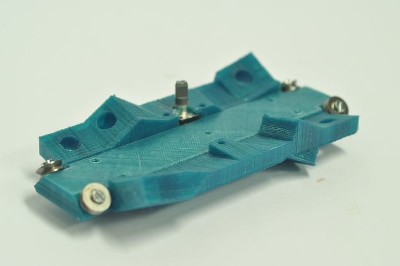
- 17 Étape 16 - Assemble the “top_plate_bearings” part
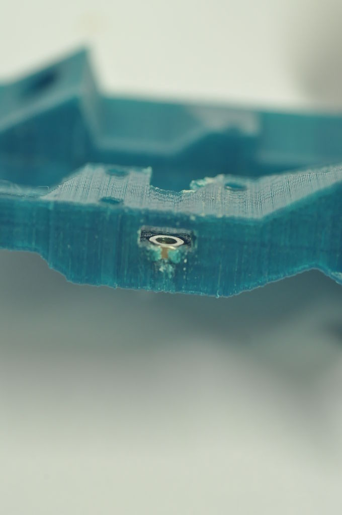
- 18 Étape 17 - Prepare the top of the carriage part
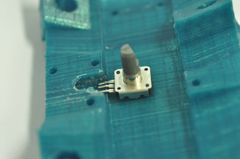
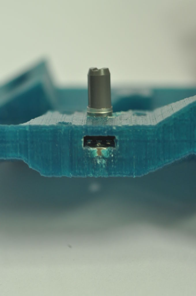
- 19 Étape 18 - Place the rotary encoder
- 20 Étape 19 - Assemble “top_plate_bearings” part with “top_plate” part
- 21 Étape 20 - Add the gear
- 22 Étape 21 - Prepare a servomotor
- 23 Étape 22 - Place the servo on the top plate
- 24 Étape 23 - Prepare the main carriage
- 25 Étape 24 - Add another bearing
- 26 Étape 25 - Place “servo_mount_carriage” parts
- 27 Étape 26 - Prepare the servo motor
- 28 Étape 27 - Make the 'servo beam mount'
- 29 Étape 28 - Attach the motor to the carriage
- 30 Étape 29 - Assemble the slider part
- 31 Étape 30 - Prepare the SLED mechanism
- 32 Étape 31 - Attach the motor
- 33 Étape 32 - Add arms
- 34 Étape 33 - Almost done with the carriage...
- 35 Étape 34 - Make the 'legs' of the machine
- 36 Étape 35 - Place the 3030 profiles
- 37 Étape 36 - Place the short aluminum profiles
- 38 Étape 37 - Place the vertical short bars
- 39 Étape 38 - Prepare the yarn carrier
- 40 Étape 39 - Bring the yarn carrier in position
- 41 Étape 40 - Place the 'L_2020-3030' parts
- 42 Étape 41 - Bring the encoder rack into position
- 43 Étape 42 - Place the carriages
- 44 Étape 43 - Place the top carriage
- 45 Étape 44 - Place nuts for the rods
- 46 Étape 45 - Place the rods
- 47 Étape 46 - Place nuts on top of the rods
- 48 Étape 47 - Insert the 'teeth'
- 49 Étape 48 - Prepare the bearing for the motor
- 50 Étape 49 - Assemble the stepper motor holder
- 51 Étape 50 - Place the stepper motor
- 52 Étape 51 - Attach the back side of the motor.
- 53 Étape 52 - Attach the Arduino
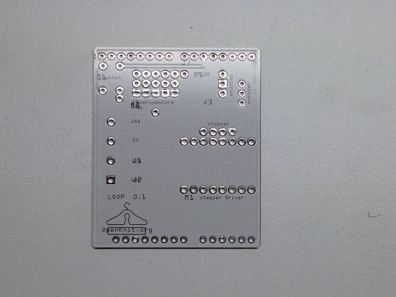
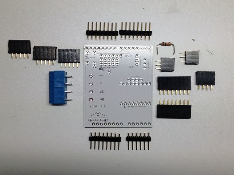
- 54 Étape 53 - Build the Arduino shield
- 55 Étape 54 - Place the Arduino shield
- 56 Étape 55 - Connect the Arduino shield
- 57 Étape 56 - Prepare the tensor - side 1
- 58 Étape 57 - Prepare the tensor - side 2
- 59 Étape 58 - Prepare the paraffin block
- 60 Étape 59 - Clamp the paraffin block
- 61 Étape 60 - Thread the machine - part 1
- 62 Étape 61 - Thread the machine - part 1
- 63 Étape 62 - Thread the machine - part 2
- 64 Étape 63 - Thread the machine - part 2
- 65 Étape 64 - Wiring the motors
- 66 Étape 65 - Connecting the power supply
- 67 Étape 66 - Organizing the wires
- 68 Étape 67 - Calibrating the servo motors
- 69 Étape 68 - Running the code for knitting
- 70 Étape 69 - Preparing for knitting
- 71 Étape 70 - Knitting
- 72 Commentaires
Introduction
Matériaux
Bill of materials (updates) available here.
- Two 800x3 mm aluminum strips
- Two 800x2 mm aluminum strips
- Two 30x30x162 mm aluminum bars
- Two 30x30x300 mm aluminum bars
- Two 20x20x800 mm aluminum bars
- Two 30x30x800 mm aluminum bars
- Two 15x15x800 mm aluminum T-profile
- One Arduino Leonardo
- One micro interruptor
- One rotary encoder
- One axial bearing
- One stepper motor
- One timing pulley
- Six threaded rods, sizes: 2x16 2x17 and 2x22 mm
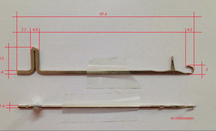
- 120 Knitmaster empisal silver knitting machine needles
- Four servo motors
- Four servo motor driver
- One timing belt
- 16 v-groove bearings
- One block of paraffine
- One bag Molex c-grid plastic holders: 4-pin, 3-pin and 2-pin
- One bag Molex c-grid female pins
- Phone cable on a reel (5 meter minimum)
- 120 paperclips 32 mm type N.2
- One piano hinge 510 mm
- Two wooden strips: flat on one side, a hole every 60 mm
- One rass rod 1.5 mm
- A bag of pin headers, male and female
- One terminal block
- One switching power supply
- One cross-shaped bead
Bolts and nuts, in generous amounts
- M3 tapered 7 mm
- M3 tapered 10 mm
- M3 tapered 12 mm
- M3 tapered 16 mm
- M3 tapered 20 mm
- M3 tapered 30 mm
- M3 flat head 8 mm
- M3 flat head 10 mm
- M3 flat head 12 mm
- M3 flat head 16 mm
- M3 flat head 20 mm
- M3 flat head 30 mm
- M3 regular nuts
- M3 nylock
- M3 washers
- M8 nuts and bolts (only a few)
- M8 washers (only a few)
Outils
flat screwdriver medium size phillips screwdriver medium size allen key M3 pliers tweezers wrench M6 and M8 small flat file small circular file hammer small zip ties grease lubricant spray or liquid lubricant
Étape 1 - About building this machine
The process from start to scarf can be divided in three steps:
- building the machine
- connecting the machine
- using the machine
This wikifab shows you all the steps to build the structural part of the machine.
Étape 2 - Thread the aluminum profiles
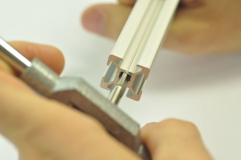
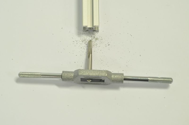
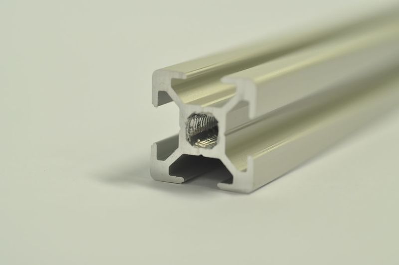
You'll need to thread:
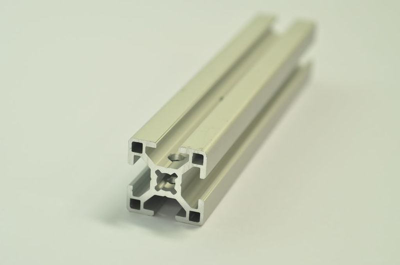
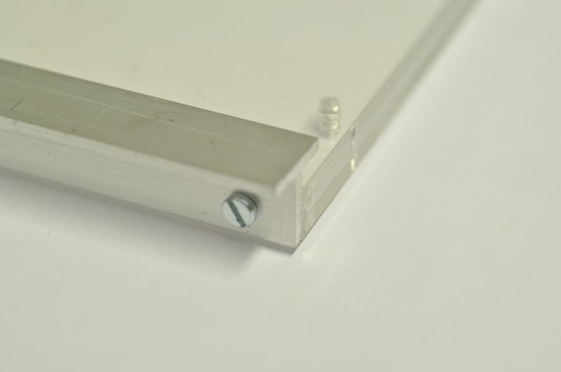
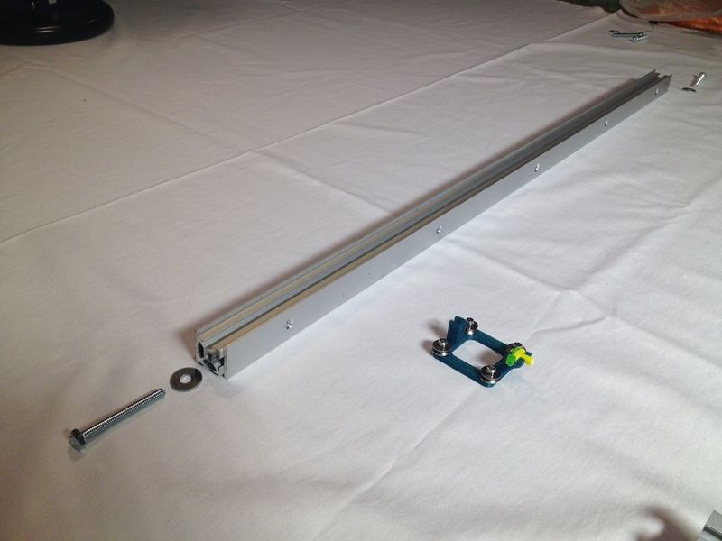
two 20x20x800 mm bars: 6 mm tool on both sides. two 30x30x800 mm bars: 8 mm tool on both sides. two 30x30x162 mm bars: 8 mm tool on ONE side, plus one 8 mm hole on the top (see image).
Étape 3 - Prepare the aluminum strips and T-bars
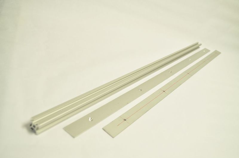
Make holes, and sink them with a countersink tool so the bolts will not stick out.
Flat strips
Make a hole at 50, 225, 400, 575, 750 mm.
(this doesn’t have to be very precise)
T-shaped bar:
Make holes at 14, 142, 271, 392, 410, 529, 657, 787 mm.
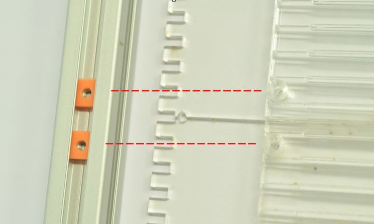
Place profile next to the acrylic to mark the exact place where the holes are going to be, this MUST be precise.
Étape 4 - Assemble the structural bars
You need:
- 20 x 20 profiles
- 20 mm aluminum strips
- 3D printed squares (8x8 mm): '2020 nuts'
- threaded nuts
- M3 x 7 bolts
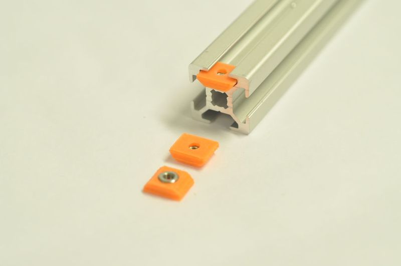
Prepare the 2020 nuts: You need the 3D printed squares (8x8 mm) and threaded nuts, five per strip. Place the nuts into the 3D printed parts.
Slide the nuts into the profile bar
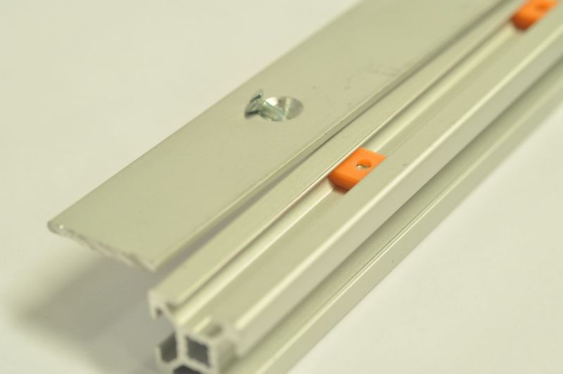
See picture. Align the nuts with the holes in the aluminum strip.
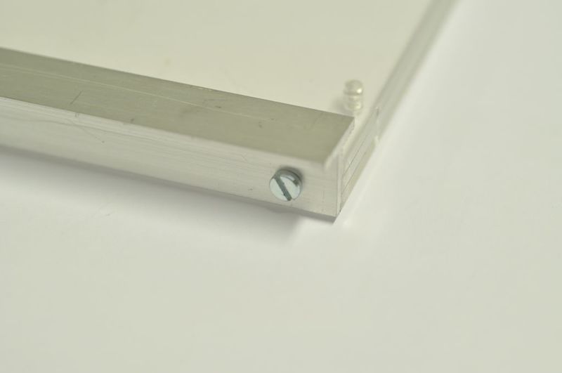
Close the top of the bar
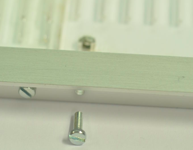
Using the M3 bolts.
Repeat on the bottom
Slide in five 2020 nuts, close the assembly with an aluminum strip.
Repeat this procedure with the other 2020 profile bar
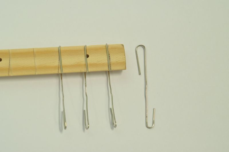
Étape 5 - Bend the paperclips
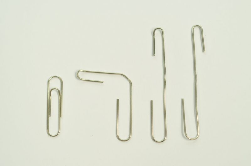
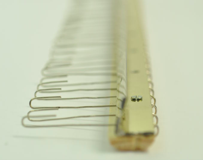
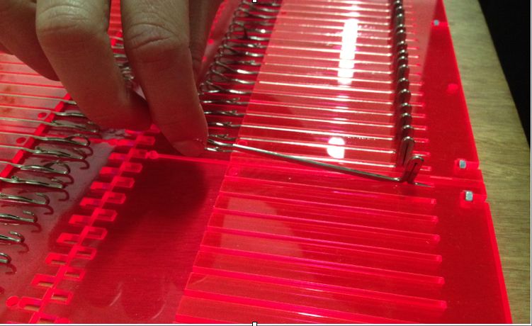
Bend the paperclips as indicated in the image. The 'hook' on the right is the end result. You'll need 60 of them, have fun bending!
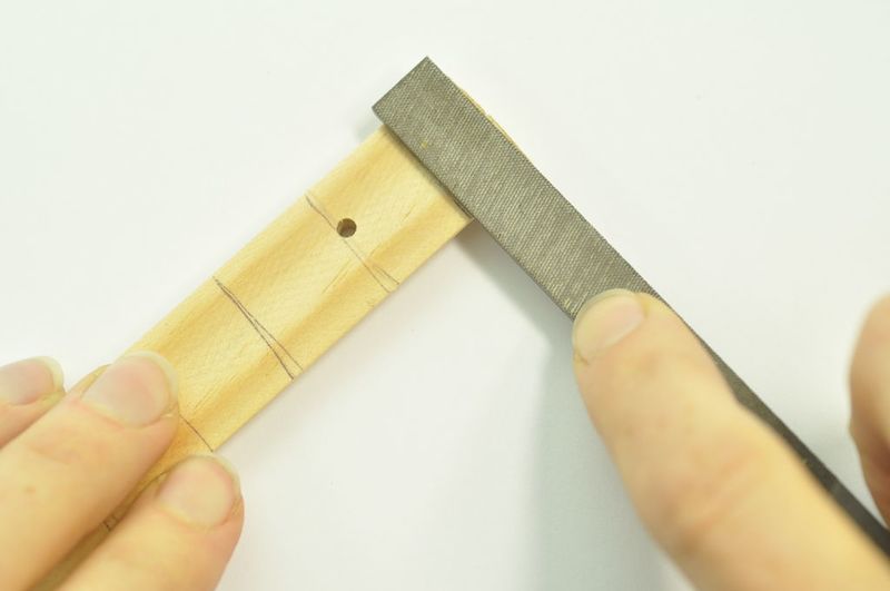
Étape 6 - Prepare the wooden strips
The wooden strips will be part of the comb. For this part you need:
- Two half -rounded wooden strips, a hole every 60 mm and lines every 15 mm
- 60 paperclips
- Long flat hinge
- M3 bolts and nuts, 12 mm
Preparation:
- File small slide at the indicated lines.
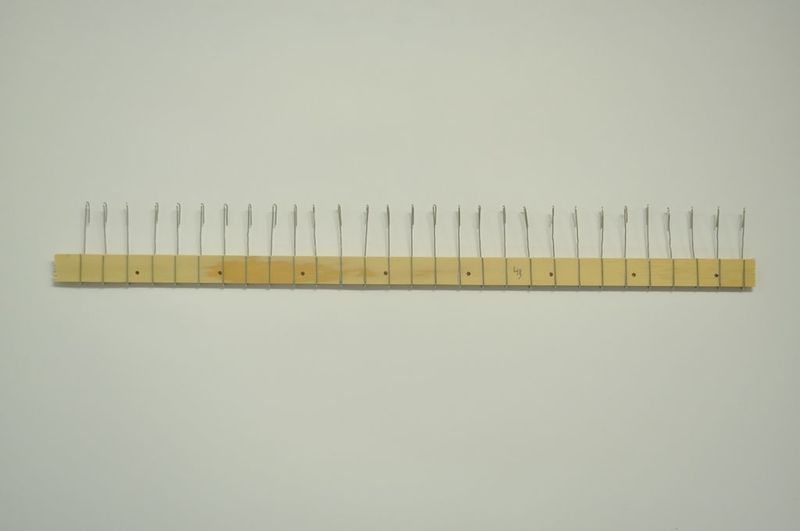
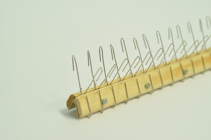
- Place the clips inside the slids. 30 per bar.
- Take a look at the pictures how to position the 'hooks'.
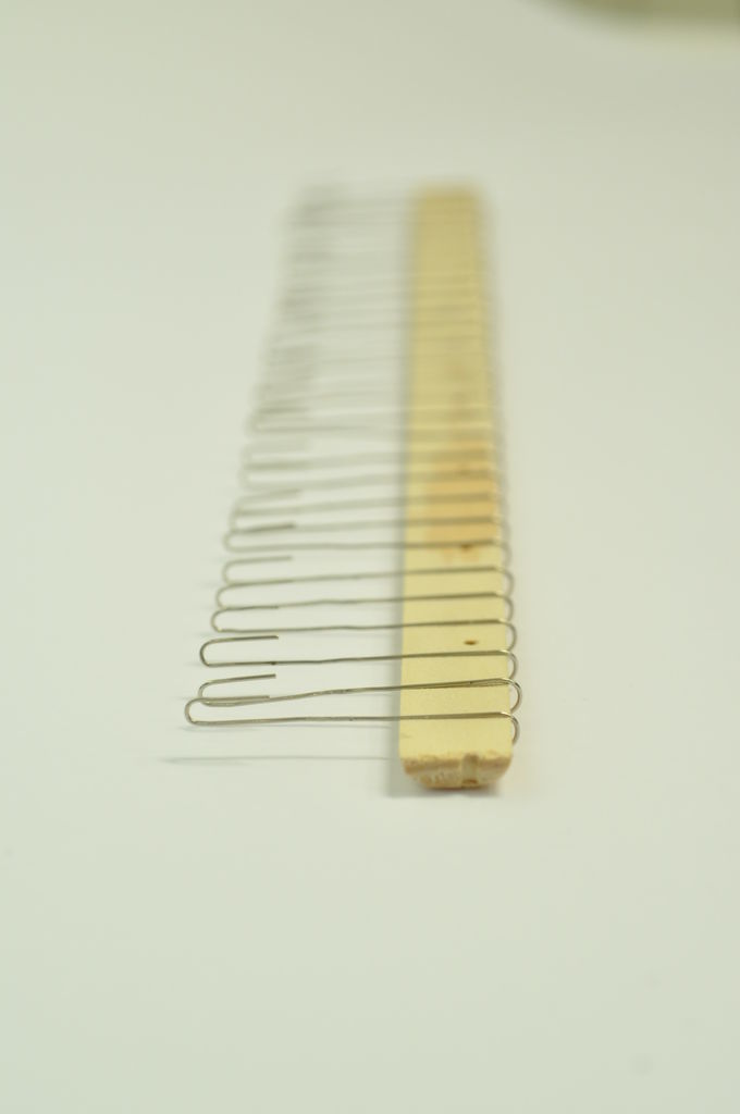
Étape 7 - Assemble the comb
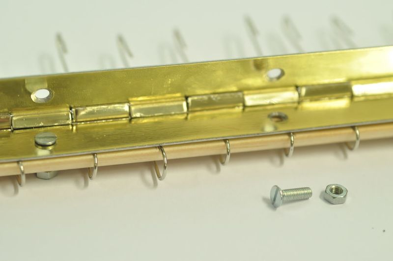
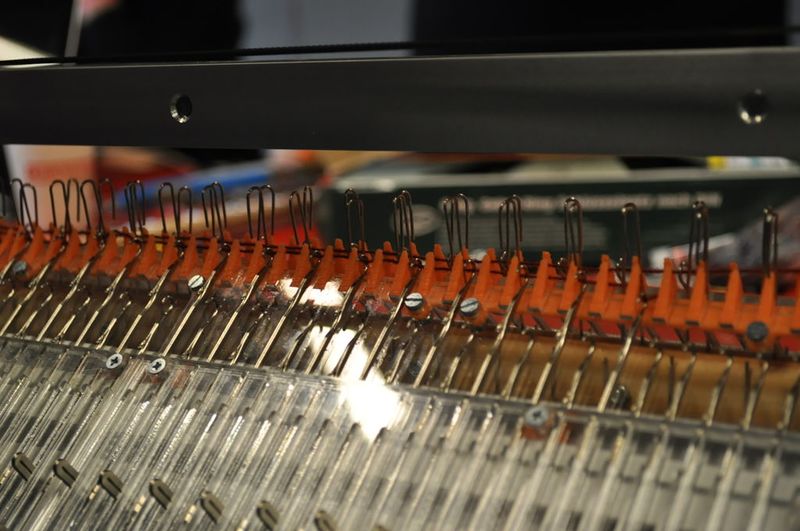
Attach the hinge to the flat sides of the wooden pieces as indicated in the images. When the hinge opens, the hooks cross each other.
Étape 8 - Prepare the acrylic parts
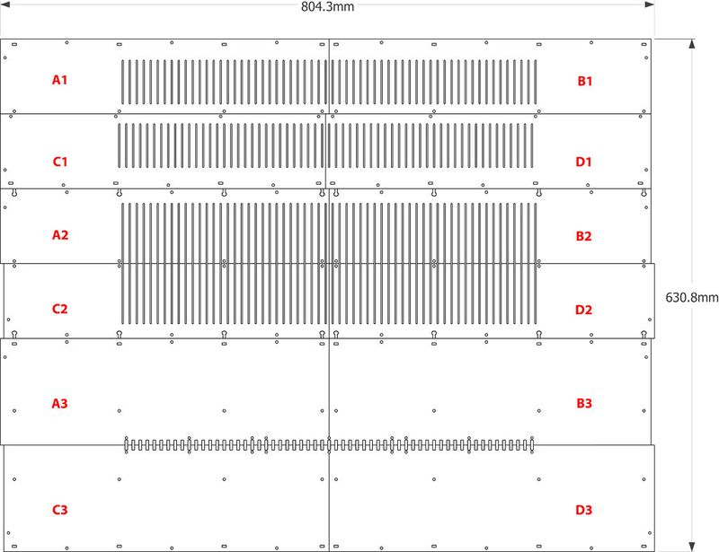
Place the acrylic parts in front of you on a table as indicated.
Make four piles of three layers each: see following step.
Étape 9 - Prepare layer (A)2
Start with pile A. Take layer A1 off
In layer A2, sink three holes, indicated in RED. Then later, the bolts will not stick out.
Étape 10 - Assemble the acrylic layers - 1/2
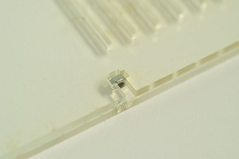
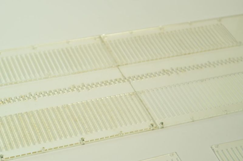
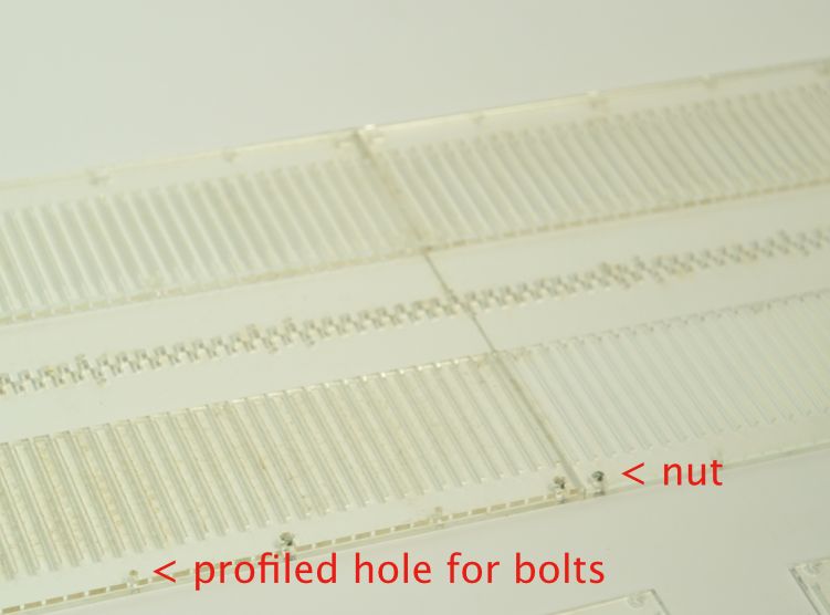
Place nuts into the 4 pockets in A2.
Place 120 needles in the openings.
Repeat for pile B, C and D.
Étape 11 - Assemble the acrylic layers - 2/2
Place layers (A, B, C, D )1 back on top, get 8 rounded bolts M3 x 12.
Screw the layers together.
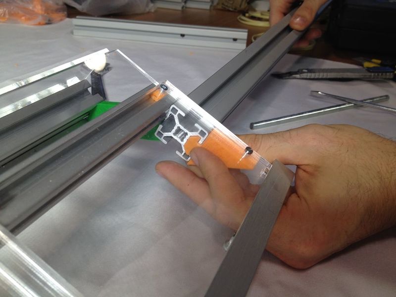
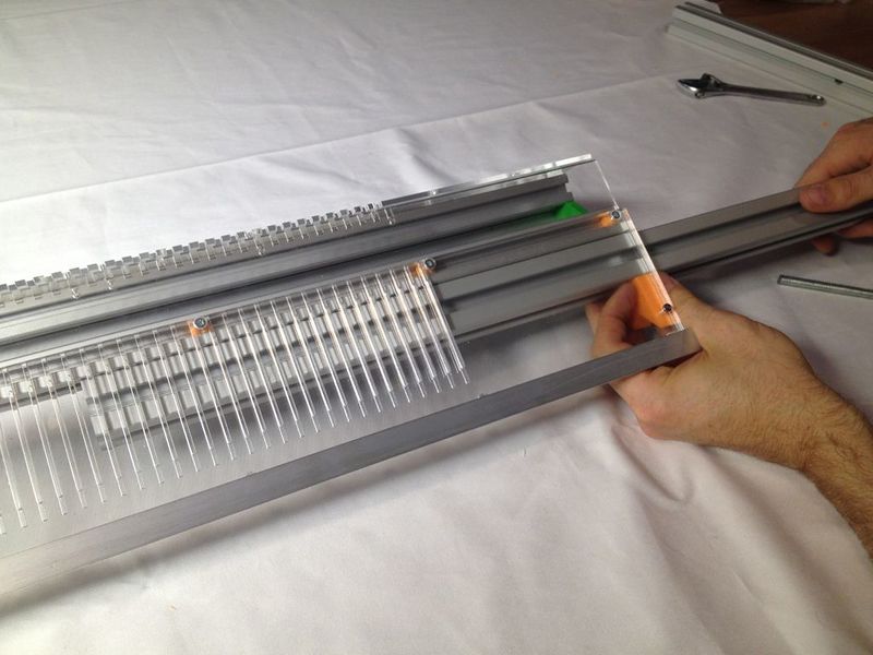
Étape 12 - Attach the T-shaped bar
Attach the T-shape profile to the bottoms of A 1-3 and B1-3.
First loosely, if it al fits thighten all bolts.
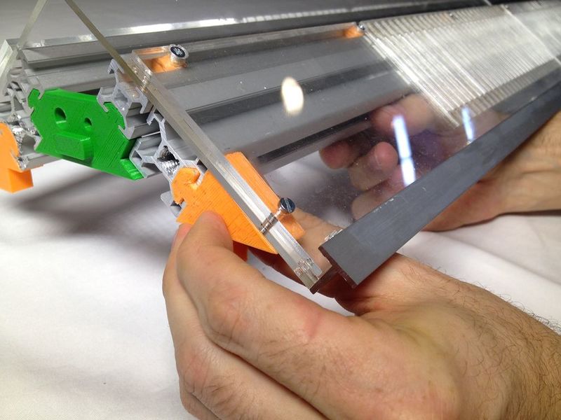
Étape 14 - Fix the acrylic on top of the structural bar
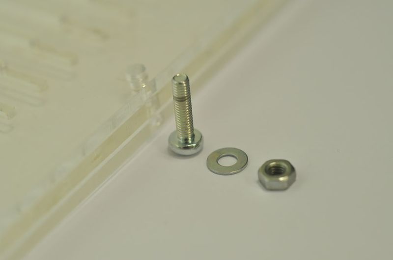
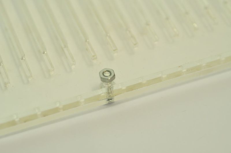
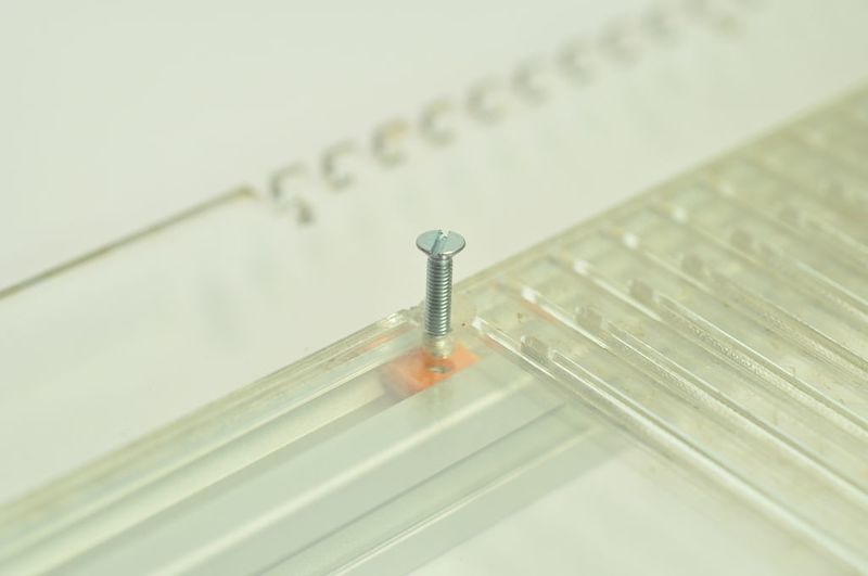
Sink holes, and place bolts & nuts through acrylic into the nuts.
Use 8 x M3x14 countersink bolts.
Also fix piles B, C and D to the T shape and structural bar.
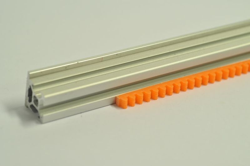
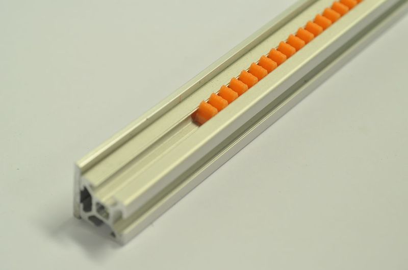
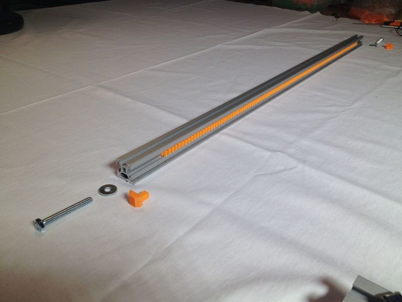
Étape 15 - Placing the 'encoder rack'
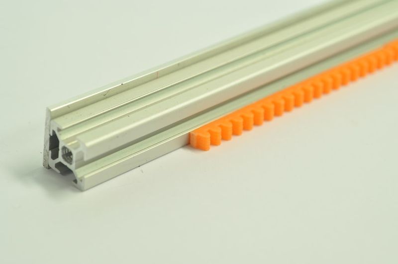
First place the ‘encoder_rack’ pieces along the bar.
Leave 50 mm on each side.
Press the piece into the bar.
Étape 16 - Assemble the “top_plate_bearings” part
Take the “top_plate_bearings” part + 4 bearings and attach them as indicated.
Étape 17 - Prepare the top of the carriage part
Take the “top_plate” part.
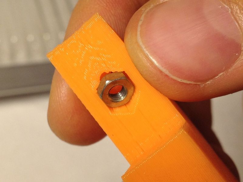
Place a nut into the hole.
Catch the nut with the screw.
Pull the nut down, take screw out.
Now the nut is 'seeded'.
Étape 18 - Place the rotary encoder
Place the rotary encoder with the pins straight, cut the legs.
Slide it in, careful with the pins.
Étape 19 - Assemble “top_plate_bearings” part with “top_plate” part
Take five long M3x12 countersink bolts.
Attach the two parts firmly.
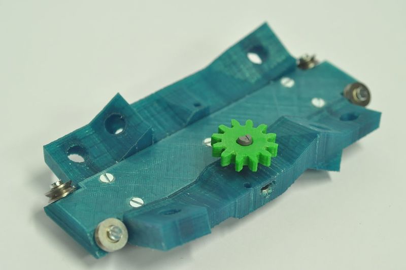
Étape 20 - Add the gear
Once the screws are all attached, place the “encoder_pinion” on the rotary encoder.
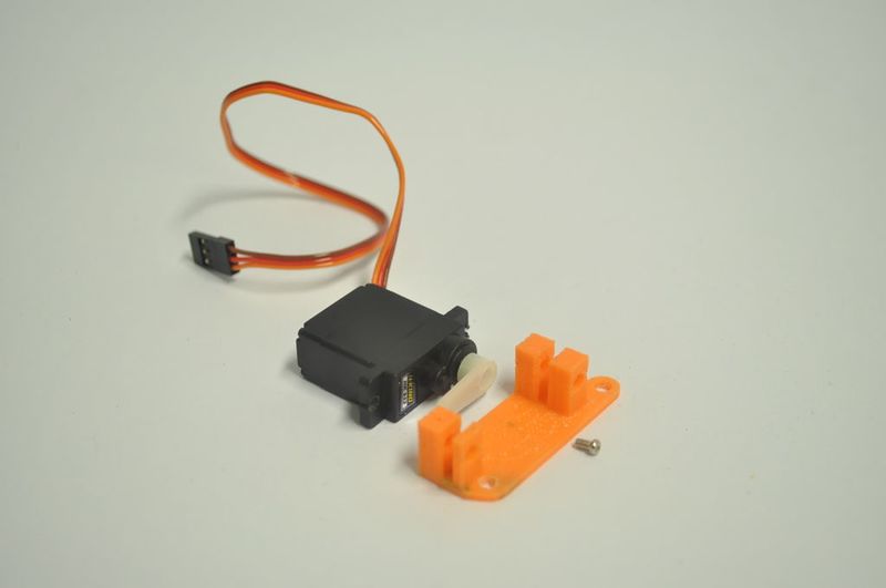
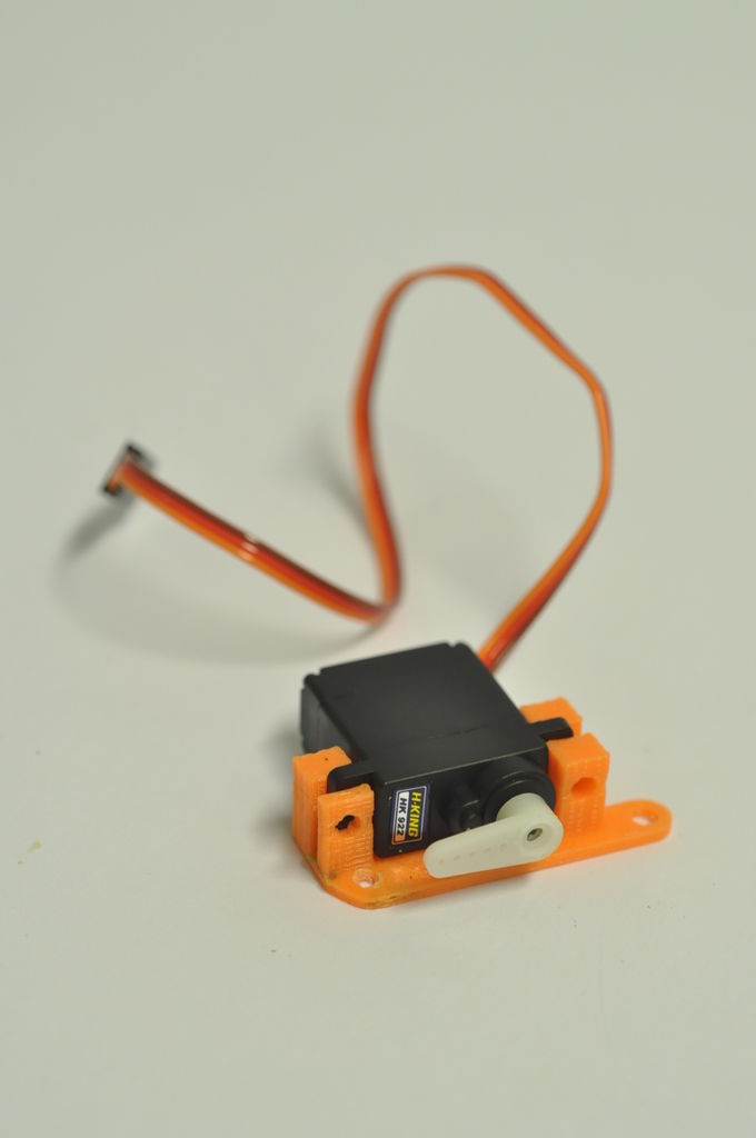
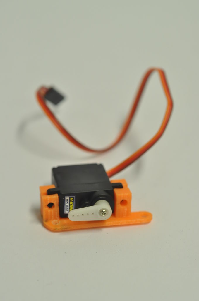
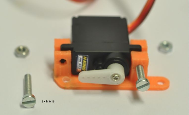
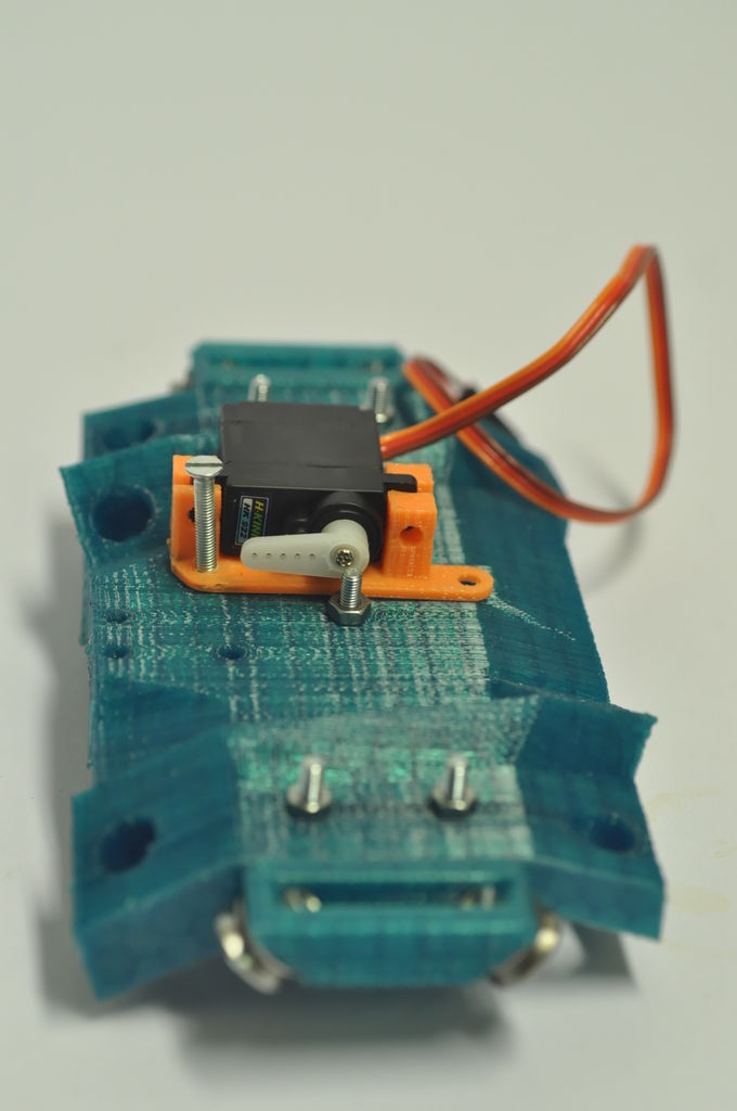
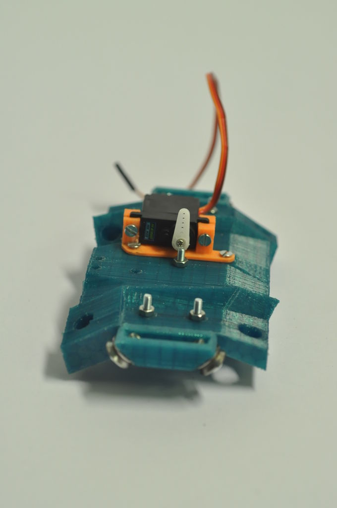
Étape 21 - Prepare a servomotor
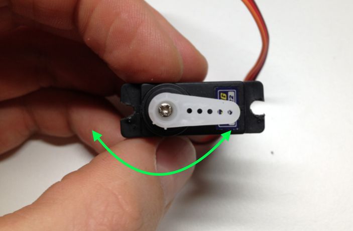
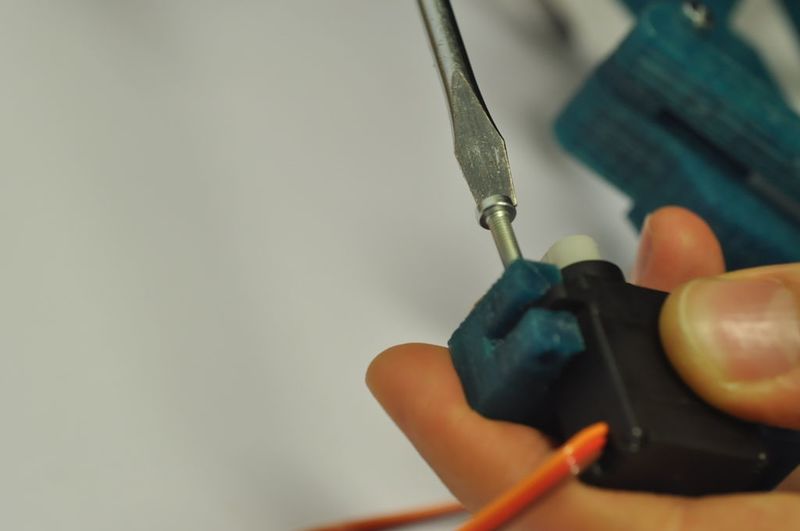
Use the “top_plate_servo_mount”, place the servo in - be careful not to loose the tiny servo bolt that comes with the motor.
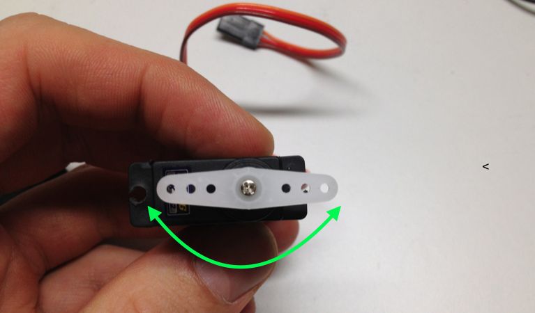
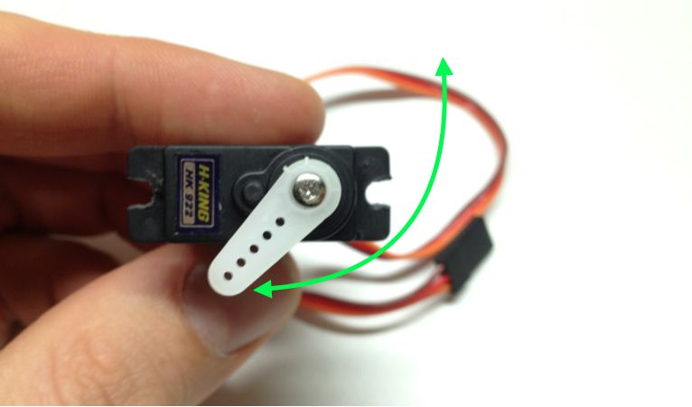
Make sure the arm does the movement indicated in green.
Attach the tiny screw.
Put M3 x 16 bolts through holder and motor to fixate them.
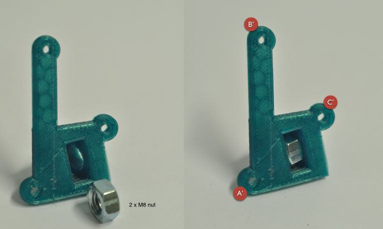
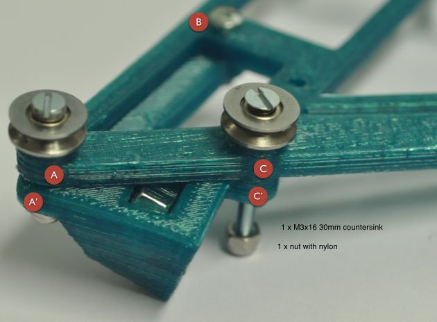
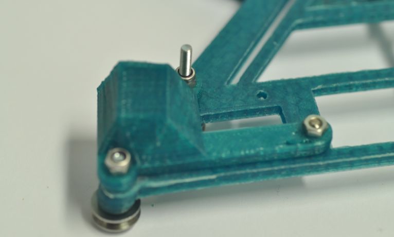
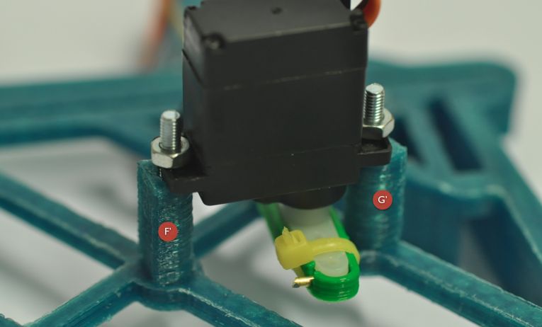
Étape 23 - Prepare the main carriage
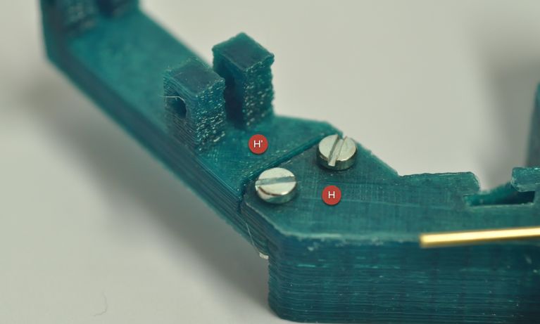
These are the parts you need.
Each hole corresponds to a letter.
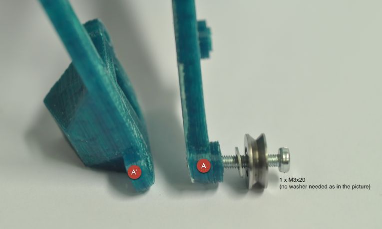
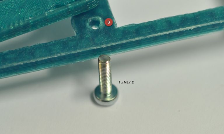
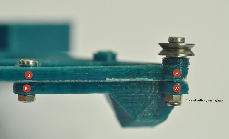
Étape 24 - Add another bearing
Use M3x16 30mm countersink bolt and nylock nut to attach the bearing.
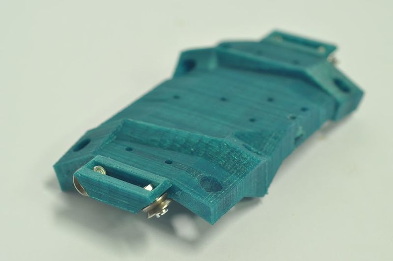
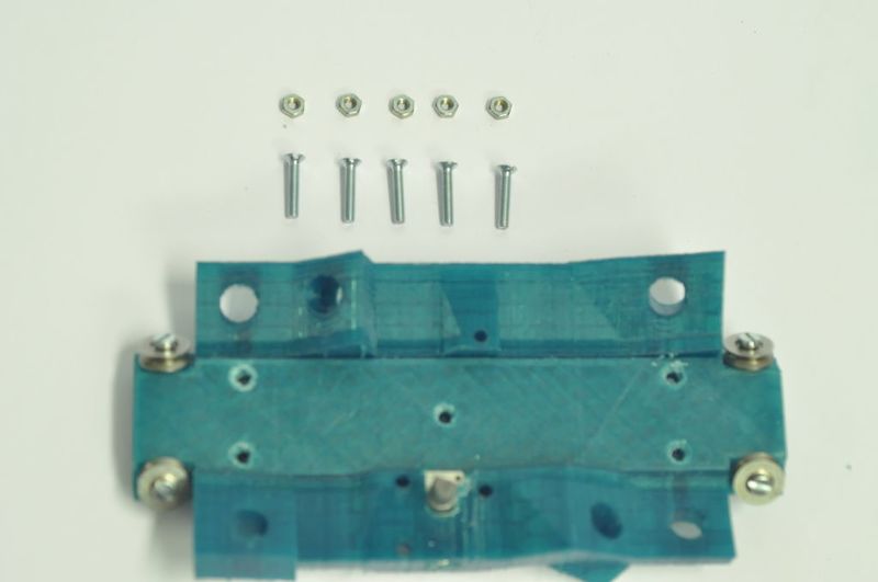
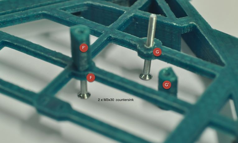
Étape 25 - Place “servo_mount_carriage” parts
You'll need 2 x M3x30 countersink bolts to place the servo mount carriage parts.
Étape 26 - Prepare the servo motor
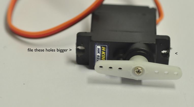
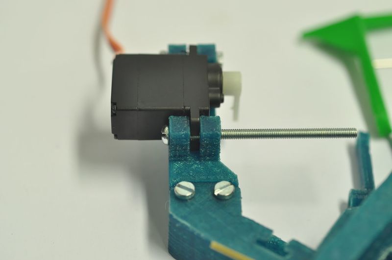
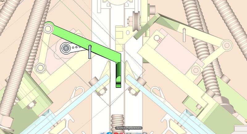
Position the ‘wings’ of the servo motor like this and fix with the tiny screw from the package. File its holes on both sides of the black plastic, they need to be a bit wider. Make sure the arm moves as indicated in green.
Étape 27 - Make the 'servo beam mount'
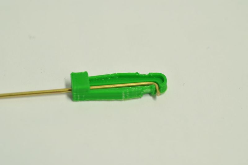
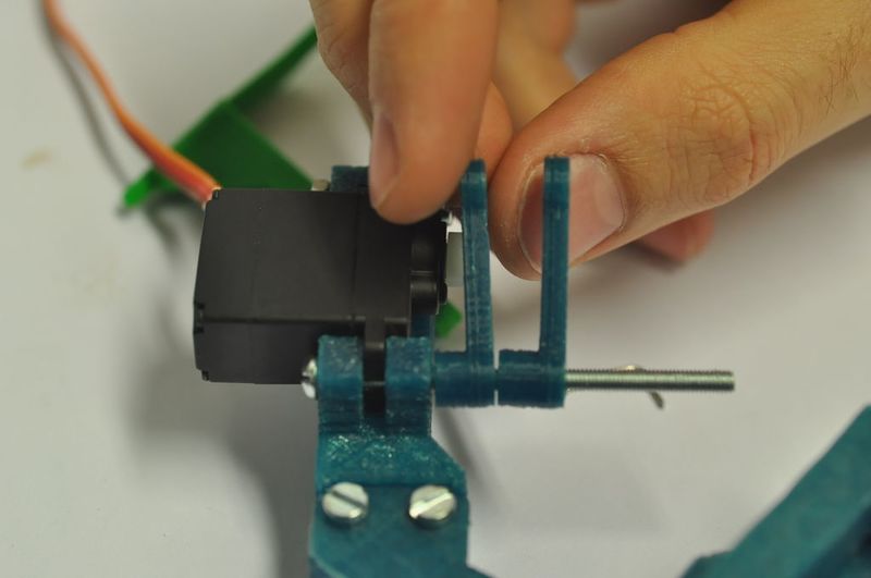
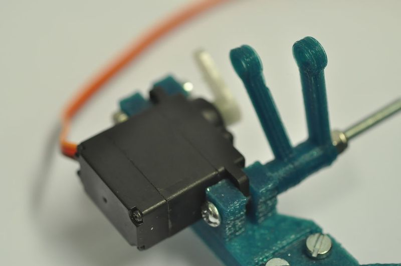
Take the 3D printed 'servo beam mount' part.
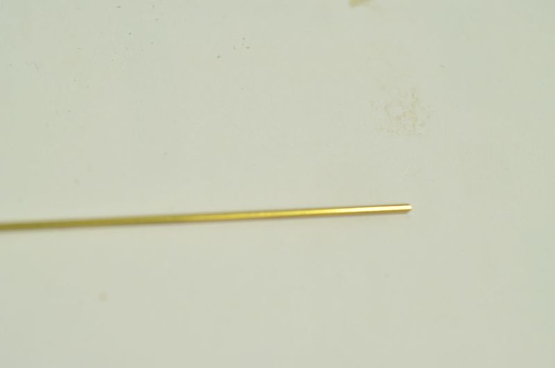
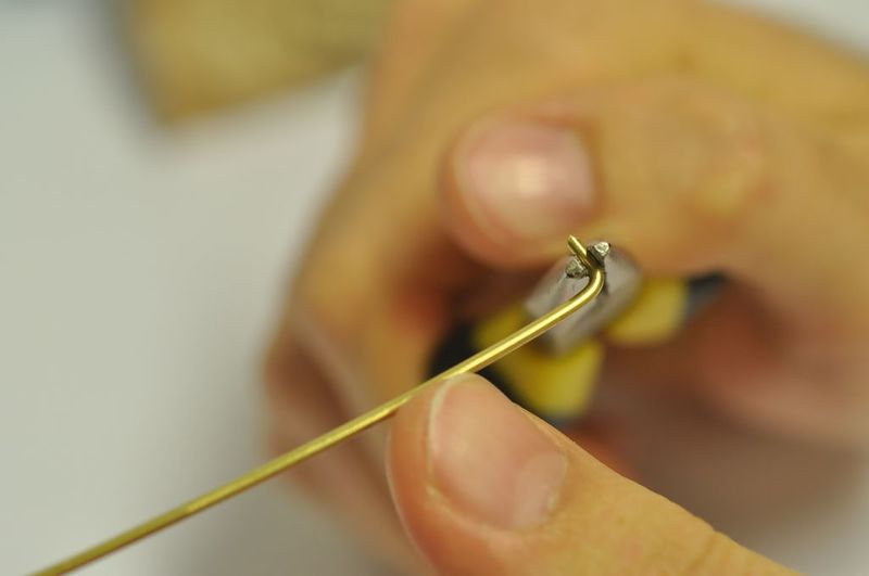
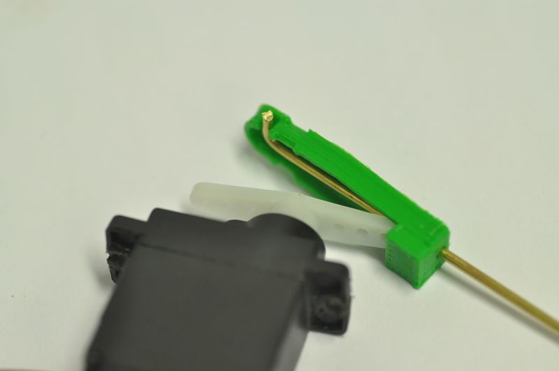
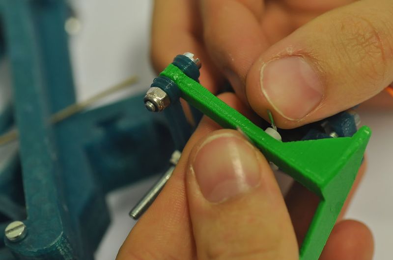
Bend the pin.
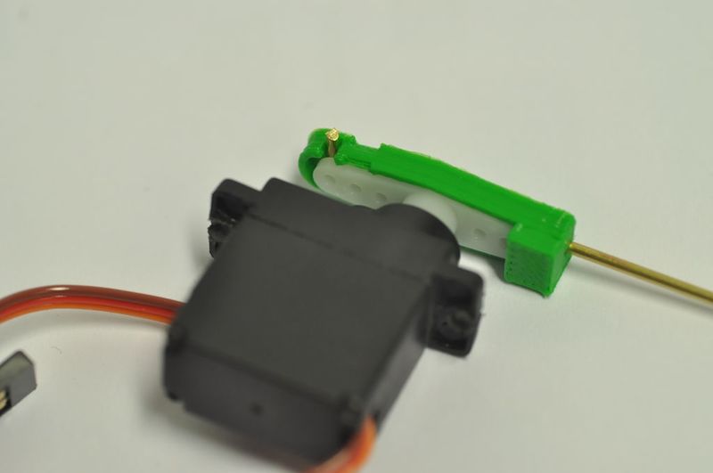
Slide the pin into the part.
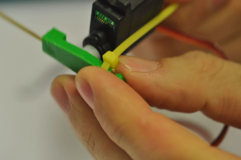
Position it over the servo motor wings.
Tie the pieces together.
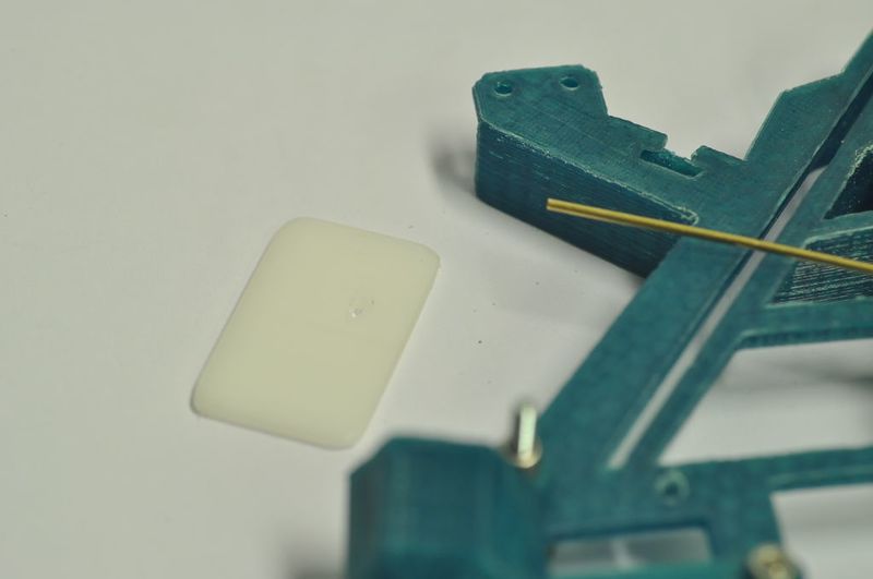
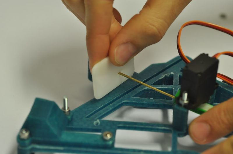
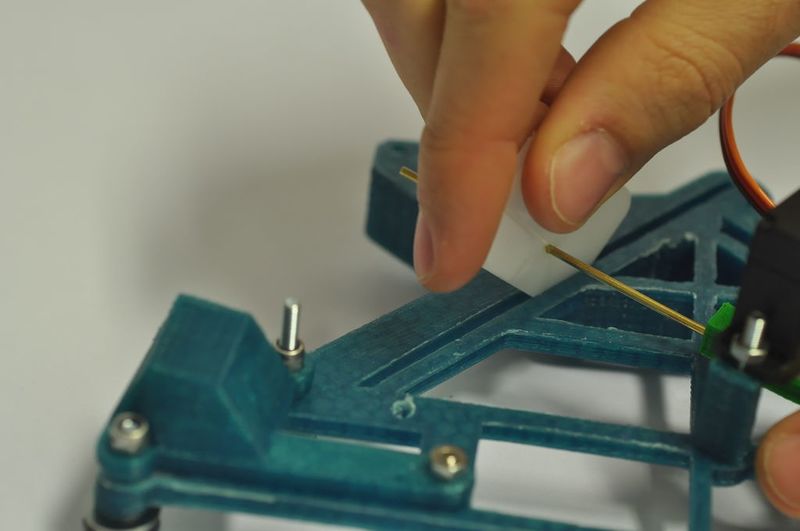
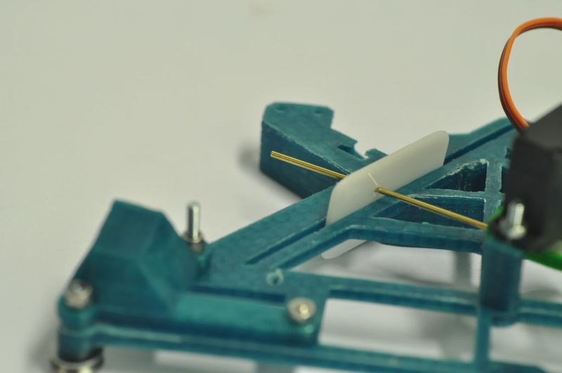
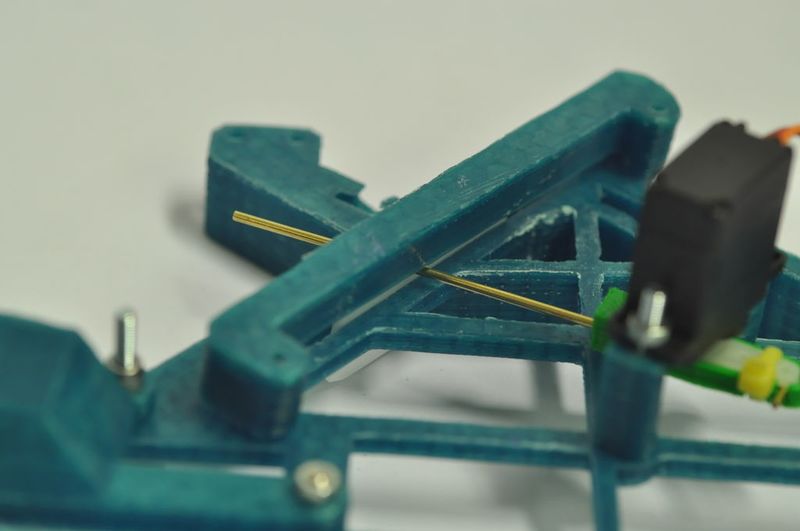
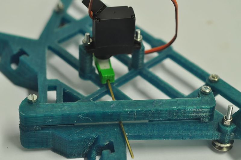
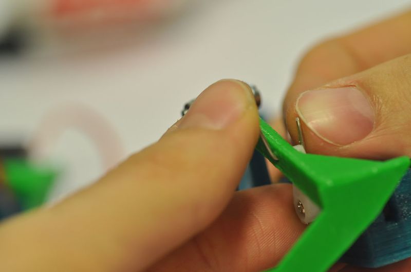
Étape 29 - Assemble the slider part
Take the white acrylic 'slider' square.
Position it on the pin.
Place it in the slid as indicated in the image. Now it should be able to slide.
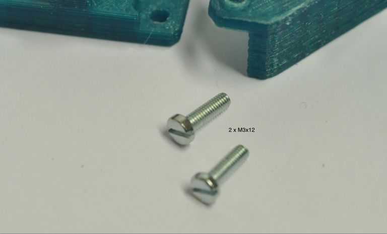
Attach the 3D printed 'slider guide' on top with M3 cross bolts.
Étape 30 - Prepare the SLED mechanism
Use two M3 x 12 bolts.
To place the 'sled mount' on the carriage.
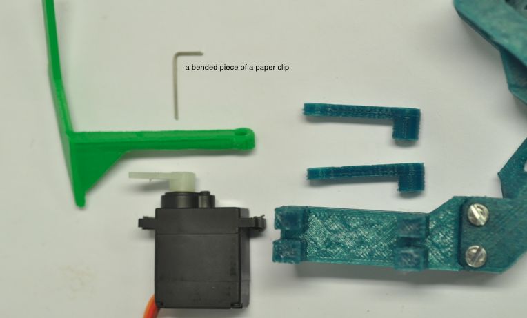
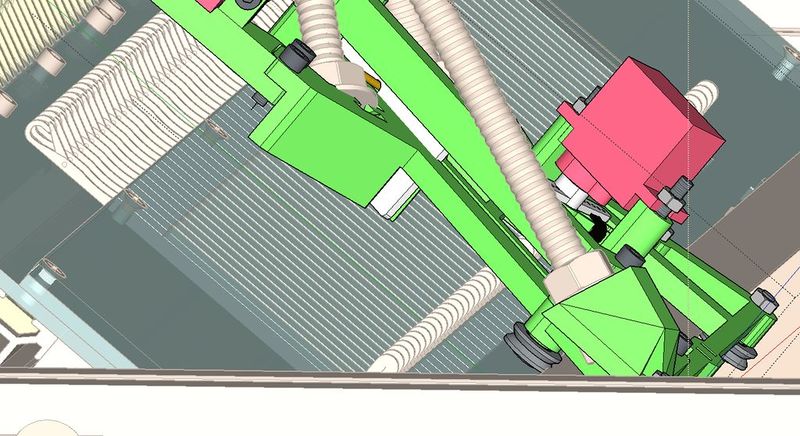
Take 'sled', 'sled arms' and a servo motor, plus a bended paperclip.
Make sure the arm of the servo can move as indicated with the green arrow in the picture.
Étape 31 - Attach the motor
Screw the motor to the sled mechanism using an M3 x 16 bolt.
Slide the long M3x35 bolt through the hole.
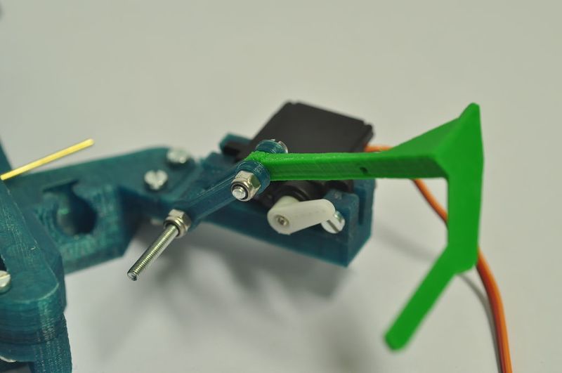
Étape 32 - Add arms
Now slide two of the arms over the 35mm bolt towards the motor. Finish it with a nut with nylon, allowing the arms to turn freely.
Étape 33 - Almost done with the carriage...
At the top side of the arms, attach the bright green part, using a nut with nylon again. The sled should move freely.
Pull the paper clip though the wing of the motor and the bright green part and bend it to fix it, as shown in the picture.
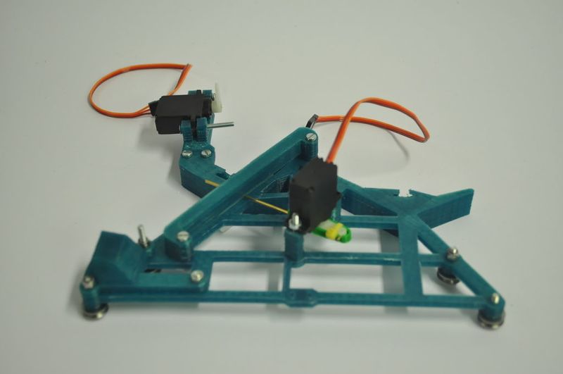
Now you have finished your first carriage piece! There is two of them, so one more to go...
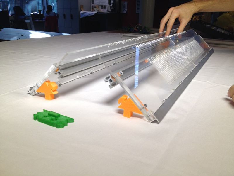
Étape 34 - Make the 'legs' of the machine
Take the four leg parts, place the nut with the help of the bolt.
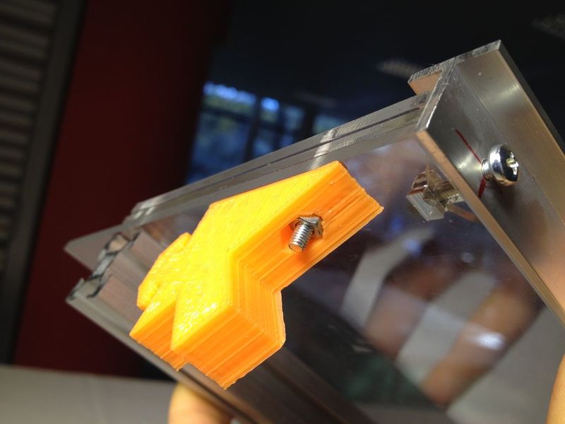
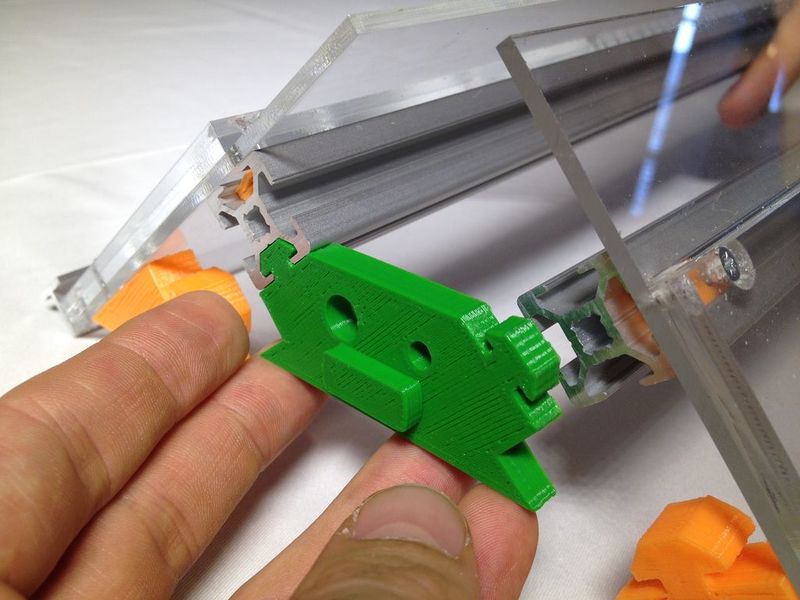
Place them underneath the acrylic assembly.
Slide in the 'space invader'.
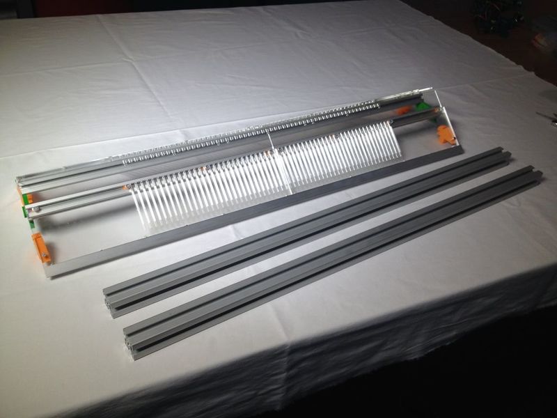
Étape 35 - Place the 3030 profiles
Take the 30 x 30 x 800 mm aluminum bars. Carefully slide the '3030' in, holding the 'leg' parts straight.
Do it really slowly slowly while holding the other 'leg' parts straight.
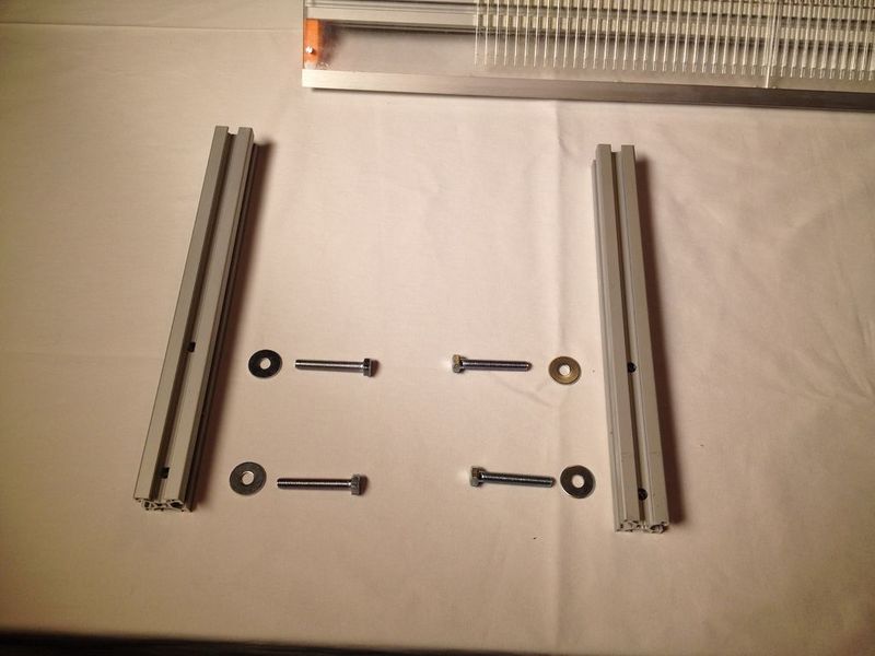
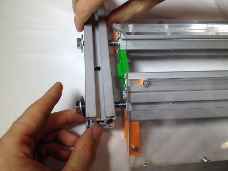
Étape 36 - Place the short aluminum profiles
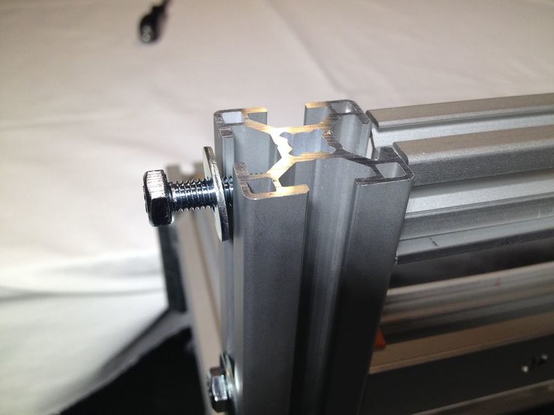
You need the 320 mm long profiles, 4 M8 washers and M8 x 50 bolts.
Place the profiles carefully on the side of the machine, don't tighten them all the way.
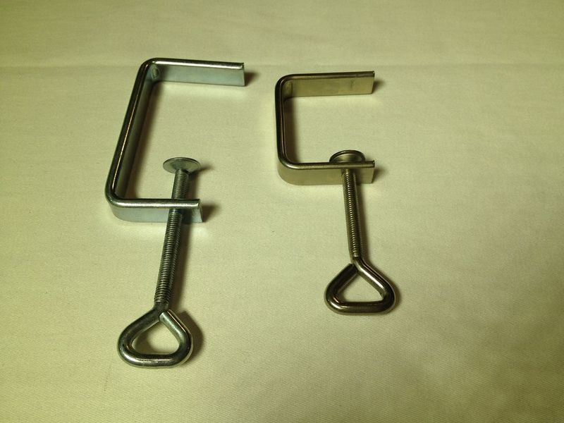
Then get the clamps. It is recommended to have 2 people for this task: clamping the machine on the table.
Étape 37 - Place the vertical short bars
You'll need the 164 mm short aluminum bars, 2 M8 x 50 bolts and M8 washers.
Place the bar as indicated in the picture. Put it so the holes on the side are at the top on the outside.
Étape 38 - Prepare the yarn carrier
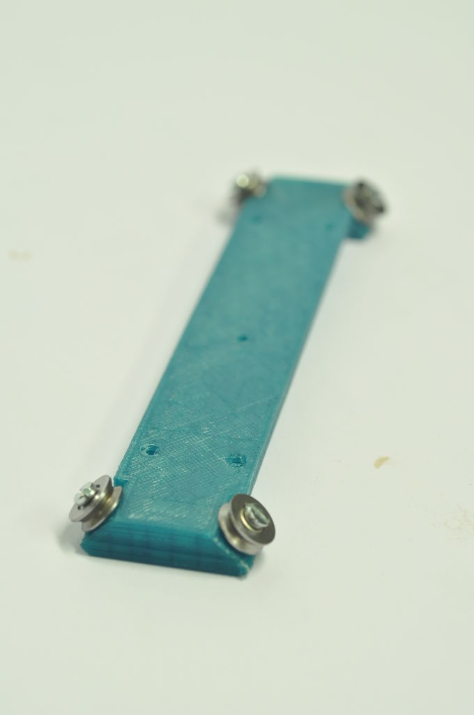
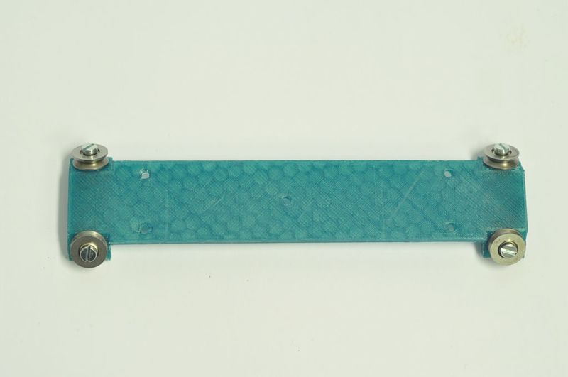
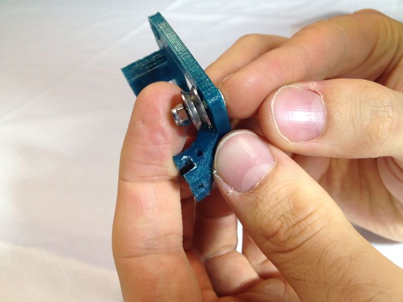
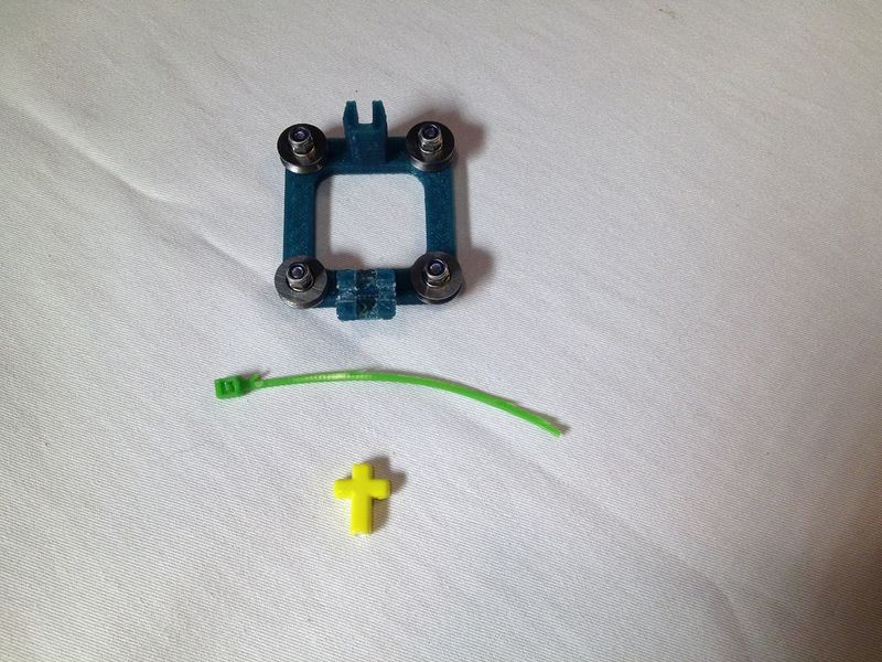
You need the yarn carrier part, 4 M3 nylon nuts, 4 M3x12 countersink bolts and 4 bearings, a cross shaped bead and a tie wrap.
Narrow the tie if yours is too thick.
Tighten the nut without blocking the bearing.
Smooth the cross shaped beads so the thread can move through easily.
Snap the cross in, and use the zip tie carefully.
Étape 39 - Bring the yarn carrier in position
You'll need the 30x30 structural bar 'sandwich', the yarn carrier, two M6 wide washers, and two M6x50 bolts.
Slide the yarn carrier over the length of the bar. Attach the bar horizontally between the vertical short aluminum profiles. Put the bolts all the way in but do not tighten them yet.
Étape 40 - Place the 'L_2020-3030' parts
Take the two parts called L_2020-3030. Slide them carefully down into both the vertical profiles.
Étape 41 - Bring the encoder rack into position
You'll need the 20x20x800 mm bar with the encoder rack inside, two of the 'L_2020-3030' parts, two M6 wide washers and two M6x50 bolts.
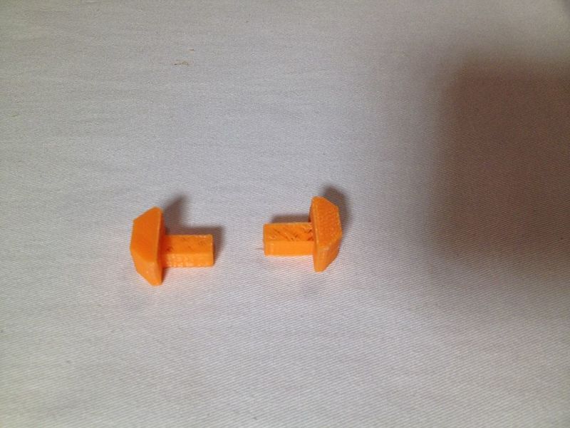
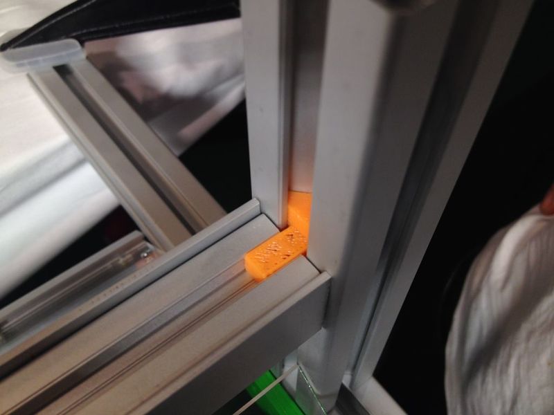
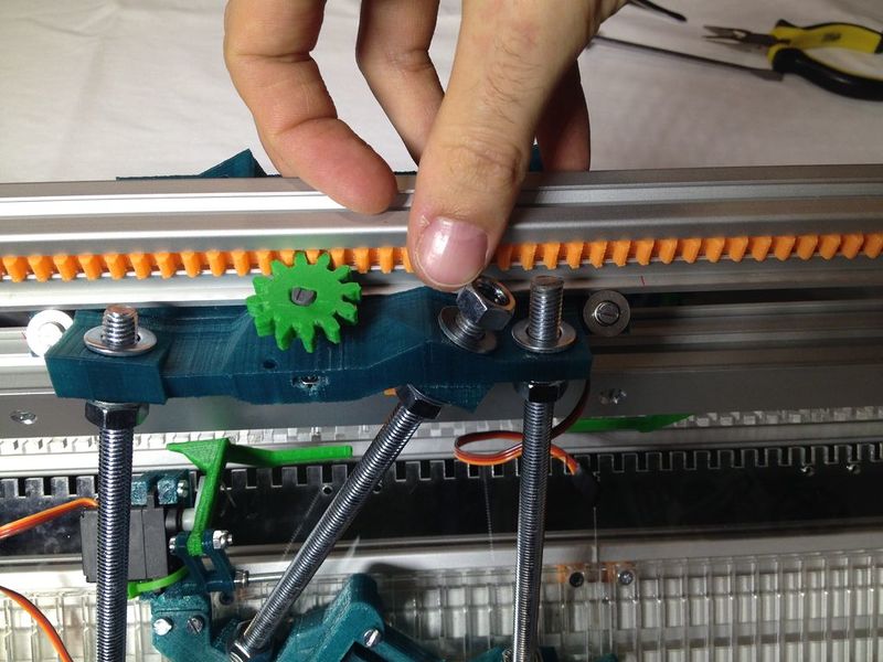
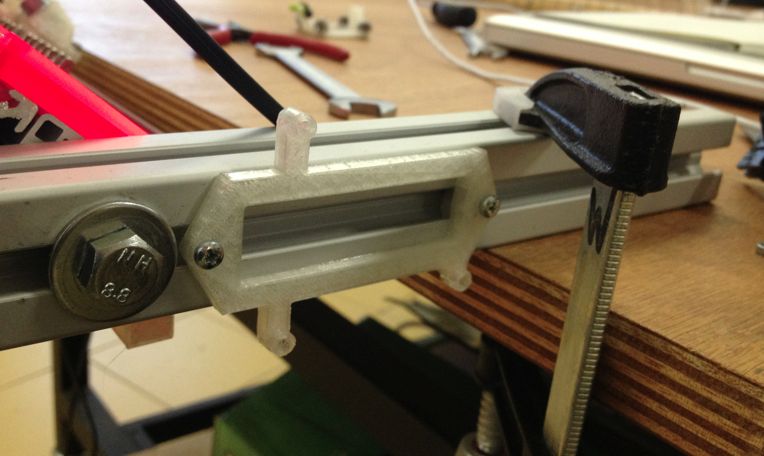
Place the orange part inside between the profile and the rail and slide it into the 3030 profile 164 mm from both sides simultaneously.
Put the bolts through but do not tighten yet.
Étape 42 - Place the carriages
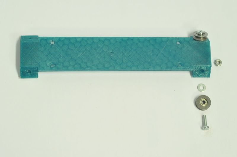
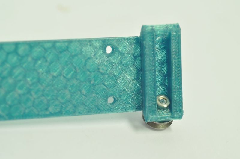
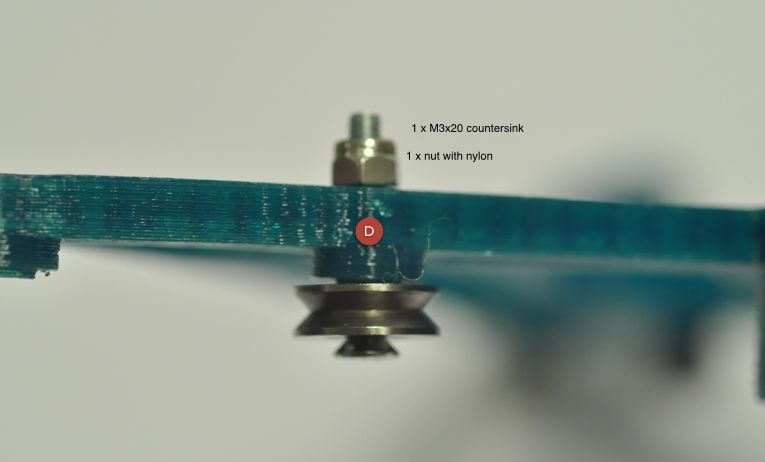
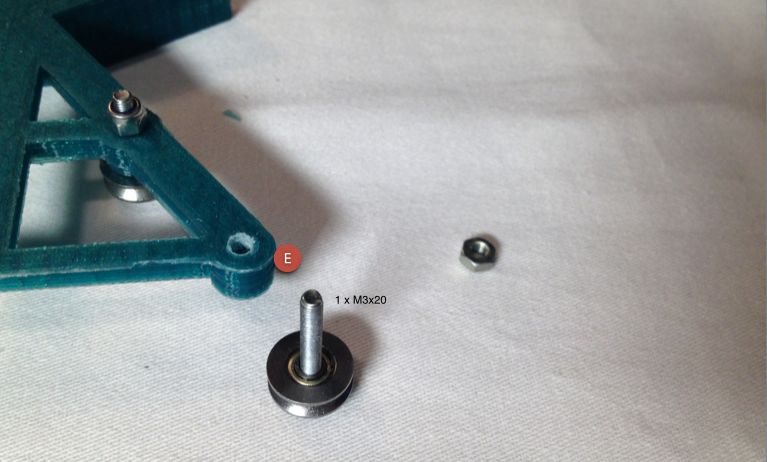
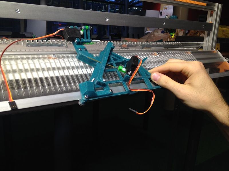
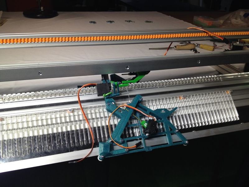
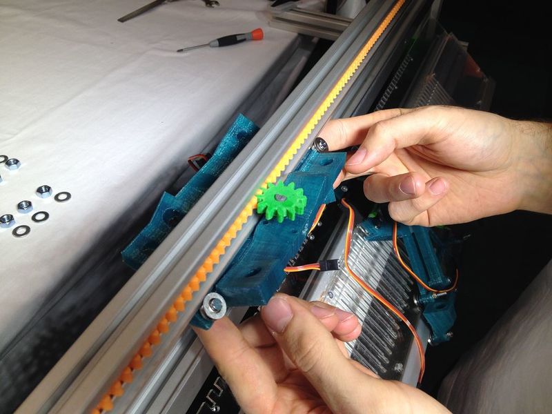
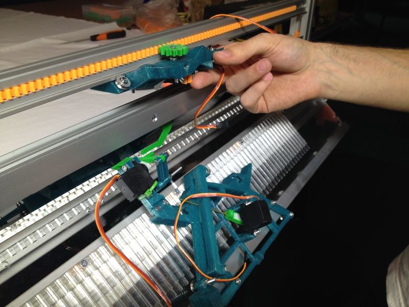
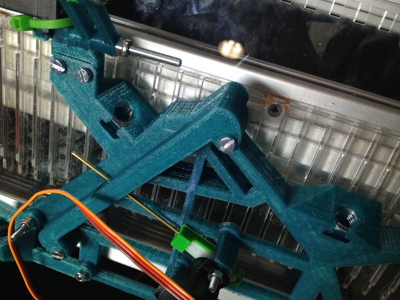
Take the carriage and prepare the bolt with the bearing for later.
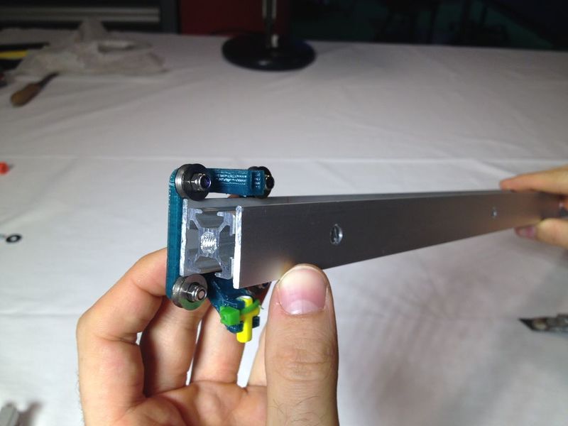
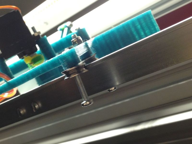
Insert the carriage into the rail carefully and put it in place. Carefully insert the M3x20 bolt as indicated in the third image. The bolt should go all the way in.
Étape 43 - Place the top carriage
You'll need the six threaded rods, 22 x M8 nuts, 18 x M8 washers, and the top carriage.
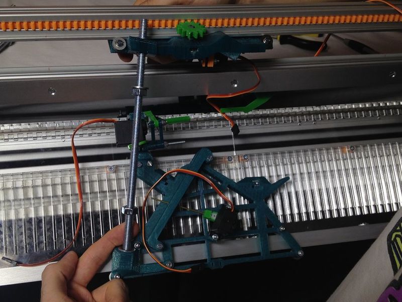
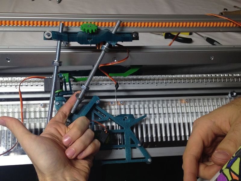
Insert the top carriage assembly, the bearings of the top carriage fit on the bottom of the rail.
Étape 44 - Place nuts for the rods
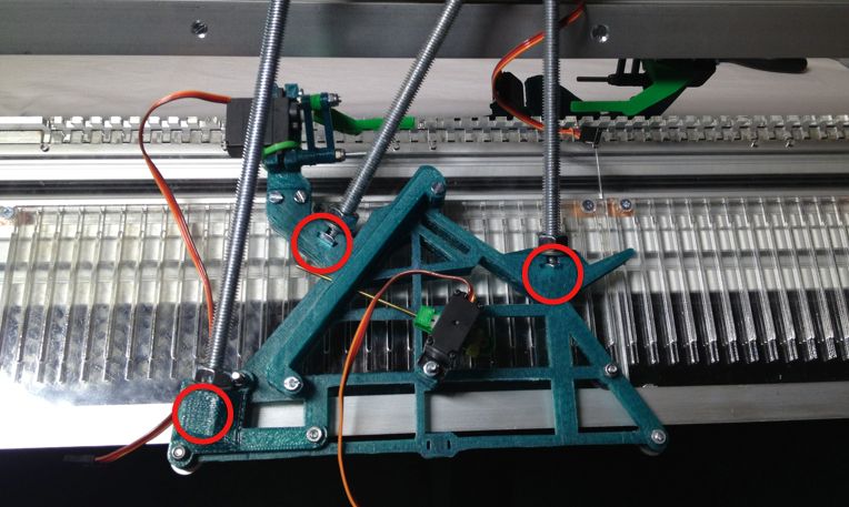
Insert the nuts in the carriage holes, lifting the carriage a little bit. Place one nut in both sides of each carriage.
Étape 45 - Place the rods
Start on the left. Then put the middle one (165mm), and finally the right one (155mm). Tighten the three rods in the bottom trapped nuts.
Étape 46 - Place nuts on top of the rods
Do not tighten them all the way yet.
Étape 47 - Insert the 'teeth'
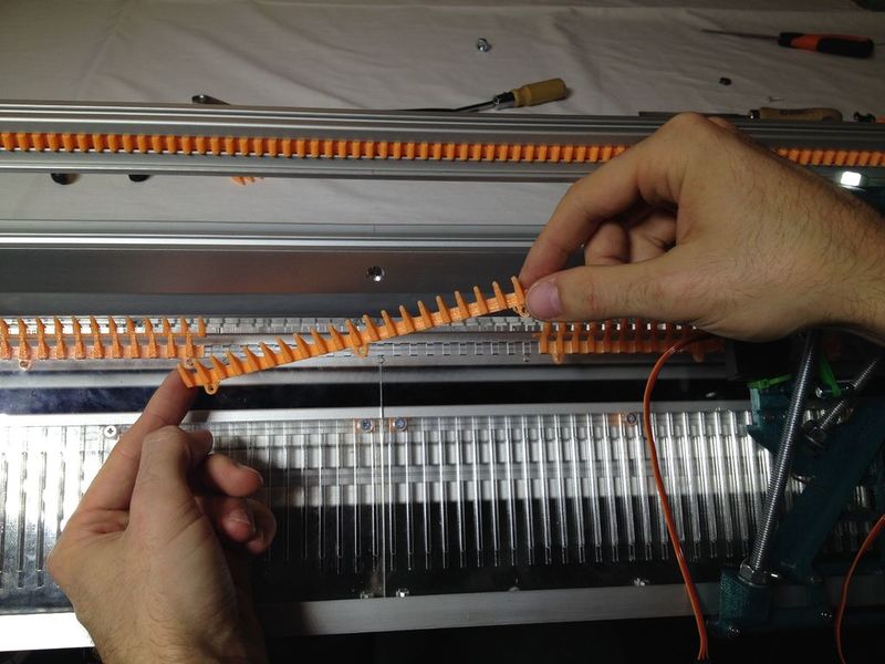
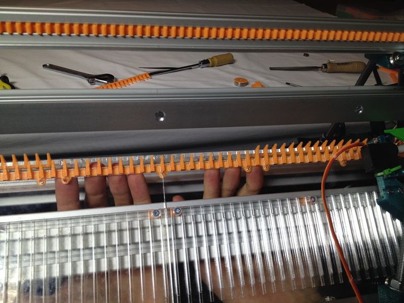
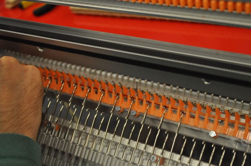
Insert each set of “teeth” from the bottom. You can snap them in place.
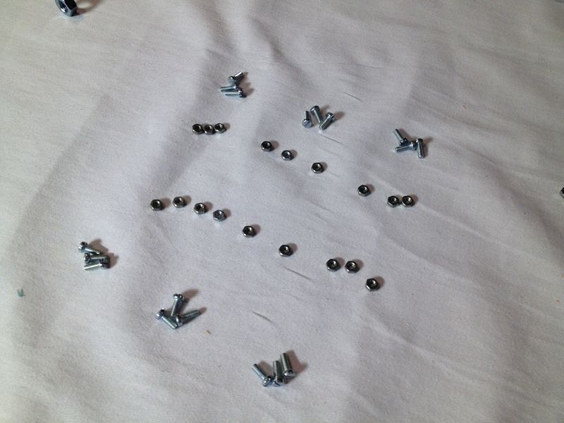
Then you'll need 18 x M3x8 bolts and 18 M3 nuts. First insert all the bolts, then fix them with the nuts.
Étape 48 - Prepare the bearing for the motor
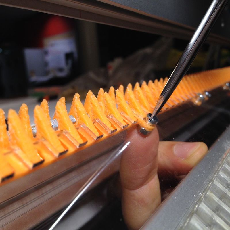
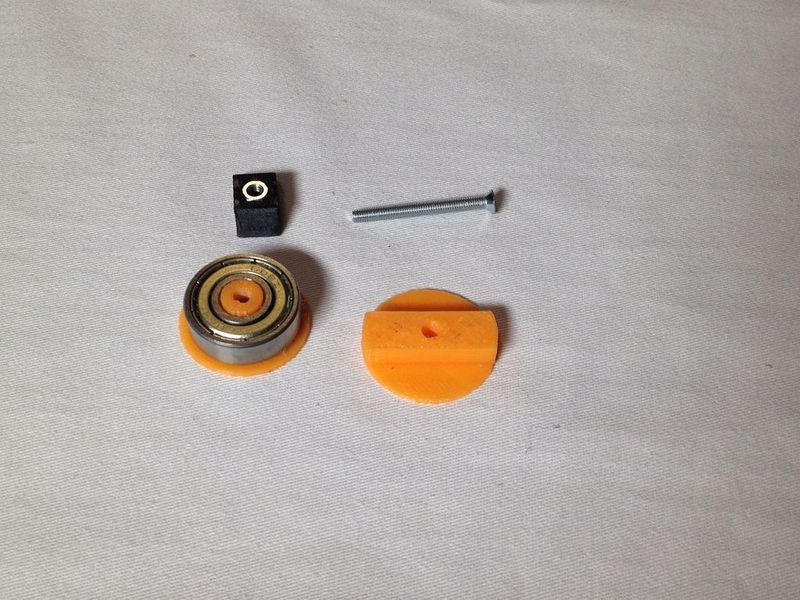
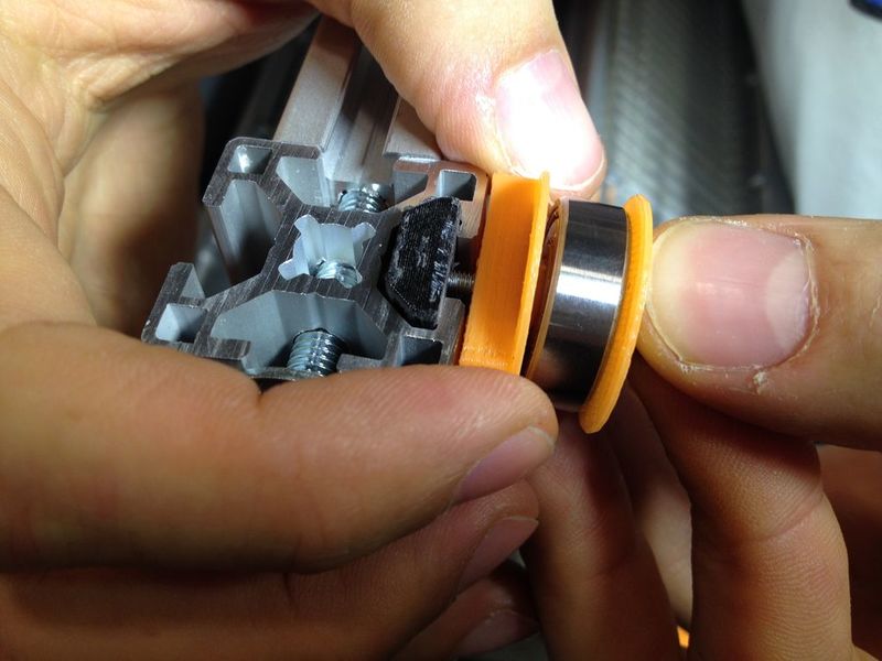
Take “bearing608_mount” and fit a 608 bearing in. Take “3030nut” and place a nut inside. Put all the parts together as indicated in the image, then slide it into the vertical (short) profile).
Étape 49 - Assemble the stepper motor holder
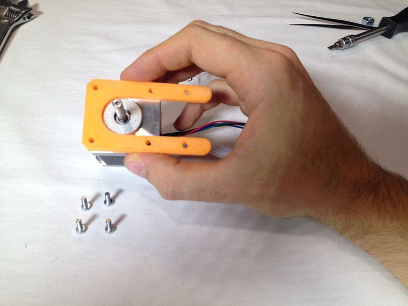
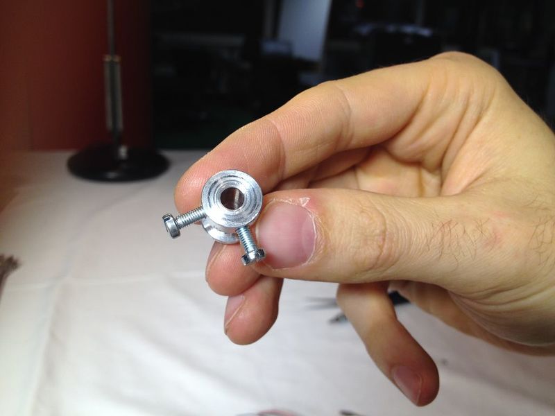
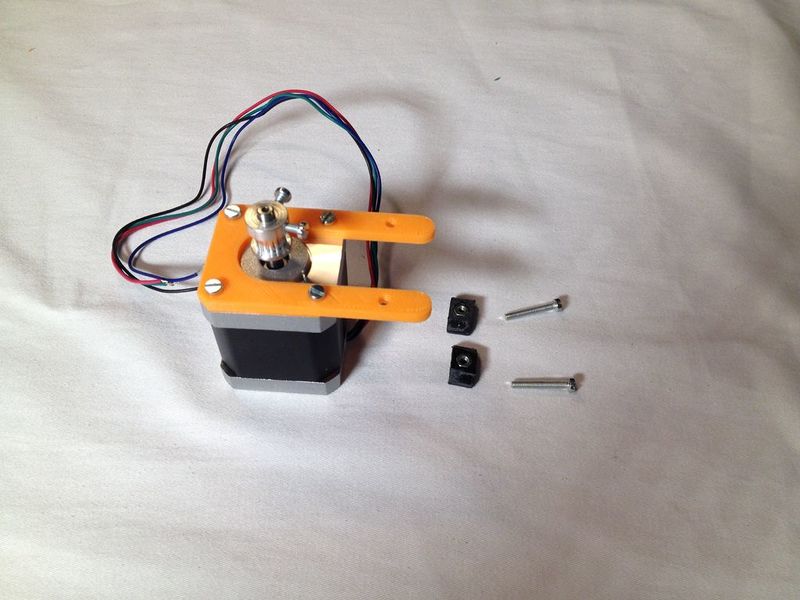
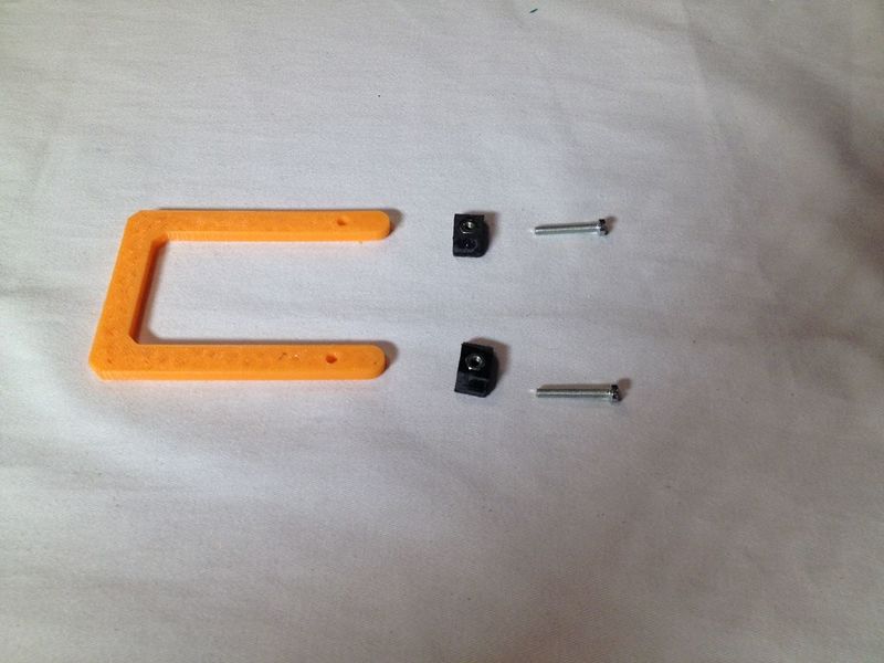
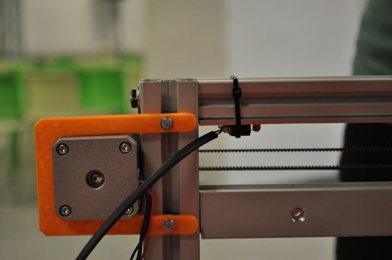
Take “stepper_mount” and the stepper motor. Tight the stepper mount on top of the motor. Take the pulley and 2 M3 x 8 bolts. Insert the bolts as indicated in the third image. Take two “3030nut” and place the nuts in. You'll need this for the next step.
Étape 50 - Place the stepper motor
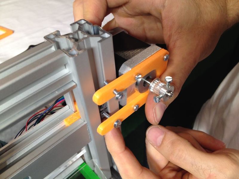
First insert the nuts in the profile and then catch them with the bolt.
Étape 51 - Attach the back side of the motor.
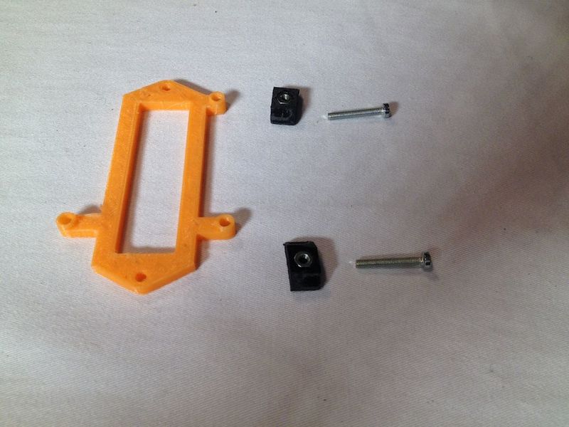
Take “stepper_mount_back” and two “3030nut” parts, with nuts inserted. Repeat the process on the other side.
Étape 52 - Attach the Arduino
Use the part 'Arduino_mount', and two “3030nut” in which you insert nuts.
On the horizontal bar that is attached to the table, attach the Arduino mount. Place the Arduino with a couple of bolts.
Étape 54 - Place the Arduino shield
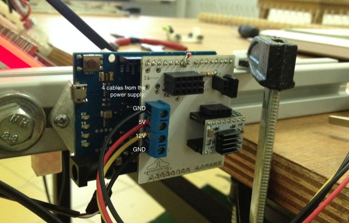
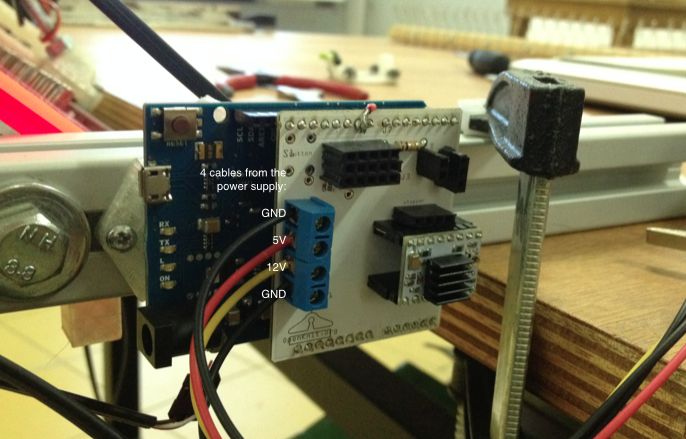
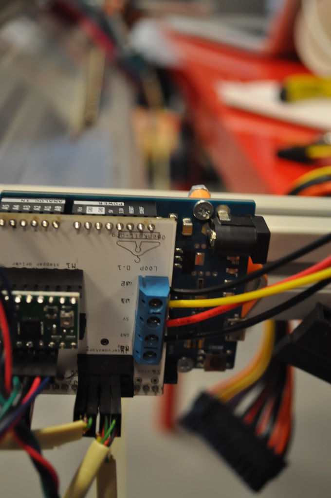
Plug it on top of the Arduino. Connect the 4 cables from the power supply: GND, 5V, 12V, and GND.
Étape 55 - Connect the Arduino shield
Connect the rest of the cables as in the image: 4 servomotors, 1 encoder, 1 endstop and 1 stepper.
Étape 56 - Prepare the tensor - side 1
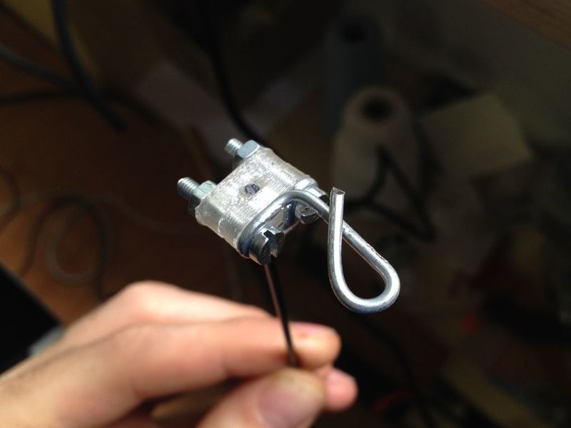
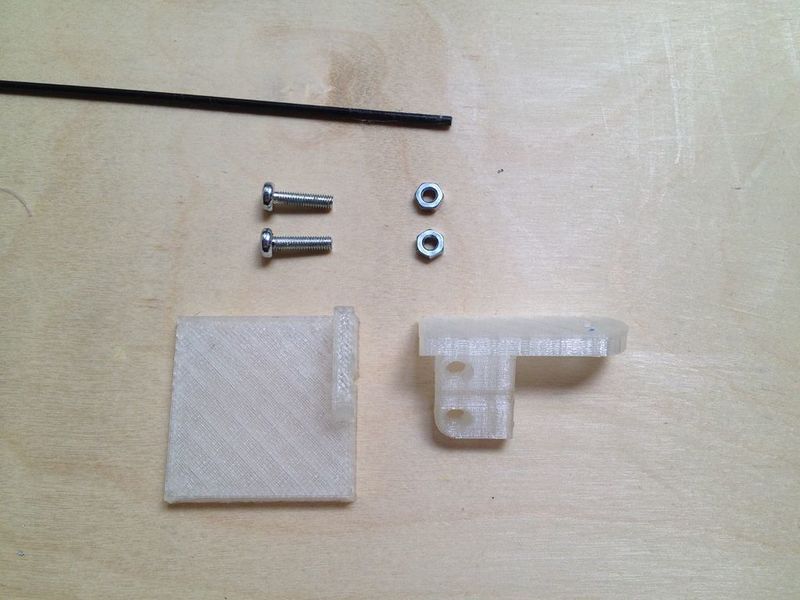
Bend a wire like in the picture and fix it with the two “tensor_head” parts on one side of the tensor. You need two M3x16 bolts and nuts.
Étape 57 - Prepare the tensor - side 2
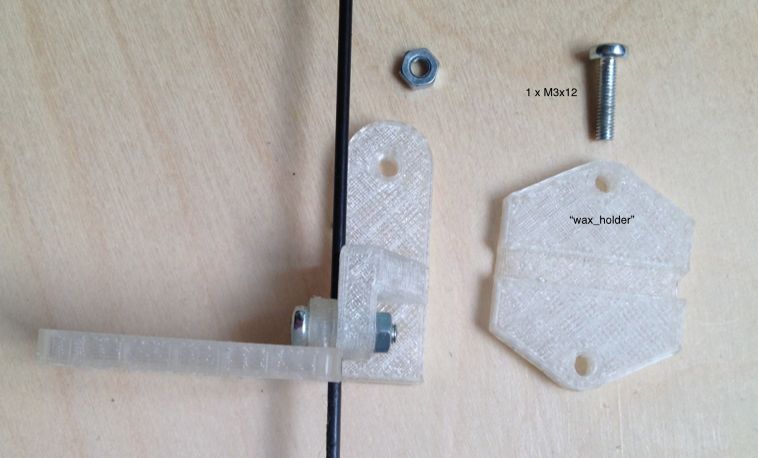
On the other side of the tensor, use 2 x M3x12 bolts and M3 nuts, the 'tensor_table_Top' and the 'tensor_table_wax'. Put them together as shown in the images.
Then add the 'wax_holder' with M3x12 bolts and nuts.
Étape 58 - Prepare the paraffin block
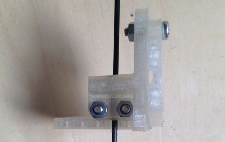
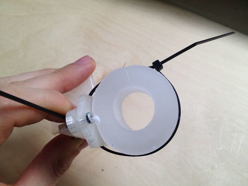
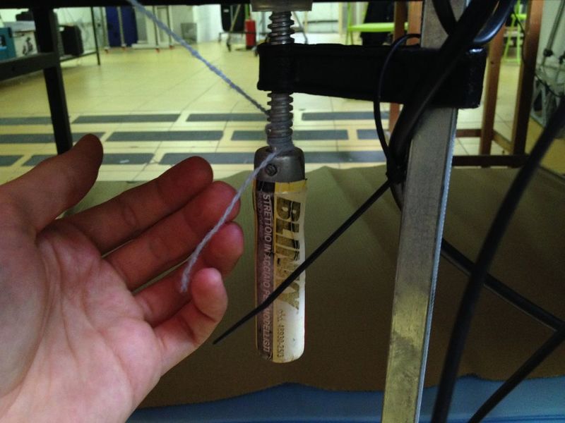
You'll need a block of paraffin (or wax), the assembly you just made and a tie-wrap.
Pull the tie-wrap around the paraffin block.
Take the piece called “tensor_table_bottom” and place it at the end of the tensor.
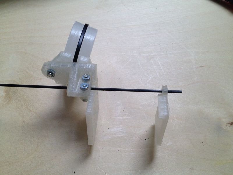
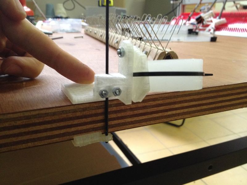
Étape 59 - Clamp the paraffin block
Put the table in between the two flat pieces. Clamp the assembly to the table close to the knitting machine.
Étape 60 - Thread the machine - part 1
Well done, we can finally start threading!
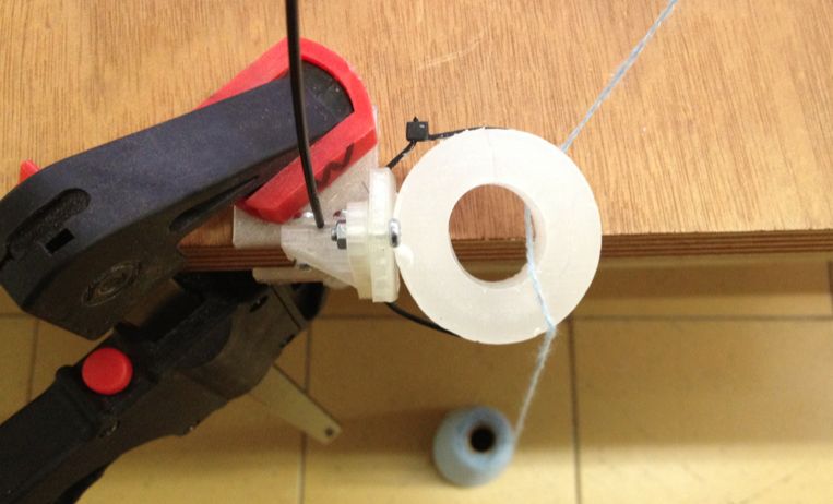
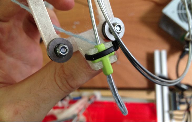
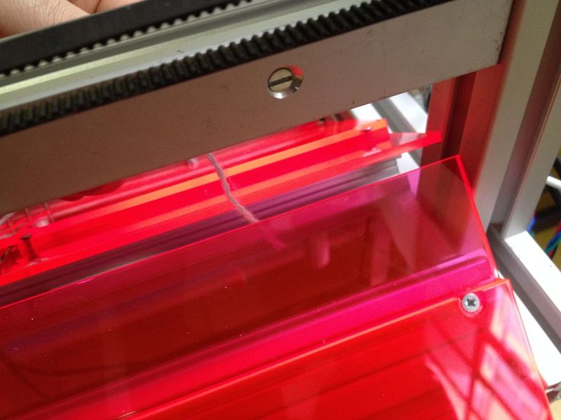
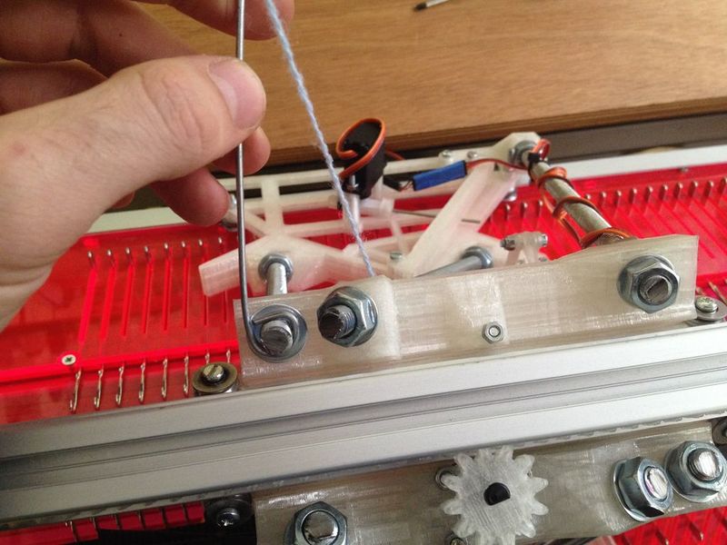
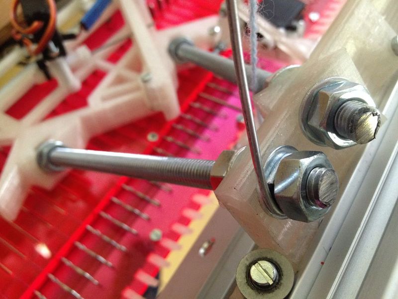
Place the yarn on the floor, the first step is to pull it up through the paraffin donut. Then it goes through the carrier. Use a wire to pull the thread through the cross shaped bead.
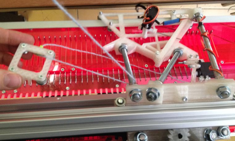
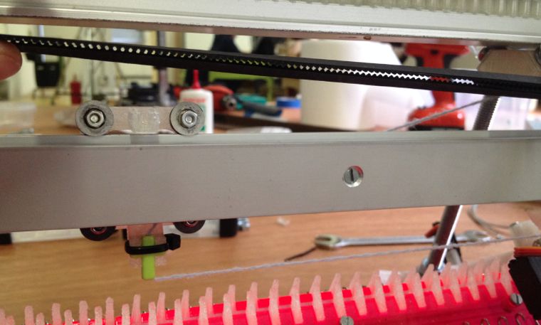
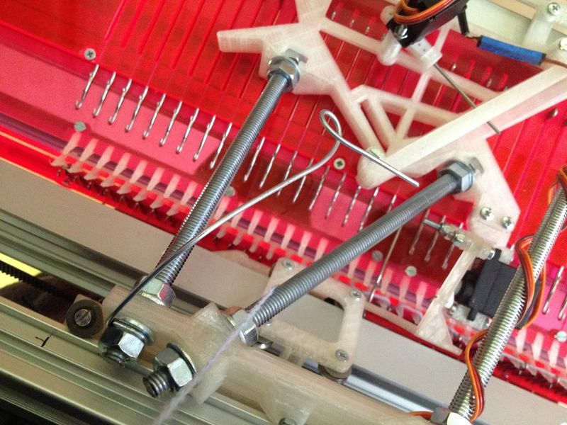
Then, pass the yarn carrier in between the threaded rods. (image 4) and place the yarn carrier in the rail. Unscrew the top 2 bolts if needed (image 5). It should look like image 6.
Pass the thread through the two needle beds. Pull it carefully downwards. Attach it somewhere, for example at the clamps that hold the machine to the table.
Étape 62 - Thread the machine - part 2
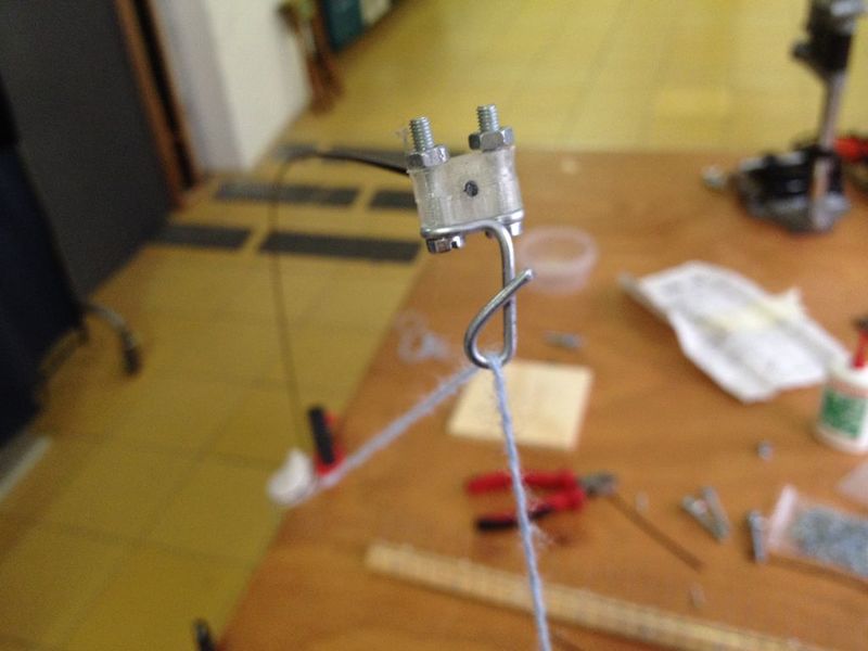
Pull the wire up through the eye of the top part of the tensor.
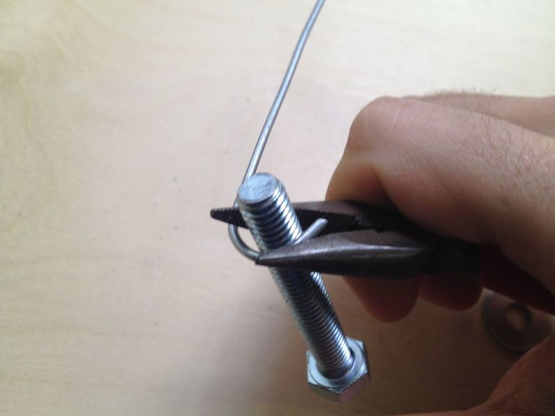
Cut a piece of wire of 200 mm. Bend it to make an 'eye', use an M8 rod to help you get it in the right shape.
Unscrew the nut of the left threaded rod and place the bended wire. Put the nut back in place and tighten it.
Pull the thread of yarn up, and bend the tip of the wire into an 'eye' as shown in the picture.
Pass the thread through the eye. The threading is done, and you have finished the building part of making the Open Knit Machine!!!
Étape 64 - Wiring the motors
The motors have to be connected to the Arduino board. Wire them up as shown in the schedule and the images.
For this and following steps: it is wise to bundle the wires together in tubes.
Étape 65 - Connecting the power supply
The images show how to connect the cables coming from power supply to the Arduino.
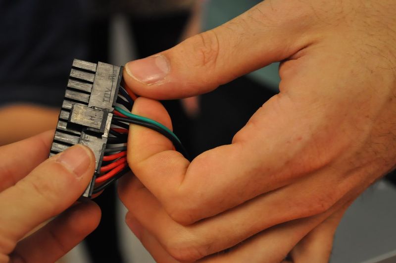
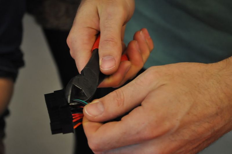
For powering the machine we are using a regular computer power supply, cheap and easy to find. In order to turn it on we have to cut and connect the green and a black cable together from the 20 pin Molex connector.
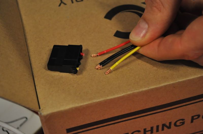
Then grab any 4 pin Molex connector with red, black, black and yellow cables (5V, ground, ground, 12V) and cut them and connect them to the shield like in the image.
[kopie.pdf ]
Étape 66 - Organizing the wires
Make sure the wires will not be in the way when the carriage is moving.
Étape 67 - Calibrating the servo motors
First you need to calibrate the servos.
If you haven’t worked with Arduino yet, install the drivers from the Arduino website. [ http://arduino.cc/en/Guide/ArduinoLeonardoMicro?from=Guide.ArduinoLeonardo ]
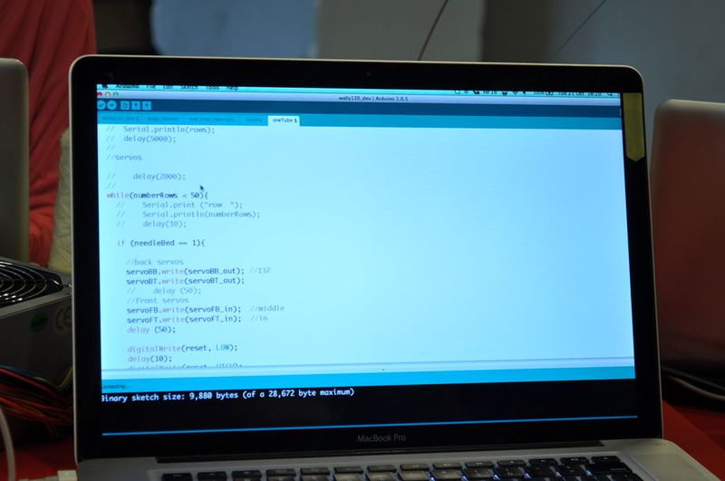
Paste the following code in an Arduino sketch:
//call the Servo library
- include
//In this first block of code you are giving each servo a name.
//It is recommended to refer to their position, like front (F), back(B), //bottom(B) or top (T). The front – top motor is then called servoFT.
Servo servoFB;
Servo servoFT;
Servo servoBB;
Servo servoBT;
//Here we create variables (integers) and assign them a number,
//all the numbers that follows will change for each machine and servo.
//Two variables per servo, that means two positions: in and out.
//”in” means the arm's servo moves into working position and
//”out” means the arm is not in working position.
//the number refers to the angle position of the arm.
int servoFB_in = 119;
int servoFB_out = 92;
int servoFT_in = 54;
int servoFT_out = 160;
int servoBB_in = 67;
int servoBB_out = 100;
int servoBT_in = 88;
int servoBT_out = 150;
void setup()
{
//here we indicate in which pin is connected each servo.
servoFB.attach(7); //this means that servoFB is connected to pin 7
servoFT.attach(8);
servoBB.attach(9);
servoBT.attach(10);
}
void loop()
{
//we use the variables created before so we don't have to be using numbers here
//this way we just work on the above part of the code making it easier.
servoFB.write(servoFB_in);
servoFT.write(servoFT_in);
servoBB.write(servoBB_in);
servoBT.write(servoBT_in);
//we use a delay of 3 seconds to see what the motor does,
//the delay allow us to see what the motor does before it starts moving again
delay (3000);
servoFB.write(servoFB_out);
servoFT.write(servoFT_out);
servoBB.write(servoBB_out);
servoBT.write(servoBT_out);
//a delay of 1 second allows us to know if we are in working position or not
delay (1000);
}
Étape 68 - Running the code for knitting
In the Arduino software, under Tools > Board, select board: Leonardo.
And select the usb port in Tools > Port
First check for errors. Sometimes the Leonardo board gives troubles uploading and gives errors, but anyway it works. Just try to go ahead (in Arduino 1.5.8 this problem is solved).
When you have uploaded the code, it's running but the motors won't move. They will move only when you switch on the power supply.
With the power supply switched on, check if the arms are going up and down to the proper position. Check the images for the right positions. Test and if they are not ok then type another angle and upload again.
Check the images for the position “servoXB_in”, “servoXB_out”, “servoXT_in” and “servoXT_out”
X stands for Front (F) or Back (B), same position in the front and the back needle bed for both bottom and top servos.
Étape 69 - Preparing for knitting
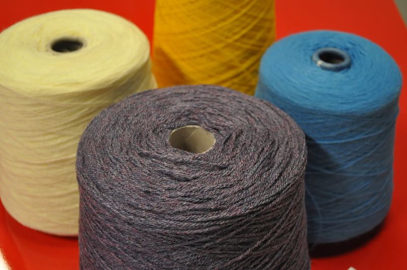
Use a fine wax coated yarn on a cone for machine knitting. Usually the the lighter the colour of the yarn, the smoother it is.
Pass the yarn through every other needle in the front needle bed first. Then do the same in the back needle bed untill you get something like in the picture. Here is where you decide the width of the garment, by picking the desired amount of needles.
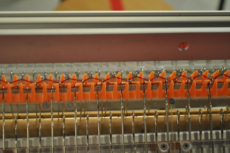
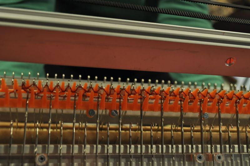
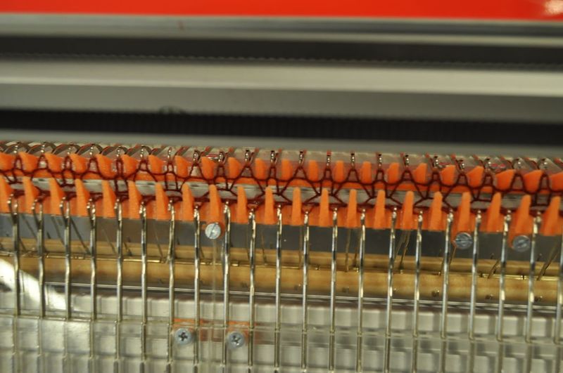
Place the comb like in the picture, make sure that every hook/paper clip is grabing the thread in the spaces between two needles. The hook doesn't have to grab the thread that is not in between needles.
Étape 70 - Knitting
Download the file from GitHub:
https://github.com/g3rard/OpenKnit/tree/master/Wal...
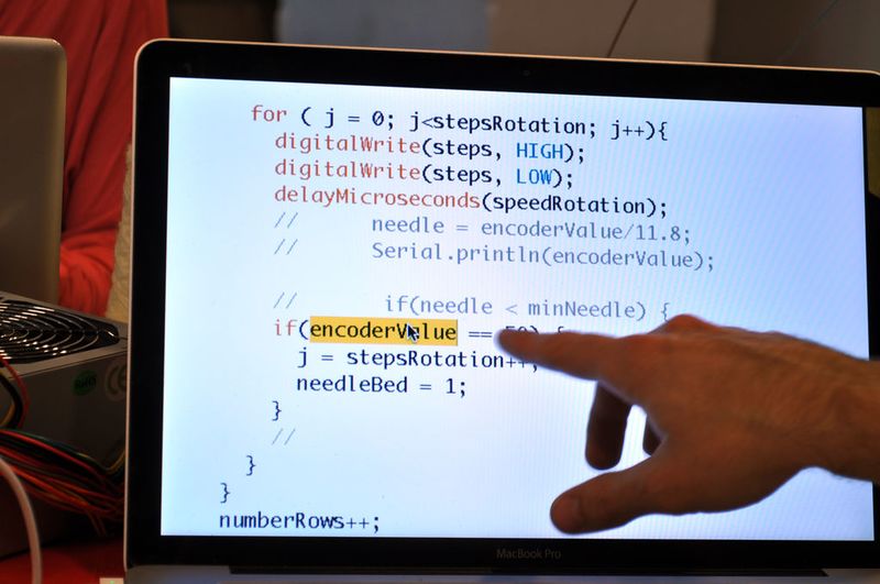
Once we have the comb in place the machine is ready to knit automatically. To let the machine now the width we have to uncomment the following line to print the encoder value on the Serial Monitor:
//Serial.println(encoderValue);
Then we introduce the value in both conditionals in the front bed (needleBed = 1) and the back needle bed (needleBed = 2)
The variable numberRows indicates the length of the garment. A row is equal to the movement of the carriage back and forth from homing position once
The machine is now ready to knit by itself.
In case the carriage gets stuck it could be the wire tension is not good. Tension of the thread is crucial. A lot depends on the material of the tensor. A real piano string works well and can be bought at a piano shop or hardware store, in this case a carbon fiber stick was used.
Published


 Français
 English
 Deutsch
 Español
 Italiano
 Português