(Cette version a été marquée pour être traduite) |
|||
| Ligne 2 : | Ligne 2 : | ||
|Main_Picture=Wooden_pet_connects_to_Facebook_6.PNG | |Main_Picture=Wooden_pet_connects_to_Facebook_6.PNG | ||
|Licences=Attribution (CC BY) | |Licences=Attribution (CC BY) | ||
| − | |Description=<translate>In this tutorial we will create a wooden pet that connects to Facebook. It will post a message of your choice on your own timeline whenever its tail is touched.</translate> | + | |Description=<translate><!--T:1--> In this tutorial we will create a wooden pet that connects to Facebook. It will post a message of your choice on your own timeline whenever its tail is touched.</translate> |
|Area=Electronics | |Area=Electronics | ||
|Type=Creation | |Type=Creation | ||
| Ligne 23 : | Ligne 23 : | ||
{{ {{tntn|Separator}}}} | {{ {{tntn|Separator}}}} | ||
{{ {{tntn|Tuto Step}} | {{ {{tntn|Tuto Step}} | ||
| − | |Step_Title=<translate>Setup an account and create a new feed on adafruit.io</translate> | + | |Step_Title=<translate><!--T:2--> Setup an account and create a new feed on adafruit.io</translate> |
| − | |Step_Content=<translate>Create a new feed by reaching https://io.adafruit.com/ > Feeds > Actions and then name it, for example “touchsensor”</translate> | + | |Step_Content=<translate><!--T:3--> Create a new feed by reaching https://io.adafruit.com/ > Feeds > Actions and then name it, for example “touchsensor”</translate> |
|Step_Picture_00=Wooden_pet_connects_to_Facebook_2.PNG | |Step_Picture_00=Wooden_pet_connects_to_Facebook_2.PNG | ||
|Step_Picture_01=Wooden_pet_connects_to_Facebook_1.PNG | |Step_Picture_01=Wooden_pet_connects_to_Facebook_1.PNG | ||
}} | }} | ||
{{ {{tntn|Tuto Step}} | {{ {{tntn|Tuto Step}} | ||
| − | |Step_Title=<translate>Install Arduino IDE</translate> | + | |Step_Title=<translate><!--T:4--> Install Arduino IDE</translate> |
| − | |Step_Content=<translate>You will need to use Arduino IDE to code and upload the firmware onto your ESP32 board. | + | |Step_Content=<translate><!--T:5--> |
| + | You will need to use Arduino IDE to code and upload the firmware onto your ESP32 board. | ||
| + | <!--T:6--> | ||
Download the software by visiting [https://www.arduino.cc/en/Main/Software? Arduino IDE] > Scroll down until you see the “Download the Arduino IDE” section and choose the version based upon your operating system (e.g. If you have Windows 7, choose “Windows Installer” / if you have Windows 10, choose “Windows app”) > On the next page choose “Just download” and run the installation files.</translate> | Download the software by visiting [https://www.arduino.cc/en/Main/Software? Arduino IDE] > Scroll down until you see the “Download the Arduino IDE” section and choose the version based upon your operating system (e.g. If you have Windows 7, choose “Windows Installer” / if you have Windows 10, choose “Windows app”) > On the next page choose “Just download” and run the installation files.</translate> | ||
}} | }} | ||
{{ {{tntn|Tuto Step}} | {{ {{tntn|Tuto Step}} | ||
| − | |Step_Title=<translate>Prepare the ESP32 board on your computer</translate> | + | |Step_Title=<translate><!--T:7--> Prepare the ESP32 board on your computer</translate> |
| − | |Step_Content=<translate>Follow the [https://github.com/espressif/arduino-esp32/blob/master/README.md#installation-instructions instructions provided on GitHub] for your Operating System. For example, if you have Windows 7 or 10, choose “Instructions for Windows” / if you have a MacBook, choose “Instructions for Mac” | + | |Step_Content=<translate><!--T:8--> |
| + | Follow the [https://github.com/espressif/arduino-esp32/blob/master/README.md#installation-instructions instructions provided on GitHub] for your Operating System. For example, if you have Windows 7 or 10, choose “Instructions for Windows” / if you have a MacBook, choose “Instructions for Mac” | ||
| + | <!--T:9--> | ||
For the “Instructions for Windows” section, you can ignore the following step:</translate> | For the “Instructions for Windows” section, you can ignore the following step:</translate> | ||
|Step_Picture_00=Wooden_pet_connects_to_Facebook_Capture.PNG | |Step_Picture_00=Wooden_pet_connects_to_Facebook_Capture.PNG | ||
}} | }} | ||
{{ {{tntn|Tuto Step}} | {{ {{tntn|Tuto Step}} | ||
| − | |Step_Title=<translate>Check that the board is correctly configured</translate> | + | |Step_Title=<translate><!--T:10--> Check that the board is correctly configured</translate> |
| − | |Step_Content=<translate>Launch Arduino IDE and select “ESP32 Dev Module” from the Tools menu > Board. | + | |Step_Content=<translate><!--T:11--> |
| + | Launch Arduino IDE and select “ESP32 Dev Module” from the Tools menu > Board. | ||
| + | <!--T:12--> | ||
Fetch the Blink example from File > Examples > 01.Basics > Blink. | Fetch the Blink example from File > Examples > 01.Basics > Blink. | ||
| + | <!--T:13--> | ||
write int LED_BUILTIN = 2; at the top of the code | write int LED_BUILTIN = 2; at the top of the code | ||
| + | <!--T:14--> | ||
/* | /* | ||
| + | <!--T:15--> | ||
ESP 32 Blink | ESP 32 Blink | ||
| + | <!--T:16--> | ||
Turns on an LED on for one second, then off for one second, repeatedly. | Turns on an LED on for one second, then off for one second, repeatedly. | ||
| + | <!--T:17--> | ||
The ESP32 has an internal blue LED at D2 (GPIO 02) | The ESP32 has an internal blue LED at D2 (GPIO 02) | ||
| + | <!--T:18--> | ||
<nowiki>*</nowiki>/ | <nowiki>*</nowiki>/ | ||
| + | <!--T:19--> | ||
int LED_BUILTIN = 2; | int LED_BUILTIN = 2; | ||
| + | <!--T:20--> | ||
void setup() | void setup() | ||
| + | <!--T:21--> | ||
{ | { | ||
| + | <!--T:22--> | ||
pinMode(LED_BUILTIN, OUTPUT); | pinMode(LED_BUILTIN, OUTPUT); | ||
| + | <!--T:23--> | ||
} | } | ||
| + | <!--T:24--> | ||
void loop() | void loop() | ||
| + | <!--T:25--> | ||
{ | { | ||
| + | <!--T:26--> | ||
digitalWrite(LED_BUILTIN, HIGH); // turn the LED on (HIGH is the voltage level) | digitalWrite(LED_BUILTIN, HIGH); // turn the LED on (HIGH is the voltage level) | ||
| + | <!--T:27--> | ||
delay(1000); // wait for a second | delay(1000); // wait for a second | ||
| + | <!--T:28--> | ||
digitalWrite(LED_BUILTIN, LOW); // turn the LED off by making the voltage LOW | digitalWrite(LED_BUILTIN, LOW); // turn the LED off by making the voltage LOW | ||
| + | <!--T:29--> | ||
delay(1000); // wait for a second | delay(1000); // wait for a second | ||
| + | <!--T:30--> | ||
} | } | ||
| + | <!--T:31--> | ||
Finally, upload the code by using the right arrow (→) button at the top right corner of the window, by choosing Sketch > Upload or by pressing Ctrl+U on the keyboard.</translate> | Finally, upload the code by using the right arrow (→) button at the top right corner of the window, by choosing Sketch > Upload or by pressing Ctrl+U on the keyboard.</translate> | ||
|Step_Picture_00=Wooden_pet_connects_to_Facebook_4.PNG | |Step_Picture_00=Wooden_pet_connects_to_Facebook_4.PNG | ||
| Ligne 88 : | Ligne 113 : | ||
}} | }} | ||
{{ {{tntn|Tuto Step}} | {{ {{tntn|Tuto Step}} | ||
| − | |Step_Title=<translate>Wiring the LED and the touch sensor to the ESP32</translate> | + | |Step_Title=<translate><!--T:32--> Wiring the LED and the touch sensor to the ESP32</translate> |
| − | |Step_Content=<translate>We will connect an LED to the board so that we will know when the tail actually gets touched. | + | |Step_Content=<translate><!--T:33--> |
| + | We will connect an LED to the board so that we will know when the tail actually gets touched. | ||
| + | <!--T:34--> | ||
Connect a male/female jumper wire to D4 on the board. D4 is by default connected to the internal touch sensor. | Connect a male/female jumper wire to D4 on the board. D4 is by default connected to the internal touch sensor. | ||
| + | <!--T:35--> | ||
Connect D2 (by default connected to the board’s internal LED) to the positive leg of the external LED, using a male to female jumper wire. | Connect D2 (by default connected to the board’s internal LED) to the positive leg of the external LED, using a male to female jumper wire. | ||
| + | <!--T:36--> | ||
Connect the negative leg of the LED to GND on the board, using a male/female jumper wire. | Connect the negative leg of the LED to GND on the board, using a male/female jumper wire. | ||
| + | <!--T:37--> | ||
If needed, use some tape to secure the jumper wires to the LED.</translate> | If needed, use some tape to secure the jumper wires to the LED.</translate> | ||
|Step_Picture_00=Wooden_pet_connects_to_Facebook_6.PNG | |Step_Picture_00=Wooden_pet_connects_to_Facebook_6.PNG | ||
}} | }} | ||
{{ {{tntn|Tuto Step}} | {{ {{tntn|Tuto Step}} | ||
| − | |Step_Title=<translate>Place the electronic board inside the pet</translate> | + | |Step_Title=<translate><!--T:38--> Place the electronic board inside the pet</translate> |
| − | |Step_Content=<translate>The wooden pet needs to be laser cut. You can download the cutting pattern for laser cutter from [https://drive.google.com/file/d/1AHXk4zxDN0U7YNiMKVyBzvakh8pY8MH9/view?usp=sharing here]. | + | |Step_Content=<translate><!--T:39--> |
| + | The wooden pet needs to be laser cut. You can download the cutting pattern for laser cutter from [https://drive.google.com/file/d/1AHXk4zxDN0U7YNiMKVyBzvakh8pY8MH9/view?usp=sharing here]. | ||
| + | <!--T:40--> | ||
Place all the parts inside the pet, and connect the internal touch sensor to the aluminum tail.</translate> | Place all the parts inside the pet, and connect the internal touch sensor to the aluminum tail.</translate> | ||
|Step_Picture_00=Wooden_pet_connects_to_Facebook_7.PNG | |Step_Picture_00=Wooden_pet_connects_to_Facebook_7.PNG | ||
| Ligne 109 : | Ligne 141 : | ||
}} | }} | ||
{{ {{tntn|Tuto Step}} | {{ {{tntn|Tuto Step}} | ||
| − | |Step_Title=<translate>Programming on tuniot</translate> | + | |Step_Title=<translate><!--T:41--> Programming on tuniot</translate> |
| − | |Step_Content=<translate>Let’s create a program that registers the values recorded by the touch sensor and publishes them online. | + | |Step_Content=<translate><!--T:42--> |
| + | Let’s create a program that registers the values recorded by the touch sensor and publishes them online. | ||
| + | <!--T:43--> | ||
For that we need to reach: http://easycoding.tn/esp32/demos/code/ | For that we need to reach: http://easycoding.tn/esp32/demos/code/ | ||
| + | <!--T:44--> | ||
Choose the appropriate blocks to create the code displayed below. | Choose the appropriate blocks to create the code displayed below. | ||
| + | <!--T:45--> | ||
Complete the fields “ssid” and “password” with the name of your wifiwi-fi connection and its password respectively. | Complete the fields “ssid” and “password” with the name of your wifiwi-fi connection and its password respectively. | ||
| + | <!--T:46--> | ||
The “User Name” and “Key” are available here (just click on View AIO Key).</translate> | The “User Name” and “Key” are available here (just click on View AIO Key).</translate> | ||
|Step_Picture_00=Wooden_pet_connects_to_Facebook_9.PNG | |Step_Picture_00=Wooden_pet_connects_to_Facebook_9.PNG | ||
| Ligne 123 : | Ligne 160 : | ||
}} | }} | ||
{{ {{tntn|Tuto Step}} | {{ {{tntn|Tuto Step}} | ||
| − | |Step_Title=<translate>Install Adafruit_MQTT.h and Adafruit_MQTT_Client.h libraries on Arduino IDE</translate> | + | |Step_Title=<translate><!--T:47--> Install Adafruit_MQTT.h and Adafruit_MQTT_Client.h libraries on Arduino IDE</translate> |
| − | |Step_Content=<translate>For that we need to run Arduino IDE and go to Sketch > Include Library > Manage Libraries… > Search for “Adafruit mqtt library” and install the first result.</translate> | + | |Step_Content=<translate><!--T:48--> For that we need to run Arduino IDE and go to Sketch > Include Library > Manage Libraries… > Search for “Adafruit mqtt library” and install the first result.</translate> |
|Step_Picture_00=Wooden_pet_connects_to_Facebook_11.PNG | |Step_Picture_00=Wooden_pet_connects_to_Facebook_11.PNG | ||
}} | }} | ||
{{ {{tntn|Tuto Step}} | {{ {{tntn|Tuto Step}} | ||
| − | |Step_Title=<translate>Programming on Arduino IDE</translate> | + | |Step_Title=<translate><!--T:49--> Programming on Arduino IDE</translate> |
| − | |Step_Content=<translate>To upload the code on Arduino IDE, click on the “Copy Arduino code into clipboard” button. | + | |Step_Content=<translate><!--T:50--> |
| + | To upload the code on Arduino IDE, click on the “Copy Arduino code into clipboard” button. | ||
| + | <!--T:51--> | ||
then paste the code onto Arduino IDE, and upload it to the ESP32. | then paste the code onto Arduino IDE, and upload it to the ESP32. | ||
| + | <!--T:52--> | ||
If you click on Serial Monitor (top right of the Arduino IDE screen, below the “X” button), you should see the values recorded by the touch sensor. | If you click on Serial Monitor (top right of the Arduino IDE screen, below the “X” button), you should see the values recorded by the touch sensor. | ||
| + | <!--T:53--> | ||
It means that your ESP32 is connected to the internet, and that it’s sending the value recorded by the internal touch sensor on-line, on https://adafruit.io.</translate> | It means that your ESP32 is connected to the internet, and that it’s sending the value recorded by the internal touch sensor on-line, on https://adafruit.io.</translate> | ||
|Step_Picture_00=Wooden_pet_connects_to_Facebook_12.PNG | |Step_Picture_00=Wooden_pet_connects_to_Facebook_12.PNG | ||
| Ligne 140 : | Ligne 181 : | ||
}} | }} | ||
{{ {{tntn|Tuto Step}} | {{ {{tntn|Tuto Step}} | ||
| − | |Step_Title=<translate>Create an applet on IFTTT</translate> | + | |Step_Title=<translate><!--T:54--> Create an applet on IFTTT</translate> |
| − | |Step_Content=<translate>For this we need to access https://ifttt.com/ and create an account. | + | |Step_Content=<translate><!--T:55--> |
| + | For this we need to access https://ifttt.com/ and create an account. | ||
| + | <!--T:56--> | ||
Then, click on My Applets. | Then, click on My Applets. | ||
| + | <!--T:57--> | ||
Choose New Applet | Choose New Applet | ||
| + | <!--T:58--> | ||
Click on THIS | Click on THIS | ||
| + | <!--T:59--> | ||
Search for Adafruit | Search for Adafruit | ||
| + | <!--T:60--> | ||
Choose Monitor a feed on Adafruit IO | Choose Monitor a feed on Adafruit IO | ||
| + | <!--T:61--> | ||
Configure it as follows | Configure it as follows | ||
| + | <!--T:62--> | ||
And Click on Create trigger | And Click on Create trigger | ||
| + | <!--T:63--> | ||
Click on THAT | Click on THAT | ||
| + | <!--T:64--> | ||
Choose Facebook | Choose Facebook | ||
| + | <!--T:65--> | ||
Choose Create a status message | Choose Create a status message | ||
| + | <!--T:66--> | ||
Type your message and click on Create action. | Type your message and click on Create action. | ||
| + | <!--T:67--> | ||
In this case, the message that will be posted on your facebook timeline is “Don’t touch my tail!”.</translate> | In this case, the message that will be posted on your facebook timeline is “Don’t touch my tail!”.</translate> | ||
|Step_Picture_00=Wooden_pet_connects_to_Facebook_14.PNG | |Step_Picture_00=Wooden_pet_connects_to_Facebook_14.PNG | ||
| Ligne 174 : | Ligne 228 : | ||
}} | }} | ||
{{ {{tntn|Notes}} | {{ {{tntn|Notes}} | ||
| − | |Notes=<translate>This tutorial has been developed as part of the iTech project, co-financed by the Erasmus + Programme of the European Union. | + | |Notes=<translate><!--T:68--> |
| + | This tutorial has been developed as part of the iTech project, co-financed by the Erasmus + Programme of the European Union. | ||
| + | <!--T:69--> | ||
For more details, contact info@digijeunes.com</translate> | For more details, contact info@digijeunes.com</translate> | ||
}} | }} | ||
Version du 27 octobre 2018 à 16:48
Sommaire
- 1 Étape 1 - Setup an account and create a new feed on adafruit.io
- 2 Étape 2 - Install Arduino IDE
- 3 Étape 3 - Prepare the ESP32 board on your computer
- 4 Étape 4 - Check that the board is correctly configured
- 5 Étape 5 - Wiring the LED and the touch sensor to the ESP32
- 6 Étape 6 - Place the electronic board inside the pet
- 7 Étape 7 - Programming on tuniot
- 8 Étape 8 - Install Adafruit_MQTT.h and Adafruit_MQTT_Client.h libraries on Arduino IDE
- 9 Étape 9 - Programming on Arduino IDE
- 10 Étape 10 - Create an applet on IFTTT
- 11 Notes et références
- 12 Commentaires
Matériaux
Outils
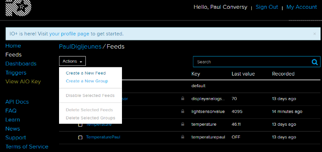
Étape 1 - Setup an account and create a new feed on adafruit.io
Create a new feed by reaching https://io.adafruit.com/ > Feeds > Actions and then name it, for example “touchsensor”
Étape 2 - Install Arduino IDE
You will need to use Arduino IDE to code and upload the firmware onto your ESP32 board.
Download the software by visiting Arduino IDE > Scroll down until you see the “Download the Arduino IDE” section and choose the version based upon your operating system (e.g. If you have Windows 7, choose “Windows Installer” / if you have Windows 10, choose “Windows app”) > On the next page choose “Just download” and run the installation files.
Étape 3 - Prepare the ESP32 board on your computer
Follow the instructions provided on GitHub for your Operating System. For example, if you have Windows 7 or 10, choose “Instructions for Windows” / if you have a MacBook, choose “Instructions for Mac”
For the “Instructions for Windows” section, you can ignore the following step:
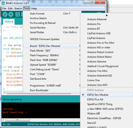
Étape 4 - Check that the board is correctly configured
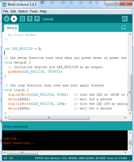
Launch Arduino IDE and select “ESP32 Dev Module” from the Tools menu > Board.
Fetch the Blink example from File > Examples > 01.Basics > Blink.
write int LED_BUILTIN = 2; at the top of the code
/*
ESP 32 Blink
Turns on an LED on for one second, then off for one second, repeatedly.
The ESP32 has an internal blue LED at D2 (GPIO 02)
*/
int LED_BUILTIN = 2;
void setup()
{
pinMode(LED_BUILTIN, OUTPUT);
}
void loop()
{
digitalWrite(LED_BUILTIN, HIGH); // turn the LED on (HIGH is the voltage level)
delay(1000); // wait for a second
digitalWrite(LED_BUILTIN, LOW); // turn the LED off by making the voltage LOW
delay(1000); // wait for a second
}
Finally, upload the code by using the right arrow (→) button at the top right corner of the window, by choosing Sketch > Upload or by pressing Ctrl+U on the keyboard.
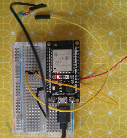
Étape 5 - Wiring the LED and the touch sensor to the ESP32
We will connect an LED to the board so that we will know when the tail actually gets touched.
Connect a male/female jumper wire to D4 on the board. D4 is by default connected to the internal touch sensor.
Connect D2 (by default connected to the board’s internal LED) to the positive leg of the external LED, using a male to female jumper wire.
Connect the negative leg of the LED to GND on the board, using a male/female jumper wire.
If needed, use some tape to secure the jumper wires to the LED.
Étape 6 - Place the electronic board inside the pet
The wooden pet needs to be laser cut. You can download the cutting pattern for laser cutter from here.
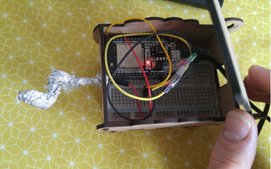
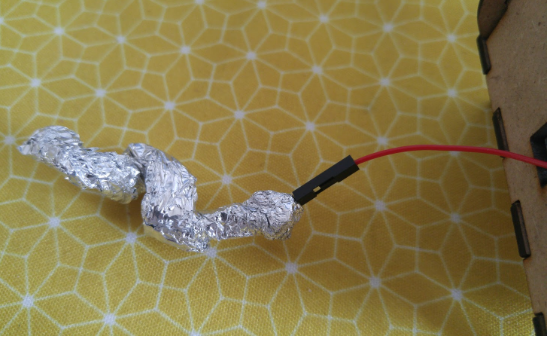
Place all the parts inside the pet, and connect the internal touch sensor to the aluminum tail.
Étape 7 - Programming on tuniot
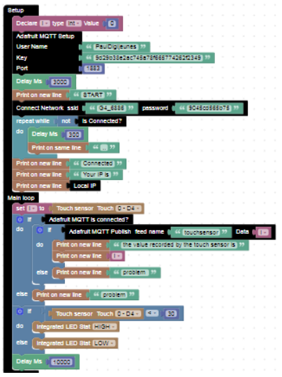
Let’s create a program that registers the values recorded by the touch sensor and publishes them online.
For that we need to reach: http://easycoding.tn/esp32/demos/code/
Choose the appropriate blocks to create the code displayed below.
Complete the fields “ssid” and “password” with the name of your wifiwi-fi connection and its password respectively.
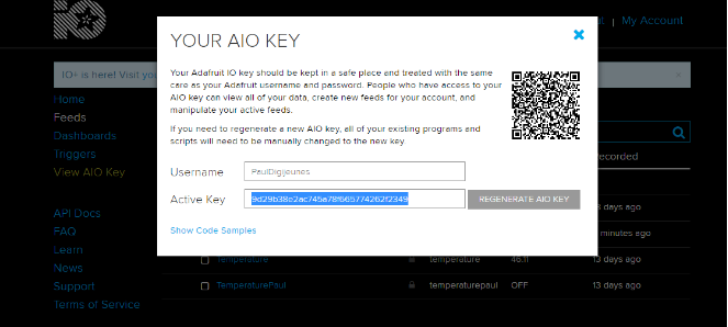
The “User Name” and “Key” are available here (just click on View AIO Key).
Étape 8 - Install Adafruit_MQTT.h and Adafruit_MQTT_Client.h libraries on Arduino IDE
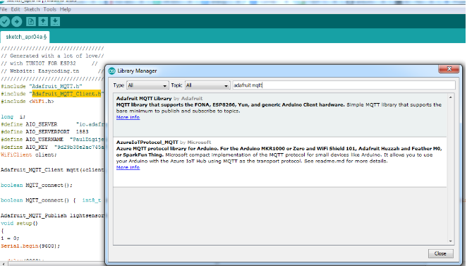
For that we need to run Arduino IDE and go to Sketch > Include Library > Manage Libraries… > Search for “Adafruit mqtt library” and install the first result.
Étape 9 - Programming on Arduino IDE
To upload the code on Arduino IDE, click on the “Copy Arduino code into clipboard” button.
then paste the code onto Arduino IDE, and upload it to the ESP32.
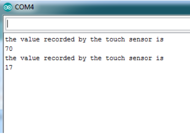
If you click on Serial Monitor (top right of the Arduino IDE screen, below the “X” button), you should see the values recorded by the touch sensor.
It means that your ESP32 is connected to the internet, and that it’s sending the value recorded by the internal touch sensor on-line, on https://adafruit.io.
Étape 10 - Create an applet on IFTTT
For this we need to access https://ifttt.com/ and create an account.
Then, click on My Applets.
Choose New Applet
Click on THIS
Search for Adafruit
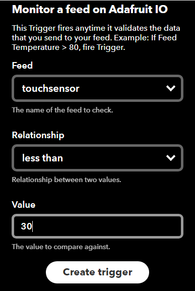
Choose Monitor a feed on Adafruit IO
Configure it as follows
And Click on Create trigger
Click on THAT
Choose Facebook
Choose Create a status message
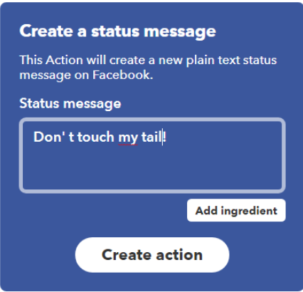
Type your message and click on Create action.
In this case, the message that will be posted on your facebook timeline is “Don’t touch my tail!”.
Notes et références
This tutorial has been developed as part of the iTech project, co-financed by the Erasmus + Programme of the European Union.
For more details, contact info@digijeunes.com
Published





 Français
 English
 Deutsch
 Español
 Italiano
 Português