(Imported page from en.wikifab.org) |
(convert properties for internationnalized Wikifab) |
||
| Ligne 1 : | Ligne 1 : | ||
| − | {{Tuto Details | + | {{ {{tntn|Tuto Details}} |
|SourceLanguage=en | |SourceLanguage=en | ||
|Language=en | |Language=en | ||
| Ligne 5 : | Ligne 5 : | ||
|Type=Creation | |Type=Creation | ||
|Area=Energy | |Area=Energy | ||
| − | |Description=This is the second tutorial for building the solar concentrator of Open Source Ecologie (French branch of Open Source Ecology). Here we are going to build the mirror facets. | + | |Description=<translate>This is the second tutorial for building the solar concentrator of Open Source Ecologie (French branch of Open Source Ecology). Here we are going to build the mirror facets.</translate> |
|Difficulty=Medium | |Difficulty=Medium | ||
|Cost=100 | |Cost=100 | ||
| Ligne 14 : | Ligne 14 : | ||
|Main_Picture=SolarOSE_G2_7_4.jpg | |Main_Picture=SolarOSE_G2_7_4.jpg | ||
}} | }} | ||
| − | {{Introduction}} | + | {{ {{tntn|Introduction}}|}} |
{{Separator}} | {{Separator}} | ||
| − | {{Materials | + | {{ {{tntn|Materials}} |
| − | |Material=- Square tube made of aluminum | + | |Material=<translate>- Square tube made of aluminum |
- Stainless steel bar | - Stainless steel bar | ||
- Wood board | - Wood board | ||
| − | - Mirror sheet | + | - Mirror sheet</translate> |
|Step_Picture_00=No-image-yet.jpg | |Step_Picture_00=No-image-yet.jpg | ||
|Step_Picture_01=No-image-yet.jpg | |Step_Picture_01=No-image-yet.jpg | ||
| Ligne 29 : | Ligne 29 : | ||
}} | }} | ||
{{Separator}} | {{Separator}} | ||
| − | {{Tuto Step | + | {{ {{tntn|Tuto Step}} |
| − | |Step_Title=Setting up the square tubes | + | |Step_Title=<translate>Setting up the square tubes</translate> |
| − | |Step_Content=Cut to a length of 2000 mm the aluminum tubes of 40x20 mm (or buy them with these dimensions). Drill a hole of 5 mm centered on the width, at 100 mm from each extremity. Tap (thread) this hole, made for a screw with a diameter of 6 mm (M6). | + | |Step_Content=<translate>Cut to a length of 2000 mm the aluminum tubes of 40x20 mm (or buy them with these dimensions). Drill a hole of 5 mm centered on the width, at 100 mm from each extremity. Tap (thread) this hole, made for a screw with a diameter of 6 mm (M6).</translate> |
|Step_Picture_00=SolarOSE_G2_1_1.jpg | |Step_Picture_00=SolarOSE_G2_1_1.jpg | ||
|Step_Picture_01=No-image-yet.jpg | |Step_Picture_01=No-image-yet.jpg | ||
| Ligne 39 : | Ligne 39 : | ||
|Step_Picture_05=No-image-yet.jpg | |Step_Picture_05=No-image-yet.jpg | ||
}} | }} | ||
| − | {{Tuto Step | + | {{ {{tntn|Tuto Step}} |
| − | |Step_Title=Preparation of the axes | + | |Step_Title=<translate>Preparation of the axes</translate> |
| − | |Step_Content=Cut 40 bars with a diameter of 8 mm and a length of 200 mm. Make a flat spot at 147 mm from the bar’s extremity; the flat spot will be positioned to the exterior of the aluminum tube. | + | |Step_Content=<translate>Cut 40 bars with a diameter of 8 mm and a length of 200 mm. Make a flat spot at 147 mm from the bar’s extremity; the flat spot will be positioned to the exterior of the aluminum tube.</translate> |
|Step_Picture_00=SolarOSE_G2_2_1.jpg | |Step_Picture_00=SolarOSE_G2_2_1.jpg | ||
|Step_Picture_01=SolarOSE_G2_2_2.jpg | |Step_Picture_01=SolarOSE_G2_2_2.jpg | ||
| Ligne 49 : | Ligne 49 : | ||
|Step_Picture_05=No-image-yet.jpg | |Step_Picture_05=No-image-yet.jpg | ||
}} | }} | ||
| − | {{Tuto Step | + | {{ {{tntn|Tuto Step}} |
| − | |Step_Title=Preparation of the supports for the axes | + | |Step_Title=<translate>Preparation of the supports for the axes</translate> |
| − | |Step_Content=Choose a wood board having a thickness of 100 mm, use the laser cutter to make 40 interior holds (rounded edges) and 40 exterior holds (straight edges), according to the cutting file. | + | |Step_Content=<translate>Choose a wood board having a thickness of 100 mm, use the laser cutter to make 40 interior holds (rounded edges) and 40 exterior holds (straight edges), according to the cutting file.</translate> |
|Step_Picture_00=No-image-yet.jpg | |Step_Picture_00=No-image-yet.jpg | ||
|Step_Picture_01=No-image-yet.jpg | |Step_Picture_01=No-image-yet.jpg | ||
| Ligne 59 : | Ligne 59 : | ||
|Step_Picture_05=No-image-yet.jpg | |Step_Picture_05=No-image-yet.jpg | ||
}} | }} | ||
| − | {{Tuto Step | + | {{ {{tntn|Tuto Step}} |
| − | |Step_Title=Preparation of the mirror facets | + | |Step_Title=<translate>Preparation of the mirror facets</translate> |
| − | |Step_Content=With a cutter or a plunging saw, cut strips of 2000 mm long and 100 mm large from the plate of mirrors. If the plate doesn’t have the right length, two flats of 1000 mm long are cut to cover each part of the mirror. It’s important not to damage the mirror, in order to keep the faces of the mirror plane. For example, a deviation of 0,1° generates a misalignment of 1 cm on the receiver. | + | |Step_Content=<translate>With a cutter or a plunging saw, cut strips of 2000 mm long and 100 mm large from the plate of mirrors. If the plate doesn’t have the right length, two flats of 1000 mm long are cut to cover each part of the mirror. It’s important not to damage the mirror, in order to keep the faces of the mirror plane. For example, a deviation of 0,1° generates a misalignment of 1 cm on the receiver.</translate> |
|Step_Picture_00=SolarOSE_G2_3_1.jpg | |Step_Picture_00=SolarOSE_G2_3_1.jpg | ||
|Step_Picture_01=SolarOSE_G2_3_2.jpg | |Step_Picture_01=SolarOSE_G2_3_2.jpg | ||
| Ligne 69 : | Ligne 69 : | ||
|Step_Picture_05=No-image-yet.jpg | |Step_Picture_05=No-image-yet.jpg | ||
}} | }} | ||
| − | {{Tuto Step | + | {{ {{tntn|Tuto Step}} |
| − | |Step_Title=Assembling of the axes | + | |Step_Title=<translate>Assembling of the axes</translate> |
| − | |Step_Content=The 40 bars are the axes; for all of them, insert a hold close to the flat spot; this part will be on the extremity that will enter firstly in the square tubes. Insert a second hold, 47 mm from the other extremity of the bar. Put the bar assembled with the two holds on a plane zone, with the bar in the lower part, to ensure that the holds are parallel between them. In this position, orientate the flat spot to the upper part (photo). Glue the holds with araldite type glue. | + | |Step_Content=<translate>The 40 bars are the axes; for all of them, insert a hold close to the flat spot; this part will be on the extremity that will enter firstly in the square tubes. Insert a second hold, 47 mm from the other extremity of the bar. Put the bar assembled with the two holds on a plane zone, with the bar in the lower part, to ensure that the holds are parallel between them. In this position, orientate the flat spot to the upper part (photo). Glue the holds with araldite type glue.</translate> |
|Step_Picture_00=SolarOSE_G2_4_1.jpg | |Step_Picture_00=SolarOSE_G2_4_1.jpg | ||
|Step_Picture_01=SolarOSE_G2_4_2.jpg | |Step_Picture_01=SolarOSE_G2_4_2.jpg | ||
| Ligne 79 : | Ligne 79 : | ||
|Step_Picture_05=No-image-yet.jpg | |Step_Picture_05=No-image-yet.jpg | ||
}} | }} | ||
| − | {{Tuto Step | + | {{ {{tntn|Tuto Step}} |
| − | |Step_Title=Assembling of the mirror facets | + | |Step_Title=<translate>Assembling of the mirror facets</translate> |
| − | |Step_Content=Insert the bars with the holds on them in the aluminum tubes. The bar must be tangent on the opposite side to the drilled hole. In this way, the plat spot is in front of the hole. Turn the screw in the drilled hole until it fixes the bar on the plat spot. The bar is fixed laterally with the holds and it is fixed in height on its entire length with the screw. | + | |Step_Content=<translate>Insert the bars with the holds on them in the aluminum tubes. The bar must be tangent on the opposite side to the drilled hole. In this way, the plat spot is in front of the hole. Turn the screw in the drilled hole until it fixes the bar on the plat spot. The bar is fixed laterally with the holds and it is fixed in height on its entire length with the screw. |
| − | Glue the rectangular mirror facets on the aluminum tubes. Make sure that they are centered on the width of the tubes. | + | Glue the rectangular mirror facets on the aluminum tubes. Make sure that they are centered on the width of the tubes.</translate> |
|Step_Picture_00=No-image-yet.jpg | |Step_Picture_00=No-image-yet.jpg | ||
|Step_Picture_01=No-image-yet.jpg | |Step_Picture_01=No-image-yet.jpg | ||
| Ligne 91 : | Ligne 91 : | ||
|Step_Picture_05=No-image-yet.jpg | |Step_Picture_05=No-image-yet.jpg | ||
}} | }} | ||
| − | {{Tuto Step | + | {{ {{tntn|Tuto Step}} |
| − | |Step_Title=Mounting of the mirror facets on the support frames | + | |Step_Title=<translate>Mounting of the mirror facets on the support frames</translate> |
| − | |Step_Content=Mount the facets on the frames by passing the axes in the holes of the wood supports using autolubrifying bearings. | + | |Step_Content=<translate>Mount the facets on the frames by passing the axes in the holes of the wood supports using autolubrifying bearings.</translate> |
|Step_Picture_00=SolarOSE_G2_7_1.jpg | |Step_Picture_00=SolarOSE_G2_7_1.jpg | ||
|Step_Picture_01=SolarOSE_G2_7_2.jpg | |Step_Picture_01=SolarOSE_G2_7_2.jpg | ||
| Ligne 101 : | Ligne 101 : | ||
|Step_Picture_05=No-image-yet.jpg | |Step_Picture_05=No-image-yet.jpg | ||
}} | }} | ||
| − | {{Tuto Step | + | {{ {{tntn|Tuto Step}} |
| − | |Step_Title=Possible improvements | + | |Step_Title=<translate>Possible improvements</translate> |
| − | |Step_Content=Add a diagonally tube to the squared structure, in order to prevent the deformable movements. The mirror facets added on the squared aluminum tubes of 40x20 mm is an improved solution. The first solution, a half PVC tube (building them took 10 hours). Cut in half 10 PVC tubes on their length (a template should help cutting correctly the tube), the result is 20 mirror supports. Cut 6 wood pieces in shape of half-disc for each mirror face, with a hole in order to add the motor’s axe. The axe is maintained by two wood pieces at each extremity. Another two wood pieces reinforce the structure and maintain the mirrors. The mirror strips with a width of 100 mm are collected on the surface of the half PVC tubes and they are leaning on the 6 wood pieces. The issue is the low torsion resistance of the mirror face; the reflected light will not be collected on the same line, lowering the optic performances. | + | |Step_Content=<translate>Add a diagonally tube to the squared structure, in order to prevent the deformable movements. The mirror facets added on the squared aluminum tubes of 40x20 mm is an improved solution. The first solution, a half PVC tube (building them took 10 hours). Cut in half 10 PVC tubes on their length (a template should help cutting correctly the tube), the result is 20 mirror supports. Cut 6 wood pieces in shape of half-disc for each mirror face, with a hole in order to add the motor’s axe. The axe is maintained by two wood pieces at each extremity. Another two wood pieces reinforce the structure and maintain the mirrors. The mirror strips with a width of 100 mm are collected on the surface of the half PVC tubes and they are leaning on the 6 wood pieces. The issue is the low torsion resistance of the mirror face; the reflected light will not be collected on the same line, lowering the optic performances.</translate> |
|Step_Picture_00=No-image-yet.jpg | |Step_Picture_00=No-image-yet.jpg | ||
|Step_Picture_01=No-image-yet.jpg | |Step_Picture_01=No-image-yet.jpg | ||
| Ligne 111 : | Ligne 111 : | ||
|Step_Picture_05=No-image-yet.jpg | |Step_Picture_05=No-image-yet.jpg | ||
}} | }} | ||
| − | {{Notes}} | + | {{ {{tntn|Notes}}|}} |
Version du 11 août 2017 à 10:13
Sommaire
- 1 Étape 1 - Setting up the square tubes
- 2 Étape 2 - Preparation of the axes
- 3 Étape 3 - Preparation of the supports for the axes
- 4 Étape 4 - Preparation of the mirror facets
- 5 Étape 5 - Assembling of the axes
- 6 Étape 6 - Assembling of the mirror facets
- 7 Étape 7 - Mounting of the mirror facets on the support frames
- 8 Étape 8 - Possible improvements
- 9 Commentaires
Étape 1 - Setting up the square tubes
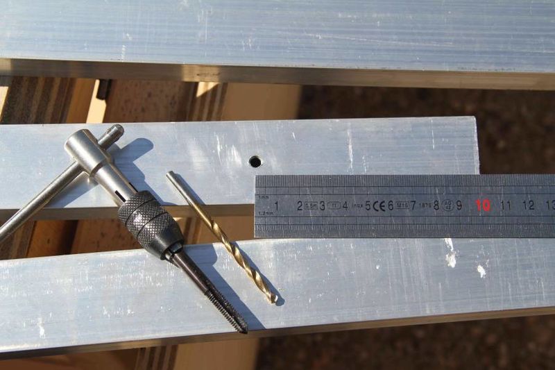
Cut to a length of 2000 mm the aluminum tubes of 40x20 mm (or buy them with these dimensions). Drill a hole of 5 mm centered on the width, at 100 mm from each extremity. Tap (thread) this hole, made for a screw with a diameter of 6 mm (M6).
Étape 2 - Preparation of the axes
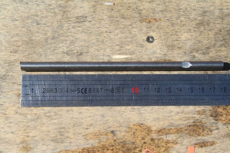
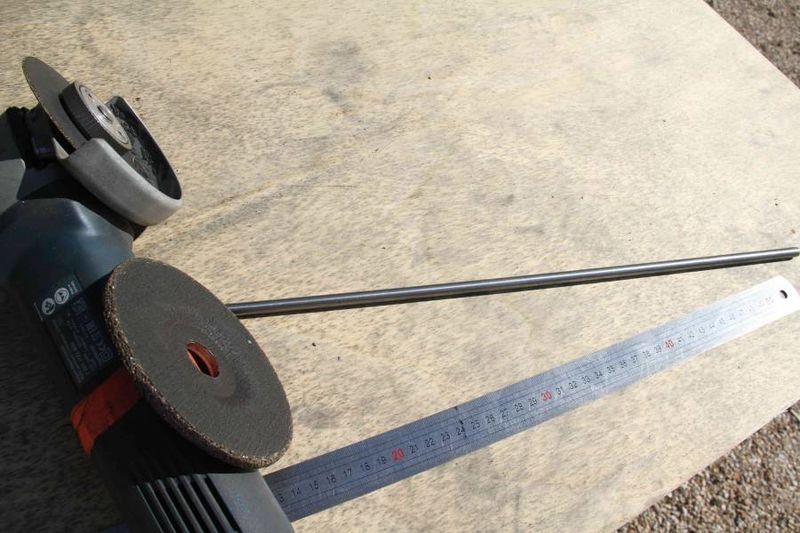
Cut 40 bars with a diameter of 8 mm and a length of 200 mm. Make a flat spot at 147 mm from the bar’s extremity; the flat spot will be positioned to the exterior of the aluminum tube.
Étape 3 - Preparation of the supports for the axes
Choose a wood board having a thickness of 100 mm, use the laser cutter to make 40 interior holds (rounded edges) and 40 exterior holds (straight edges), according to the cutting file.
Étape 4 - Preparation of the mirror facets
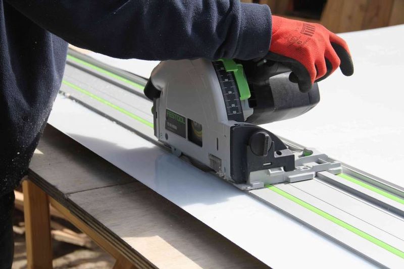
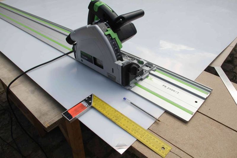
With a cutter or a plunging saw, cut strips of 2000 mm long and 100 mm large from the plate of mirrors. If the plate doesn’t have the right length, two flats of 1000 mm long are cut to cover each part of the mirror. It’s important not to damage the mirror, in order to keep the faces of the mirror plane. For example, a deviation of 0,1° generates a misalignment of 1 cm on the receiver.
Étape 5 - Assembling of the axes
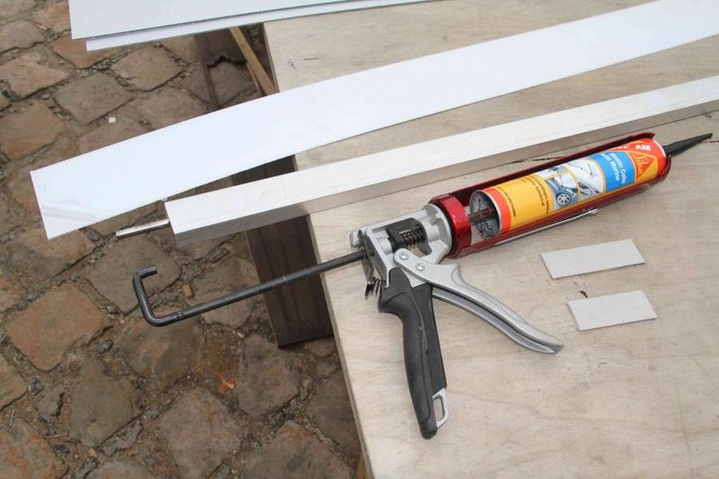
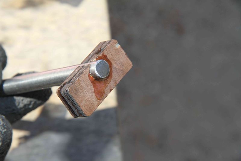
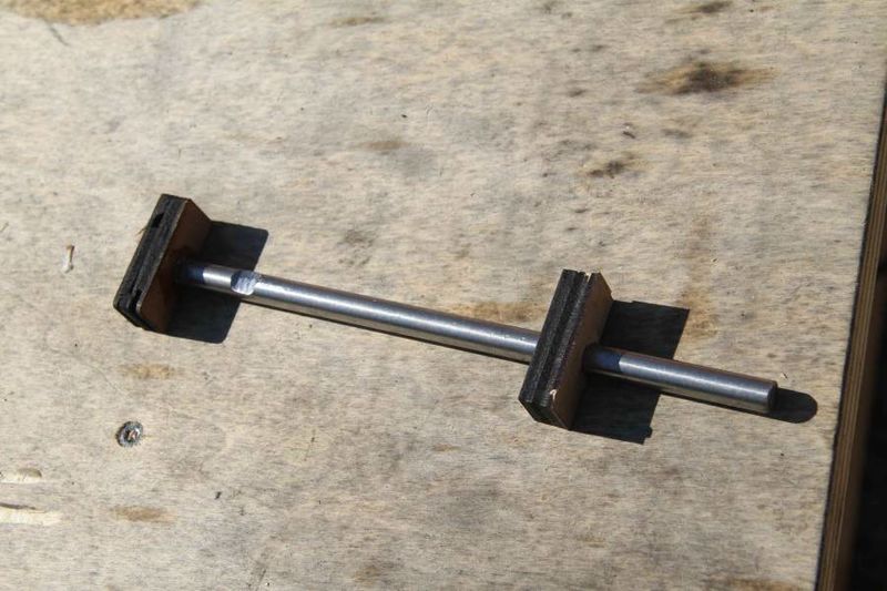
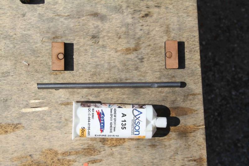
The 40 bars are the axes; for all of them, insert a hold close to the flat spot; this part will be on the extremity that will enter firstly in the square tubes. Insert a second hold, 47 mm from the other extremity of the bar. Put the bar assembled with the two holds on a plane zone, with the bar in the lower part, to ensure that the holds are parallel between them. In this position, orientate the flat spot to the upper part (photo). Glue the holds with araldite type glue.
Étape 6 - Assembling of the mirror facets
Insert the bars with the holds on them in the aluminum tubes. The bar must be tangent on the opposite side to the drilled hole. In this way, the plat spot is in front of the hole. Turn the screw in the drilled hole until it fixes the bar on the plat spot. The bar is fixed laterally with the holds and it is fixed in height on its entire length with the screw.
Glue the rectangular mirror facets on the aluminum tubes. Make sure that they are centered on the width of the tubes.
Étape 7 - Mounting of the mirror facets on the support frames
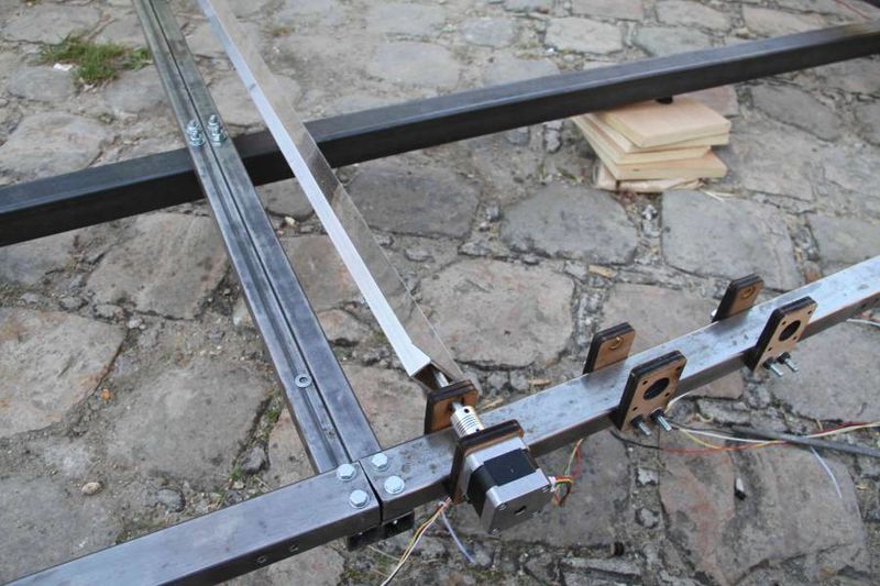
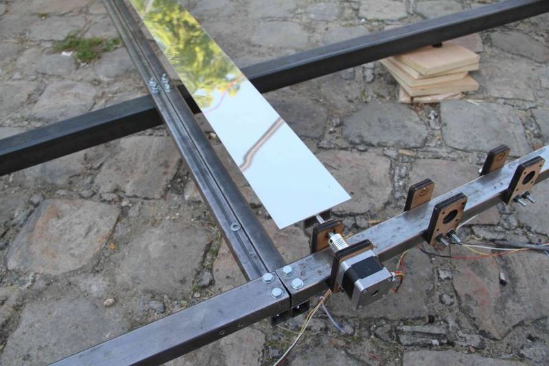
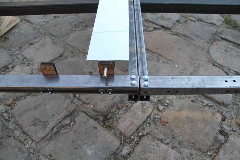
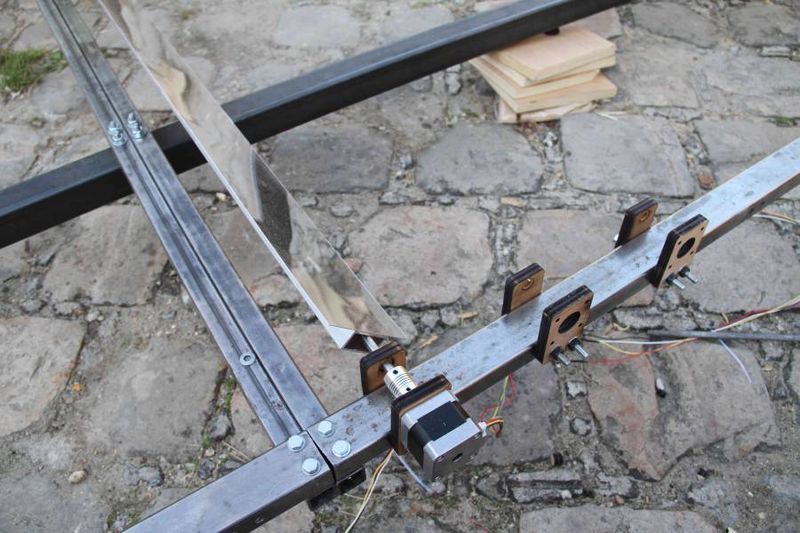
Mount the facets on the frames by passing the axes in the holes of the wood supports using autolubrifying bearings.
Étape 8 - Possible improvements
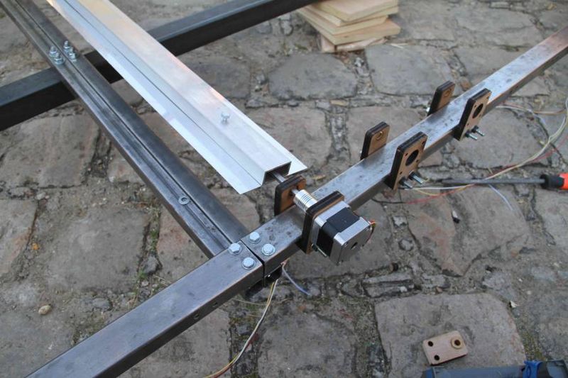
Add a diagonally tube to the squared structure, in order to prevent the deformable movements. The mirror facets added on the squared aluminum tubes of 40x20 mm is an improved solution. The first solution, a half PVC tube (building them took 10 hours). Cut in half 10 PVC tubes on their length (a template should help cutting correctly the tube), the result is 20 mirror supports. Cut 6 wood pieces in shape of half-disc for each mirror face, with a hole in order to add the motor’s axe. The axe is maintained by two wood pieces at each extremity. Another two wood pieces reinforce the structure and maintain the mirrors. The mirror strips with a width of 100 mm are collected on the surface of the half PVC tubes and they are leaning on the 6 wood pieces. The issue is the low torsion resistance of the mirror face; the reflected light will not be collected on the same line, lowering the optic performances.

 Français
 English
 Deutsch
 Español
 Italiano
 Português