(set pageLanguageSource property) |
(update property name) |
||
| (3 révisions intermédiaires par un autre utilisateur non affichées) | |||
| Ligne 1 : | Ligne 1 : | ||
| − | {{ | + | {{Tuto Details |
|SourceLanguage=none | |SourceLanguage=none | ||
|Language=en | |Language=en | ||
| Ligne 14 : | Ligne 14 : | ||
|Main_Picture=PiKon_telescope_PiKon_Final.jpg | |Main_Picture=PiKon_telescope_PiKon_Final.jpg | ||
}} | }} | ||
| − | {{ | + | {{Introduction |
|Introduction=The PiKon telescope consists of two main assemblies: the Mirror Assembly and the Spider Assembly. The telescope is mounted onto an astronomical dovetail wedge. There is photographic standard 1⁄4” Whitworth thread for mounting on an astronomical or photographic tripod. | |Introduction=The PiKon telescope consists of two main assemblies: the Mirror Assembly and the Spider Assembly. The telescope is mounted onto an astronomical dovetail wedge. There is photographic standard 1⁄4” Whitworth thread for mounting on an astronomical or photographic tripod. | ||
Images are captured by the Raspberry Pi Camera and Computer. The Raspberry Pi is used in “command mode” and details of syntax are included later. Images can me transferred to PC or Mac from the Pi’s micro-SD card or via a Dropbox (or similar) from the Pi with internet connection. | Images are captured by the Raspberry Pi Camera and Computer. The Raspberry Pi is used in “command mode” and details of syntax are included later. Images can me transferred to PC or Mac from the Pi’s micro-SD card or via a Dropbox (or similar) from the Pi with internet connection. | ||
}} | }} | ||
| − | {{ | + | {{Materials |
|Material='''Parts to print:''' | |Material='''Parts to print:''' | ||
| Ligne 61 : | Ligne 61 : | ||
}} | }} | ||
{{Separator}} | {{Separator}} | ||
| − | {{ | + | {{Tuto Step |
|Step_Title=General Precautions – What could possibly go wrong!? | |Step_Title=General Precautions – What could possibly go wrong!? | ||
|Step_Content=The PiKon telescope is a robust design but there are two issues that need care if you are to get the most out of your project. | |Step_Content=The PiKon telescope is a robust design but there are two issues that need care if you are to get the most out of your project. | ||
| Ligne 73 : | Ligne 73 : | ||
As with all reflecting telescopes, care must be taken to avoid damaging the mirror. When assembling or modifying the telescope be careful not to let components drop down the Telescope Tube onto the Mirror. | As with all reflecting telescopes, care must be taken to avoid damaging the mirror. When assembling or modifying the telescope be careful not to let components drop down the Telescope Tube onto the Mirror. | ||
}} | }} | ||
| − | {{ | + | {{Tuto Step |
|Step_Title=Mirror Assembly | |Step_Title=Mirror Assembly | ||
| − | |Step_Content={{ | + | |Step_Content={{Warning|Do not attach the Mirror to the Mirror Mount with the double-sided tape pad until the Mirror Assembly has been assembled.}} |
The Mirror Mount and the Mirror Base are first connected together by placing three 8mm nuts through the Mirror Base. The three springs are then threaded onto the shaft of the bolts before the Mirror Mount is placed on the bolts and fastened by three 8mm nuts that are captured by hexagonal holes in the Mirror Mount. The Mirror Mount should be placed so that the hexagonal holes are facing away from the Mirror Base with the nuts visible after assembly. | The Mirror Mount and the Mirror Base are first connected together by placing three 8mm nuts through the Mirror Base. The three springs are then threaded onto the shaft of the bolts before the Mirror Mount is placed on the bolts and fastened by three 8mm nuts that are captured by hexagonal holes in the Mirror Mount. The Mirror Mount should be placed so that the hexagonal holes are facing away from the Mirror Base with the nuts visible after assembly. | ||
| Ligne 85 : | Ligne 85 : | ||
|Step_Picture_05=PiKon_telescope_Step1f.png | |Step_Picture_05=PiKon_telescope_Step1f.png | ||
}} | }} | ||
| − | {{ | + | {{Tuto Step |
|Step_Title=Attach the Mirror to the Mirror Mount. | |Step_Title=Attach the Mirror to the Mirror Mount. | ||
|Step_Content=The double-sided tape pad may then be stuck to the surface of the Mirror Mount and trimmed to size with a sharp knife. | |Step_Content=The double-sided tape pad may then be stuck to the surface of the Mirror Mount and trimmed to size with a sharp knife. | ||
| Ligne 93 : | Ligne 93 : | ||
The Mirror alignment may then be adjusted by rotating the 3 bolts. Ensure that the gap between the Mirror Base and the Mirror Mount is the same near all three bolts. This can be done by using a drill bit as a guage. | The Mirror alignment may then be adjusted by rotating the 3 bolts. Ensure that the gap between the Mirror Base and the Mirror Mount is the same near all three bolts. This can be done by using a drill bit as a guage. | ||
| − | {{Info| | + | {{Info|The mirror used in the kit is a 41⁄2 inch, 113 mm spherical, focal length 600mm. Spherical or parabolic mirrors can be used. Mirrors of different focal lengths may be used, but the length of the Telescope Tube will need to be cut to length accordingly.}} |
|Step_Picture_00=PiKon_telescope_Step2a.png | |Step_Picture_00=PiKon_telescope_Step2a.png | ||
|Step_Picture_01=PiKon_telescope_Step2b.png | |Step_Picture_01=PiKon_telescope_Step2b.png | ||
| Ligne 101 : | Ligne 101 : | ||
|Step_Picture_05=PiKon_telescope_Step2f.png | |Step_Picture_05=PiKon_telescope_Step2f.png | ||
}} | }} | ||
| − | {{ | + | {{Tuto Step |
|Step_Title=Pi Camera mounting | |Step_Title=Pi Camera mounting | ||
|Step_Content=The Spider Assembly provides support for the Pi camera on the axis of the telescope and a method of moving the camera backwards and forwards along the telescope axis to allow focusing. | |Step_Content=The Spider Assembly provides support for the Pi camera on the axis of the telescope and a method of moving the camera backwards and forwards along the telescope axis to allow focusing. | ||
| Ligne 107 : | Ligne 107 : | ||
The Pi Camera is mounted on the camera mount which already has a rubber gear rack attached. The first step is to prepare the Pi camera by removing the camera lens to expose the sensor. The lens unscrews from the camera body, but is set in place by a “Loctite” type sealant. Some force may be needed to initially break the seal to unscrew the lens. It is advised that the camera body be held as shown during this step. After separation the lens may be discarded. | The Pi Camera is mounted on the camera mount which already has a rubber gear rack attached. The first step is to prepare the Pi camera by removing the camera lens to expose the sensor. The lens unscrews from the camera body, but is set in place by a “Loctite” type sealant. Some force may be needed to initially break the seal to unscrew the lens. It is advised that the camera body be held as shown during this step. After separation the lens may be discarded. | ||
| − | {{Info| | + | {{Info|It is also possible for the ribbon cable which connects the camera to the camera printed circuit board (PCB) to become disconnected during lens removal and it is worth checking that the ribbon cable is plugged into the PCB.}} |
Print your own builders please note: The Camera Mount requires a T 2.5 Timing belt which is adhered to the shaft with super glue. The belt is supplied with the print your own kit. | Print your own builders please note: The Camera Mount requires a T 2.5 Timing belt which is adhered to the shaft with super glue. The belt is supplied with the print your own kit. | ||
| Ligne 114 : | Ligne 114 : | ||
The Pi Camera is then attached to the Camera Mount by 4 x 2mm nuts and bolts. | The Pi Camera is then attached to the Camera Mount by 4 x 2mm nuts and bolts. | ||
| − | {{Info| | + | {{Info|bolts supplied may be shorter than those shown in the photograph}} |
|Step_Picture_00=PiKon_telescope_Step3a.png | |Step_Picture_00=PiKon_telescope_Step3a.png | ||
|Step_Picture_01=PiKon_telescope_Step3b.png | |Step_Picture_01=PiKon_telescope_Step3b.png | ||
| Ligne 121 : | Ligne 121 : | ||
|Step_Picture_04=PiKon_telescope_Step3e.png | |Step_Picture_04=PiKon_telescope_Step3e.png | ||
}} | }} | ||
| − | {{ | + | {{Tuto Step |
|Step_Content=The focus mechanism is assembled next. This consists of a cog connected to a screw threaded shaft and a Focus Knob attached to the threaded shaft by two locking square nuts and a lock nut. | |Step_Content=The focus mechanism is assembled next. This consists of a cog connected to a screw threaded shaft and a Focus Knob attached to the threaded shaft by two locking square nuts and a lock nut. | ||
| Ligne 129 : | Ligne 129 : | ||
|Step_Picture_02=PiKon_telescope_Step4c.png | |Step_Picture_02=PiKon_telescope_Step4c.png | ||
}} | }} | ||
| − | {{ | + | {{Tuto Step |
|Step_Title=Focus Knob | |Step_Title=Focus Knob | ||
|Step_Content=The focus knob is attached by placing the square recess in the knob over two locking square nuts and holding it in place with a lock nut. Position the first nut on the treaded shaft and turn, checking with the depth of the Focus Knob so that there is enough length of shaft above the first nut to place the Focus Knob and lock nut. Then attach the second square nut and lock the two nuts together. Place the Focus Knob over the Threaded Shaft and engage the square recess in the Focus Knob. | |Step_Content=The focus knob is attached by placing the square recess in the knob over two locking square nuts and holding it in place with a lock nut. Position the first nut on the treaded shaft and turn, checking with the depth of the Focus Knob so that there is enough length of shaft above the first nut to place the Focus Knob and lock nut. Then attach the second square nut and lock the two nuts together. Place the Focus Knob over the Threaded Shaft and engage the square recess in the Focus Knob. | ||
| Ligne 136 : | Ligne 136 : | ||
|Step_Picture_02=PiKon_telescope_Step5c.png | |Step_Picture_02=PiKon_telescope_Step5c.png | ||
}} | }} | ||
| − | {{ | + | {{Tuto Step |
|Step_Title=Focus Knob | |Step_Title=Focus Knob | ||
|Step_Content=Finally, secure the Focus Knob in place with the lock nut. | |Step_Content=Finally, secure the Focus Knob in place with the lock nut. | ||
|Step_Picture_00=PiKon_telescope_Step6.png | |Step_Picture_00=PiKon_telescope_Step6.png | ||
}} | }} | ||
| − | {{ | + | {{Tuto Step |
|Step_Title=Raspberry Pi case | |Step_Title=Raspberry Pi case | ||
|Step_Content=The Raspberry Pi case will be attached to the Spider by the Raspberry Pi mount and a single self-tapping screw. A hole should be | |Step_Content=The Raspberry Pi case will be attached to the Spider by the Raspberry Pi mount and a single self-tapping screw. A hole should be | ||
| Ligne 150 : | Ligne 150 : | ||
|Step_Picture_03=PiKon_telescope_Step7d.png | |Step_Picture_03=PiKon_telescope_Step7d.png | ||
}} | }} | ||
| − | {{ | + | {{Tuto Step |
|Step_Title=Self-tapping screw will tap | |Step_Title=Self-tapping screw will tap | ||
|Step_Content=A 2.5 mm is made in the Spider circumference the 3.5mm self-tapping screw will tap. The hole is made over one of the legs of the spider so that the self- tapping screw does not protrude. | |Step_Content=A 2.5 mm is made in the Spider circumference the 3.5mm self-tapping screw will tap. The hole is made over one of the legs of the spider so that the self- tapping screw does not protrude. | ||
| − | {{Info| | + | {{Info|During image capture a red LED on the Raspberry Pi Camera printed circuit board is illuminated. On kits with cameras supplied, this LED has been painted out with a removable paint.}} |
|Step_Picture_00=PiKon_telescope_Step8a.png | |Step_Picture_00=PiKon_telescope_Step8a.png | ||
|Step_Picture_01=PiKon_telescope_Step8b.png | |Step_Picture_01=PiKon_telescope_Step8b.png | ||
| Ligne 161 : | Ligne 161 : | ||
|Step_Picture_04=PiKon_telescope_Step8e.png | |Step_Picture_04=PiKon_telescope_Step8e.png | ||
}} | }} | ||
| − | {{ | + | {{Tuto Step |
|Step_Title=Notes for builders printing their own 3D printed components. | |Step_Title=Notes for builders printing their own 3D printed components. | ||
|Step_Content=The Raspberry Pi mount is printed in 3 parts and glued together with super glue: | |Step_Content=The Raspberry Pi mount is printed in 3 parts and glued together with super glue: | ||
| Ligne 170 : | Ligne 170 : | ||
|Step_Picture_00=PiKon_telescope_Step9.png | |Step_Picture_00=PiKon_telescope_Step9.png | ||
}} | }} | ||
| − | {{ | + | {{Tuto Step |
|Step_Title=General assembly and Tripod Mount | |Step_Title=General assembly and Tripod Mount | ||
|Step_Content=Before assembling the telescope, you may wish to improve its performance by painting the inside of the Tube with matt black paint. | |Step_Content=Before assembling the telescope, you may wish to improve its performance by painting the inside of the Tube with matt black paint. | ||
| Ligne 180 : | Ligne 180 : | ||
You may now replace the Mirror and Spider assemblies. | You may now replace the Mirror and Spider assemblies. | ||
| − | {{ | + | {{Warning|Do not fix the spider permanently to the tube until after your first trial of the PiKon so that the exact orientation of the camera can be established.}} |
The spider and Mirror Base are permanently held in place with the 3.5mm self-tapping screws provided. A 2.5mm drill is provided to drill trough the tube into the side of the Spider and Mirror Base. It is recommended that initially the spider should be secures by Gaffa tape and the orientation of the camera set on the first trial before drilling the tube. | The spider and Mirror Base are permanently held in place with the 3.5mm self-tapping screws provided. A 2.5mm drill is provided to drill trough the tube into the side of the Spider and Mirror Base. It is recommended that initially the spider should be secures by Gaffa tape and the orientation of the camera set on the first trial before drilling the tube. | ||
| Ligne 189 : | Ligne 189 : | ||
|Step_Picture_04=PiKon_telescope_Step10e.png | |Step_Picture_04=PiKon_telescope_Step10e.png | ||
}} | }} | ||
| − | {{ | + | {{Tuto Step |
|Step_Title=Notes Instructions and STL Files only customers | |Step_Title=Notes Instructions and STL Files only customers | ||
|Step_Content=The mirror used in the kit is a 41⁄2 inch, 113 mm spherical, focal length 600mm. The length of the Telescope Tube is 610mm. That is the telescope tube is just 1 cm longer than the focal length of the mirror. To determine the focal length of a third party mirrors, simply image a distant object onto a piece of paper and measure the distance between the mirror and the paper. The PiKon is designed with a long travel on the focusing rack and is forgiving of small inaccuracies in focal length measurement. Measure twice, cut once! | |Step_Content=The mirror used in the kit is a 41⁄2 inch, 113 mm spherical, focal length 600mm. The length of the Telescope Tube is 610mm. That is the telescope tube is just 1 cm longer than the focal length of the mirror. To determine the focal length of a third party mirrors, simply image a distant object onto a piece of paper and measure the distance between the mirror and the paper. The PiKon is designed with a long travel on the focusing rack and is forgiving of small inaccuracies in focal length measurement. Measure twice, cut once! | ||
}} | }} | ||
| − | {{ | + | {{Tuto Step |
|Step_Title=Setting up the Raspberry Pi | |Step_Title=Setting up the Raspberry Pi | ||
|Step_Content=The Raspberry Pi will require a power supply, USB keyboard, HDMI display and Mouse for graphic user interface (GUI). A VGA monitor may be used with a HDMI to VGA adaptor. | |Step_Content=The Raspberry Pi will require a power supply, USB keyboard, HDMI display and Mouse for graphic user interface (GUI). A VGA monitor may be used with a HDMI to VGA adaptor. | ||
| Ligne 202 : | Ligne 202 : | ||
On first use of the camera you may see an error message requesting that the camera be enabled in settings. Simply follow the instructions. | On first use of the camera you may see an error message requesting that the camera be enabled in settings. Simply follow the instructions. | ||
}} | }} | ||
| − | {{ | + | {{Tuto Step |
|Step_Title=Command Line Syntax | |Step_Title=Command Line Syntax | ||
|Step_Content=A full set of Raspberry Pi Camera commands can be found [https://www.raspberrypi.org/documentation/raspbian/applications/camera.md here]. | |Step_Content=A full set of Raspberry Pi Camera commands can be found [https://www.raspberrypi.org/documentation/raspbian/applications/camera.md here]. | ||
| Ligne 213 : | Ligne 213 : | ||
-hf ...... flips the image horizontally. The image at the camera sensor is a mirror image. | -hf ...... flips the image horizontally. The image at the camera sensor is a mirror image. | ||
}} | }} | ||
| − | {{ | + | {{Tuto Step |
|Step_Title=Setting up | |Step_Title=Setting up | ||
|Step_Content=Because the PiKon does not have an eye piece, setting up the telescope is done on screen. | |Step_Content=Because the PiKon does not have an eye piece, setting up the telescope is done on screen. | ||
| Ligne 229 : | Ligne 229 : | ||
'''Good luck and please share your experiences, images and any software that you may wish to create!''' | '''Good luck and please share your experiences, images and any software that you may wish to create!''' | ||
}} | }} | ||
| − | {{ | + | {{Notes |
|Notes=* Mirrors and parts can be obtained from our shop: http://www.pikon.online | |Notes=* Mirrors and parts can be obtained from our shop: http://www.pikon.online | ||
}} | }} | ||
| − | {{ | + | {{Tuto Status |
| − | |Complete= | + | |Complete=Published |
}} | }} | ||
Version actuelle datée du 9 décembre 2019 à 11:48
Sommaire
- 1 Introduction
- 2 Étape 1 - General Precautions – What could possibly go wrong!?
- 3 Étape 2 - Mirror Assembly
- 4 Étape 3 - Attach the Mirror to the Mirror Mount.
- 5 Étape 4 - Pi Camera mounting
- 6 Étape 5 -
- 7 Étape 6 - Focus Knob
- 8 Étape 7 - Focus Knob
- 9 Étape 8 - Raspberry Pi case
- 10 Étape 9 - Self-tapping screw will tap
- 11 Étape 10 - Notes for builders printing their own 3D printed components.
- 12 Étape 11 - General assembly and Tripod Mount
- 13 Étape 12 - Notes Instructions and STL Files only customers
- 14 Étape 13 - Setting up the Raspberry Pi
- 15 Étape 14 - Command Line Syntax
- 16 Étape 15 - Setting up
- 17 Notes et références
- 18 Commentaires
Introduction
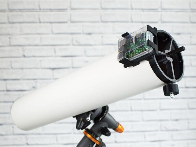
The PiKon telescope consists of two main assemblies: the Mirror Assembly and the Spider Assembly. The telescope is mounted onto an astronomical dovetail wedge. There is photographic standard 1⁄4” Whitworth thread for mounting on an astronomical or photographic tripod.
Images are captured by the Raspberry Pi Camera and Computer. The Raspberry Pi is used in “command mode” and details of syntax are included later. Images can me transferred to PC or Mac from the Pi’s micro-SD card or via a Dropbox (or similar) from the Pi with internet connection.
Matériaux
Parts to print:
- Spider (x1)
- Camera Mount (x1)
- Raspberry Pi Mount (x1)
- Focus Knob (x1)
- Mirror Mount (x1)
- Mirror Base (x1)
Other parts
- Telescope Tube (x1)
- Mirror (x1)
- 3.5 mm x 10 mm Self Tapping Screws (x1)
- 8mm Nuts (x3)
- 8mm x 25mm Bolts (x3)
- Springs (x3)
- Double Sided Tape Pad
- Raspberry Pi 2 Computer
- Raspberry Pi Camera
- Ribbon Cable
- Raspberry Pi Case
- M2 x 12mm Nylon Bolts (x4)
- M2 Nylon Nuts (x4)
- Micro SD card
- Tripod Mount
- Rubber Rack – T2.5 Timing belt
- Screw Threaded Shaft (5mm)
- 5mm Square Nuts
- 5mm Dome Nut
- Cog
- Camera adaptor
Outils
- M4 Bolts 16mm
- M4 Nuts
- 2.5mm Drill
- 4 mm Drill
- 1.5 mm Allen Key
Étape 1 - General Precautions – What could possibly go wrong!?
The PiKon telescope is a robust design but there are two issues that need care if you are to get the most out of your project.
Dust and the Camera Sensor
PiKon benefits from a very simple design that has just one optical component. The lens of the Raspberry Pi Camera is removed to allow imaging by the Optical Mirror. This means that the Raspberry Pi Camera sensor is exposed to dust and dirt. Adding sensor protection would add two optical surfaces to the design, so the sensor is left exposed. This is not a problem provided care is taken to avoid dust and dirt getting on the sensor.
Care of the Mirror
As with all reflecting telescopes, care must be taken to avoid damaging the mirror. When assembling or modifying the telescope be careful not to let components drop down the Telescope Tube onto the Mirror.
Étape 2 - Mirror Assembly
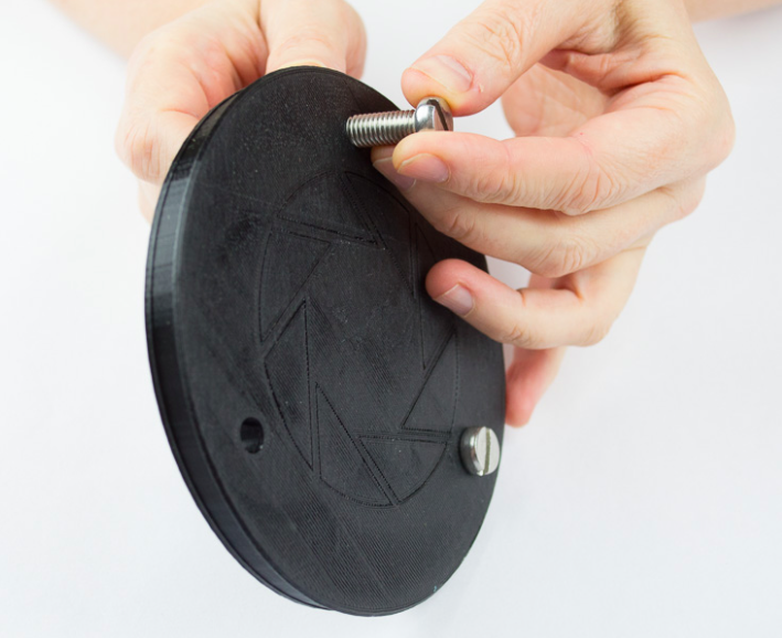
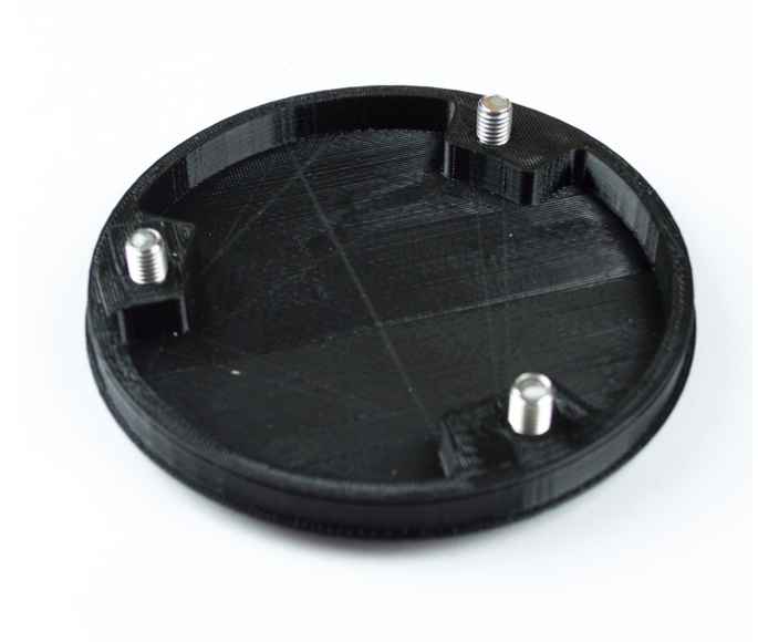
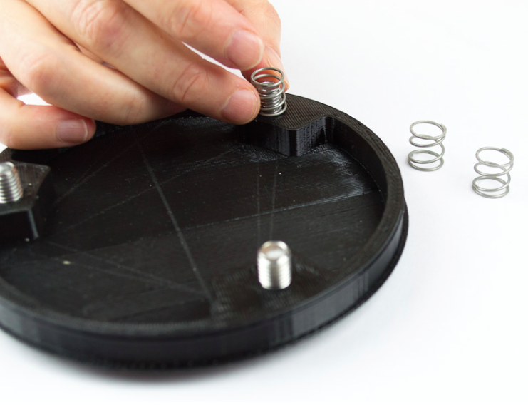
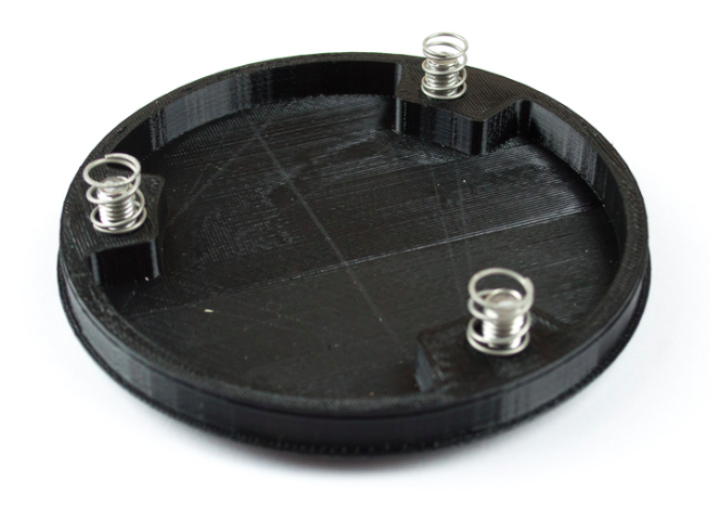
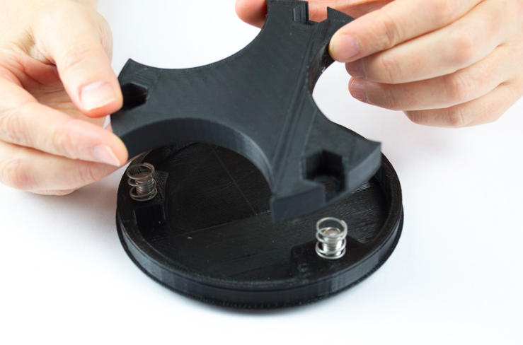
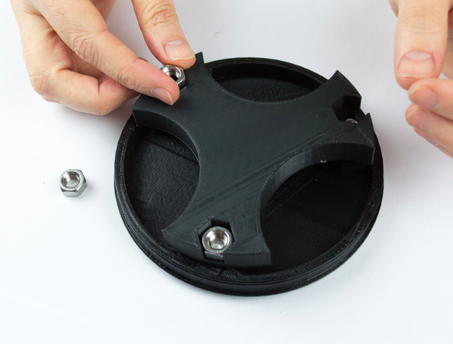
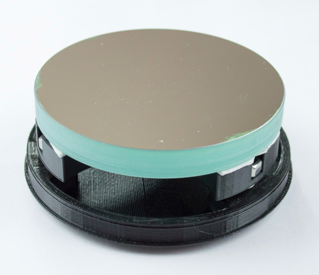
The Mirror Mount and the Mirror Base are first connected together by placing three 8mm nuts through the Mirror Base. The three springs are then threaded onto the shaft of the bolts before the Mirror Mount is placed on the bolts and fastened by three 8mm nuts that are captured by hexagonal holes in the Mirror Mount. The Mirror Mount should be placed so that the hexagonal holes are facing away from the Mirror Base with the nuts visible after assembly.
Étape 3 - Attach the Mirror to the Mirror Mount.
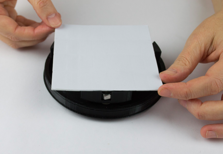
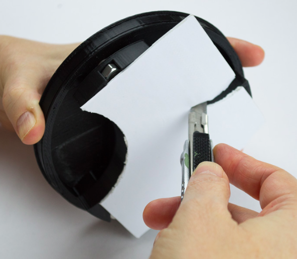
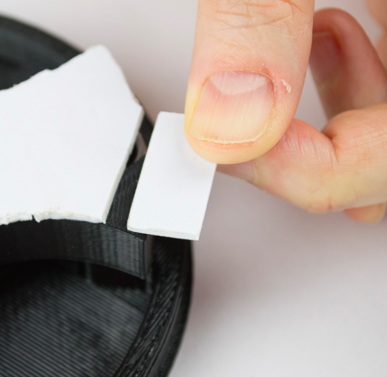
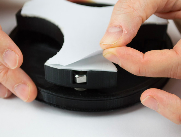
The double-sided tape pad may then be stuck to the surface of the Mirror Mount and trimmed to size with a sharp knife.
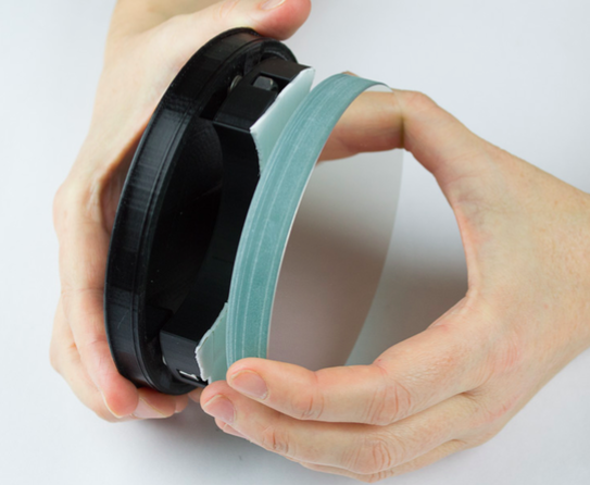
Finally the Mirror is attached to the other side of the double-sided tape, taking care to get it central and aligned with the circumference of the Mirror Mount.
The Mirror alignment may then be adjusted by rotating the 3 bolts. Ensure that the gap between the Mirror Base and the Mirror Mount is the same near all three bolts. This can be done by using a drill bit as a guage.
Étape 4 - Pi Camera mounting
The Spider Assembly provides support for the Pi camera on the axis of the telescope and a method of moving the camera backwards and forwards along the telescope axis to allow focusing.
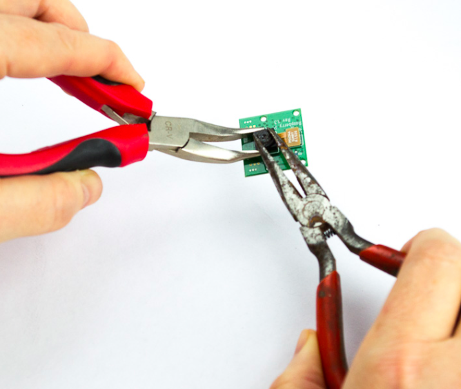
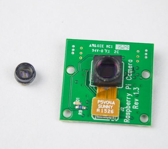
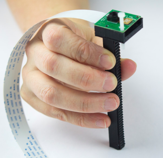
The Pi Camera is mounted on the camera mount which already has a rubber gear rack attached. The first step is to prepare the Pi camera by removing the camera lens to expose the sensor. The lens unscrews from the camera body, but is set in place by a “Loctite” type sealant. Some force may be needed to initially break the seal to unscrew the lens. It is advised that the camera body be held as shown during this step. After separation the lens may be discarded.
Print your own builders please note: The Camera Mount requires a T 2.5 Timing belt which is adhered to the shaft with super glue. The belt is supplied with the print your own kit.
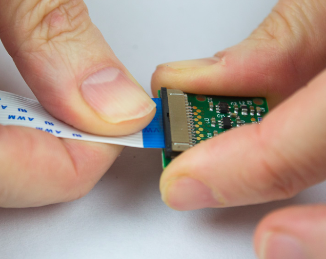
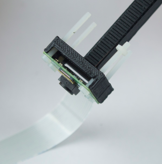
The ribbon cable, which connects the Pi Camera to the Raspberry Pi computer, is then inserted into the Pi Camera. The Pi Camera is then attached to the Camera Mount by 4 x 2mm nuts and bolts.
Étape 5 -
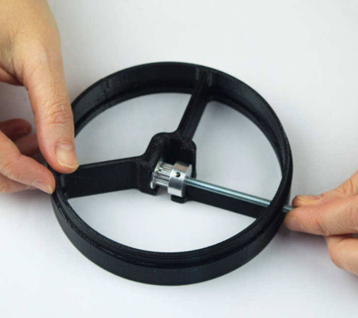
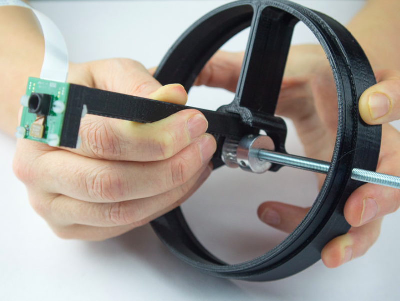
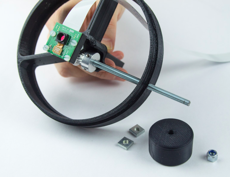
The focus mechanism is assembled next. This consists of a cog connected to a screw threaded shaft and a Focus Knob attached to the threaded shaft by two locking square nuts and a lock nut.
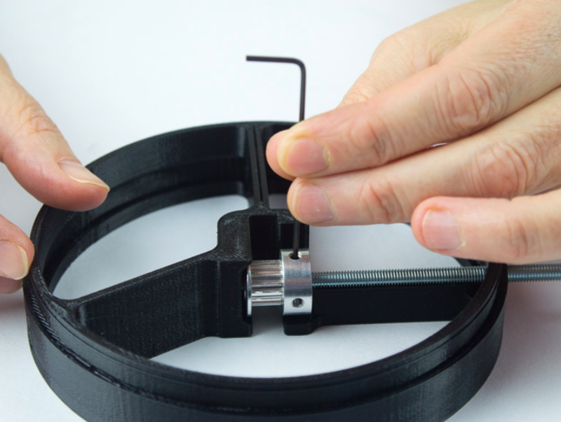
The cog is placed in the centre of the Spider as shown. The Threaded Shaft is then fed through a hole in the Spider circumference into the centre of the cog and locked in place with a hex grub screw. The Camera Mount assembly is then fed through the gap between the cog and the spider plastic. This may be stiff at first, but will ease by after a few passes. It is important that there is a tight fit for smooth focusing.
Étape 6 - Focus Knob
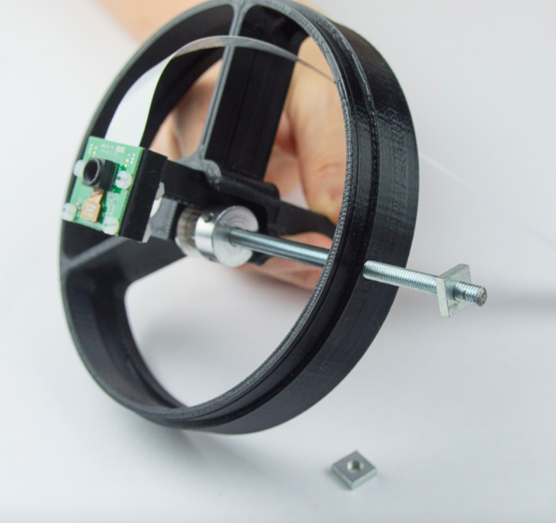
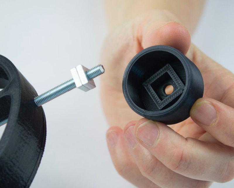
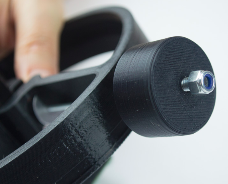
The focus knob is attached by placing the square recess in the knob over two locking square nuts and holding it in place with a lock nut. Position the first nut on the treaded shaft and turn, checking with the depth of the Focus Knob so that there is enough length of shaft above the first nut to place the Focus Knob and lock nut. Then attach the second square nut and lock the two nuts together. Place the Focus Knob over the Threaded Shaft and engage the square recess in the Focus Knob.
Étape 8 - Raspberry Pi case
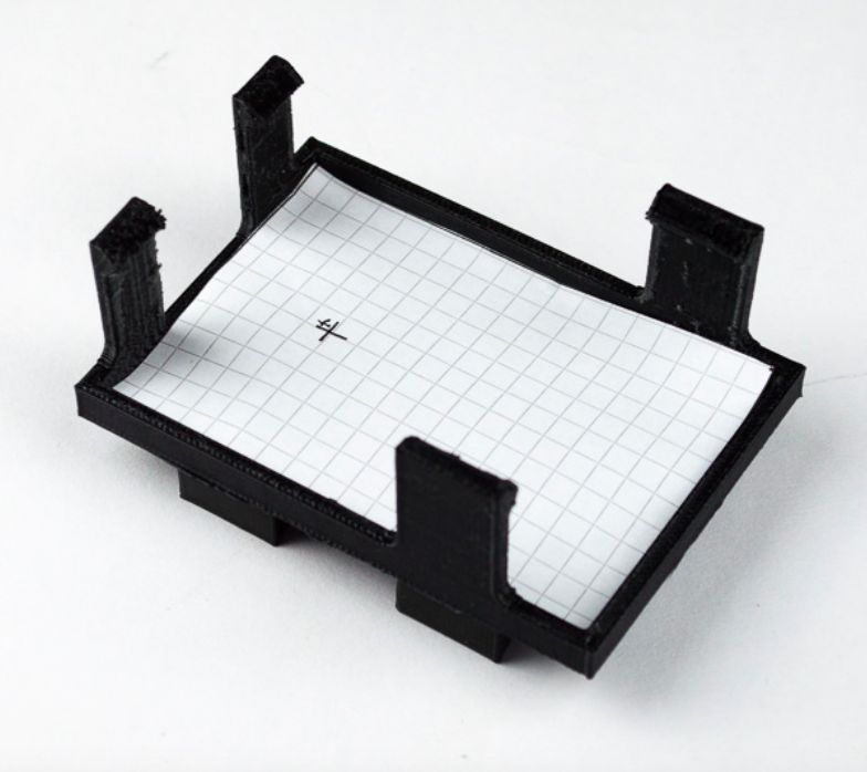
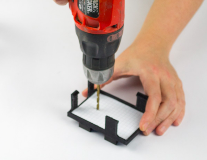
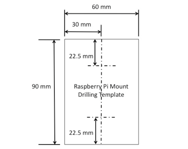
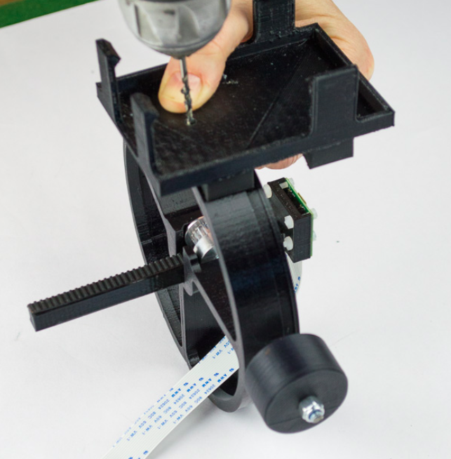
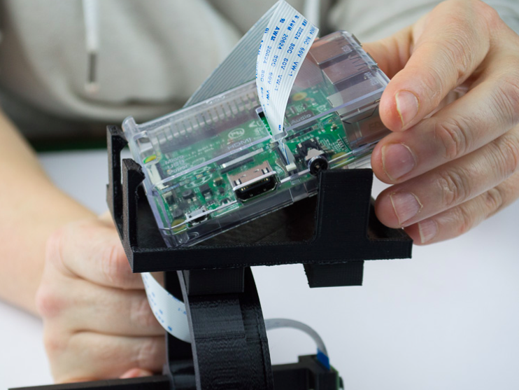
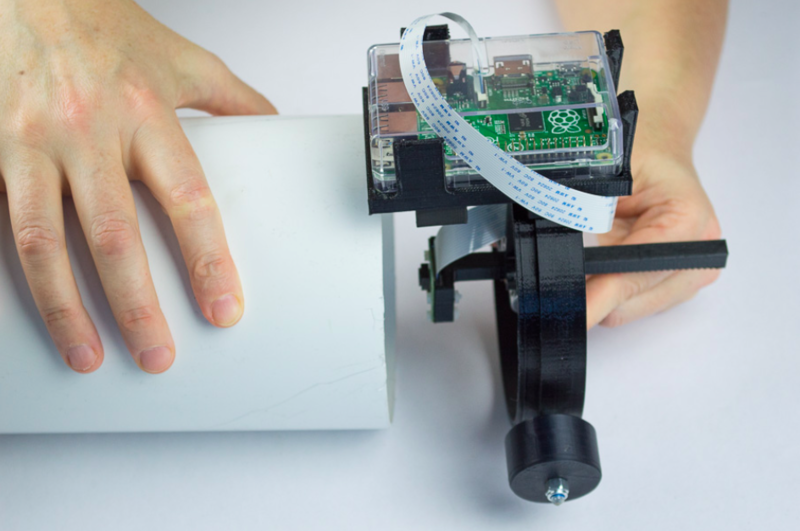
The Raspberry Pi case will be attached to the Spider by the Raspberry Pi mount and a single self-tapping screw. A hole should be drilled through the Raspberry Pi mount (4mm) to clear the self-tapping screw. On kits with printed parts supplied there is a mark (solder iron dab) at the correct position. For those printing their own plastic, template dimensions are below.
Étape 9 - Self-tapping screw will tap
A 2.5 mm is made in the Spider circumference the 3.5mm self-tapping screw will tap. The hole is made over one of the legs of the spider so that the self- tapping screw does not protrude.
Étape 10 - Notes for builders printing their own 3D printed components.
The Raspberry Pi mount is printed in 3 parts and glued together with super glue:
- 1 off – Raspberry Pi Mount.STL
- 2 off – Rasp Pi Mount Part 2.STL
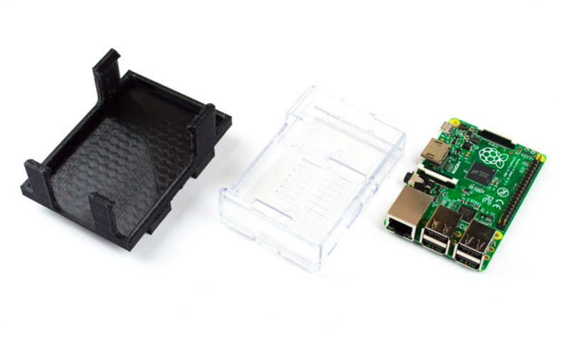
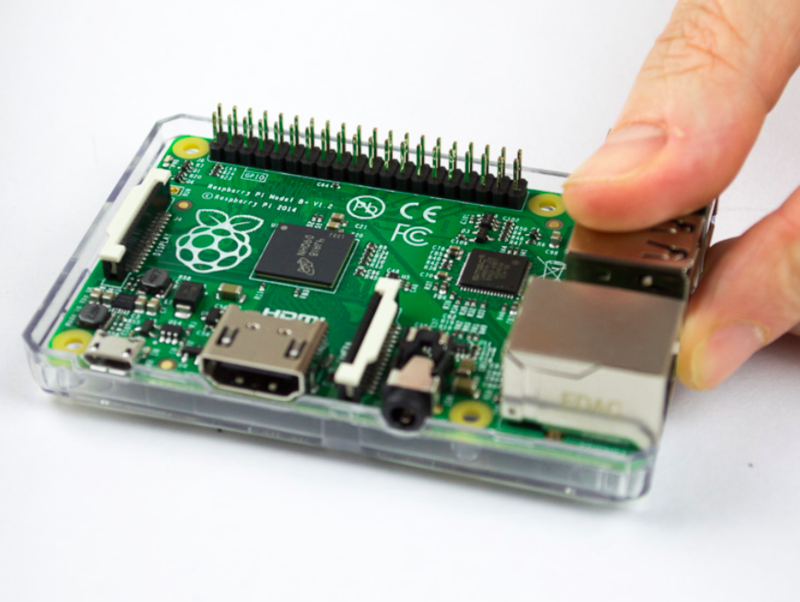
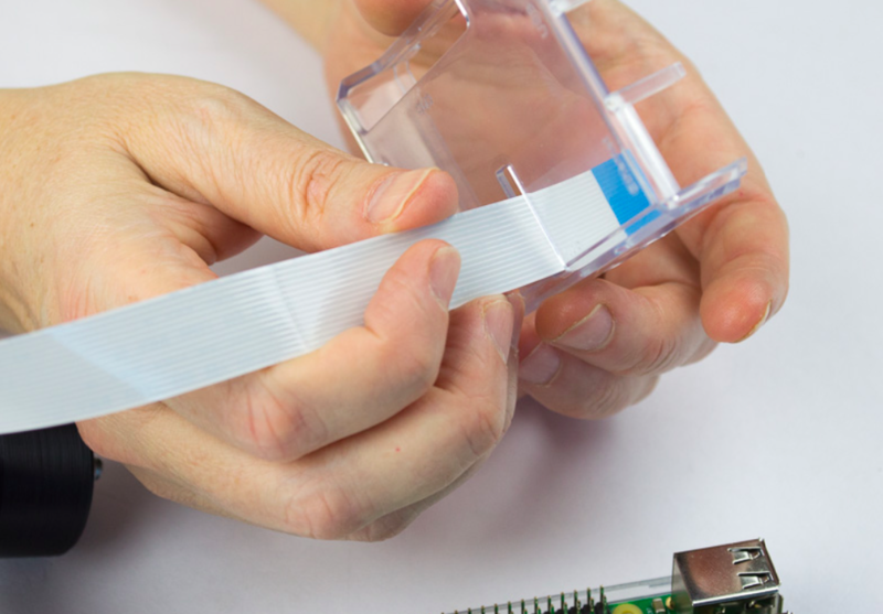
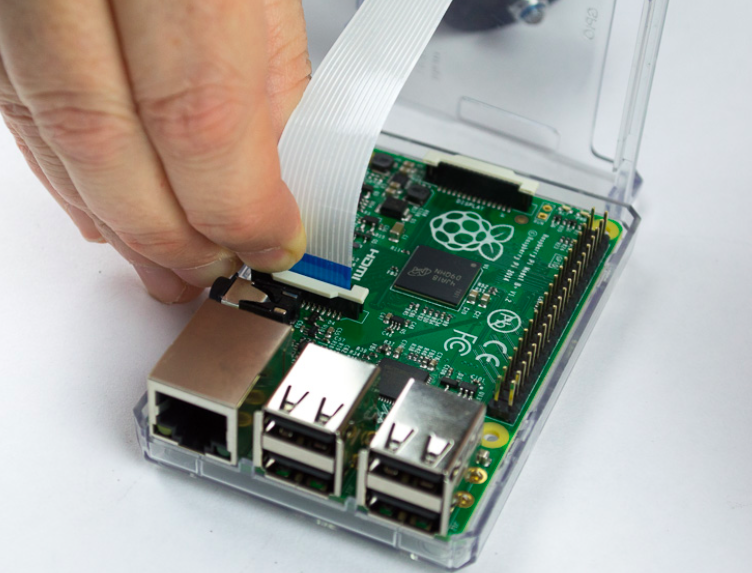
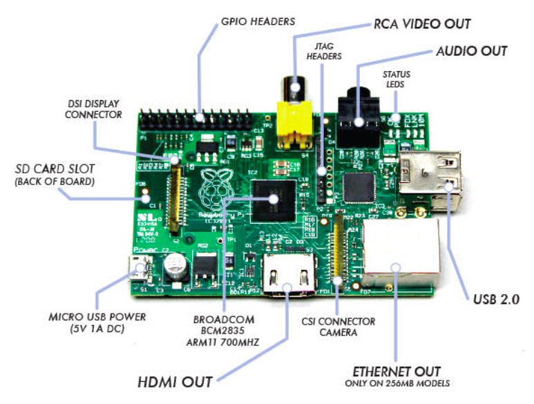
The Raspberry Pi case is transparent and in two parts. The camera ribbon cable is threaded through the lid before being inserted into the CSI Camera connector on the Raspberry Pi board. The two parts then clip together and finally insert into the Raspberry Pi Mount.
Étape 11 - General assembly and Tripod Mount
Before assembling the telescope, you may wish to improve its performance by painting the inside of the Tube with matt black paint.
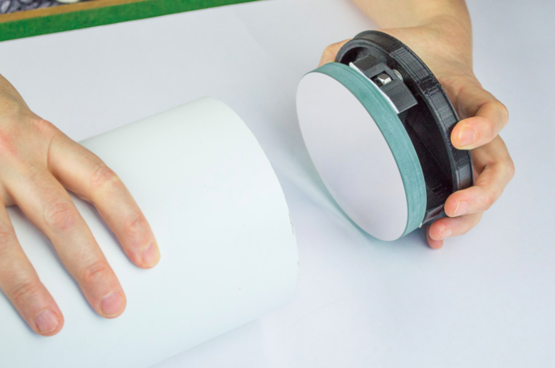
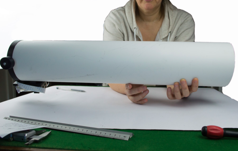
The tripod mount is located at the centre of gravity of the tube. This is determined by pressing the Spider and Mirror assemblies into position on the tube. It is recommended that they be held in place with Gafa (Duct) tape while doing the next stage.
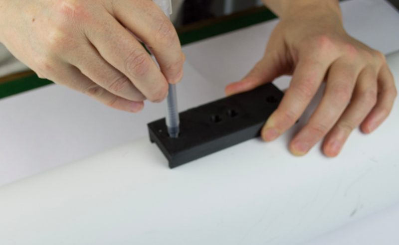
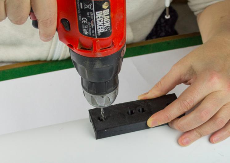
Then balance the telescope on an object or your hand to determine the centre of gravity. Mark this on the tube and then use the Tripod Mount to mark the position of two drill holes needed to fix the tripod mount.Remove the Mirror and Spider assemblies before drilling out the two holes with sufficient clearance for the two nuts provided. Then attach the Tripod Mount with the two nuts and bolts.
You may now replace the Mirror and Spider assemblies.
The spider and Mirror Base are permanently held in place with the 3.5mm self-tapping screws provided. A 2.5mm drill is provided to drill trough the tube into the side of the Spider and Mirror Base. It is recommended that initially the spider should be secures by Gaffa tape and the orientation of the camera set on the first trial before drilling the tube.
Étape 12 - Notes Instructions and STL Files only customers
The mirror used in the kit is a 41⁄2 inch, 113 mm spherical, focal length 600mm. The length of the Telescope Tube is 610mm. That is the telescope tube is just 1 cm longer than the focal length of the mirror. To determine the focal length of a third party mirrors, simply image a distant object onto a piece of paper and measure the distance between the mirror and the paper. The PiKon is designed with a long travel on the focusing rack and is forgiving of small inaccuracies in focal length measurement. Measure twice, cut once!
Étape 13 - Setting up the Raspberry Pi
The Raspberry Pi will require a power supply, USB keyboard, HDMI display and Mouse for graphic user interface (GUI). A VGA monitor may be used with a HDMI to VGA adaptor.
The Raspberry Pi is supplied with a pre-programmed micro-SD card. On power up the on screen instructions will take the user through the stages needed to set up the Raspberry Pi.
It is recommended that the Raspian operating system be installed. The PiKon image capture is performed using command lines, so it is more convenient to select boot up to command line during set up, than boot up to GUI. On first use of the camera you may see an error message requesting that the camera be enabled in settings. Simply follow the instructions.
Étape 14 - Command Line Syntax
A full set of Raspberry Pi Camera commands can be found here.
For image capture use:
Raspistill –o test.jpeg –t 30000 –hf
“Raspistill –o test.jpeg” .... Takes an image in jpeg file format called “test” with a short default on screen preview.
–t 30000 .... Sets the on screen preview time before the image is taken. Units are in milliseconds, therefore this command would use a 30 second preview.
-hf ...... flips the image horizontally. The image at the camera sensor is a mirror image.
Étape 15 - Setting up
Because the PiKon does not have an eye piece, setting up the telescope is done on screen.
Initially, use a “Raspistill –o test.jpeg” command, just to make sure everything is working and that the camera is correctly attached. Next, focus the telescope on a distant object. Extending the time (-t) command can give useful extended preview time:
Raspistill –o test.jpeg –t 120000 –hf
Once focus point is established, remove the Gaffa tape from the Spider and rotate the Spider in the Telescope Tube until the image is upright. If satisfied, the Spider can then be fixed with the self-tapping screws. And now you are ready for the night sky. It is suggested that your first object should be the moon. This will help familiarize you with the operation of the PiKon.
Your images can be viewed on the Raspberry Pi. I have found that the most convenient way to transfer images to an external computer is to use Dropbox from the Raspberry Pi.
Good luck and please share your experiences, images and any software that you may wish to create!
Notes et références
- Mirrors and parts can be obtained from our shop: http://www.pikon.online
Published
 Français
 English
 Deutsch
 Español
 Italiano
 Português