(Mise à jour pour être en accord avec la nouvelle version de la source de la page) |
(Mise à jour pour être en accord avec la nouvelle version de la source de la page) |
||
| Ligne 314 : | Ligne 314 : | ||
"Bentolux" project - main box design - to be available soon on WikiFab (around July 2018). | "Bentolux" project - main box design - to be available soon on WikiFab (around July 2018). | ||
| − | French page | + | French page describing this project can be found here: https://wikifab.org/wiki/MoodBox |
}} | }} | ||
{{ {{tntn|Tuto Status}} | {{ {{tntn|Tuto Status}} | ||
|Complete=Published | |Complete=Published | ||
}} | }} | ||
Version du 14 juillet 2018 à 21:58
Sommaire
- 1 Introduction
- 2 Video d'introduction
- 3 Étape 1 - 2D design (new tier for the box)
- 4 Étape 2 - 3D design
- 5 Étape 3 - Laser engraving ad cutting of the new box tier
- 6 Étape 4 - 3D-printing
- 7 Étape 5 - Wiring diagram
- 8 Étape 6 - Arduino programming
- 9 Étape 7 - Assembling, testing and finishing off
- 10 Étape 8 - Now let's dance!
- 11 Notes et références
- 12 Commentaires
Introduction
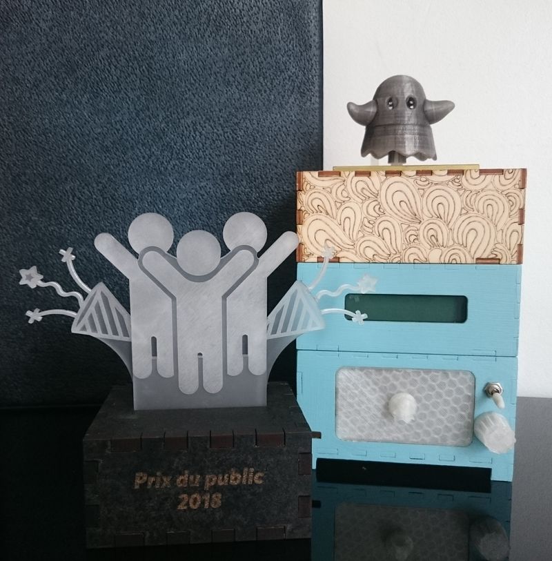
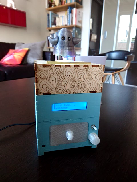
This modular box is a 3-tier set. Once on, it provides basic weather station information (temperature, humidity, atmospheric pressure) but becomes a "Mood box", here a jukebox actually, when properly activated.
Preamble
This project is a group project (FaB team) carried out during a French hybrid training program called "Fabrication numérique" (CNC machining and fabrication) - class of 2018, July.
This final group project involves some of the know-how acquired during the training program and seals the deal. It is complementary with the "Bentolux" project which should be documented and referenced soon on wikifab.org.
Instructions for the project were:
- create a new tier to the box designed and developed during the course of the training program (3 available tiers: 1 base, 1 in Plexiglas, 1 for LCD screen);
- use newly acquired knowledge for this new tier: 3D printing, laser cutting, etc.;
- program with Arduino at least one user interaction (free choice).
Overall specifications
After some thought our group decided to create a musical tier - we called it "Mood box" - to complement the weather station using the base-tier and the LCD-tier.
Expected behavior is described here below.
Starting the box
When properly plugged in, the box can be started by using the switch on the front.
Starting the box triggers the following events:
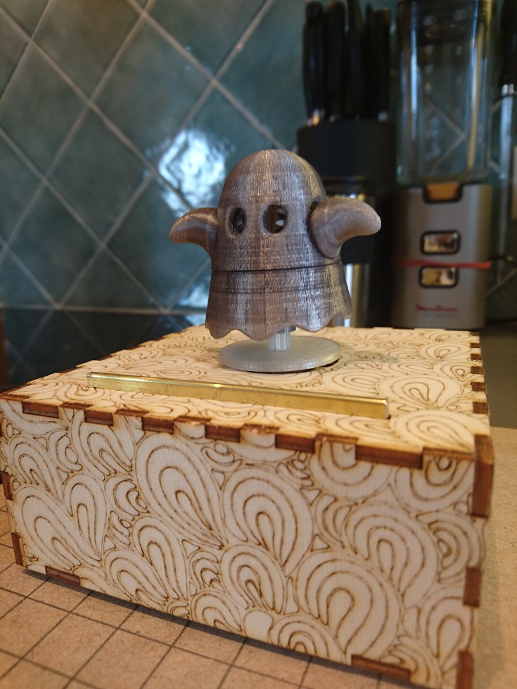
- figurine set on top spins on its stand;
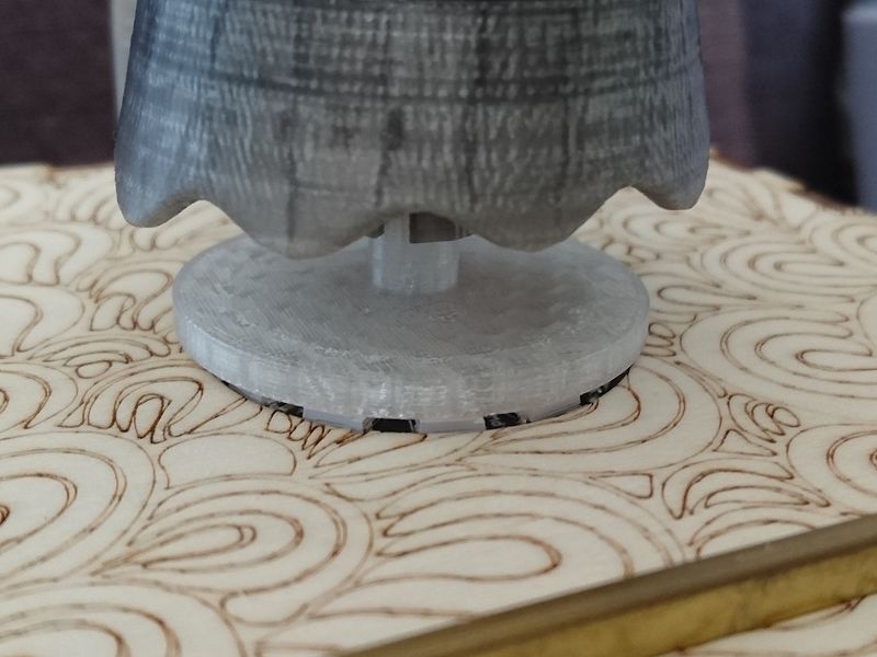
- LED-ring light effect shows through the figurine's translucent stand;
- LCD screen displays a welcome message.
If no other action is made right away, the box goes in "sleep mode".
In "sleep mode", temperature and humidity are displayed with a custom message on LCD screen.
These custom messages as well as the color set for both the LED-ring and LCD screen depend on current temperature:
- LCD and LED-ring color varies from blue to red when temperature rises;
- LED-ring sparkles at a random frequency to add some animation;
- custom message is displayed on LCD screen according to the temperature range currently reading.
Mood box activation and functionalities
Mood box is activated when the user touches the brass bar placed on top of it - this bar is connected to a capacitive sensor set inside the box.
Upon activation, figurine, LED-ring and LCD wake up.
Cette activation est accompagnée d'une animation conjointe de la figurine, de l'anneau de LEDs et de l'écran LCD.A new tap triggers play mode.
First time, playlist begins with the first title on the list.
The potentiometer button - placed under the on/off switch on the front - is then active and serves as volume control for music.
The brass bar remains also active and stands by pending new user interaction.
While music plays, action differs depending on how many times the bar is touched:
- 1 tap: "pause/play", i.e. the music is paused if playing before or begins playing if paused before and LCD displays a message accordingly;
- 2 taps:"next", i.e. the player jumps to the next title on the list;
- 3 taps:"previous", i.e. the player changes the current title for the previous one;
- 4 taps or more: "stop", i.e. the box returns to sleep mode after a short animation of figurine, LED-ring and LCD screen.
During play time, LED-ring lights up in a rainbow sequence and figurine spins on top of its stand.
Note: Each time a play/pause/next/previous action is taken into account, figurine spins in other direction.
Deactivating the Mood box
After activating the Mood box or when the music is stopped, if the bar remains idle for more than 5 seconds, sleep mode kicks in and deactivation occurs.
Note: When exiting sleep mode and resuming playing music, the player starts from where it was when deactivated.
Matériaux
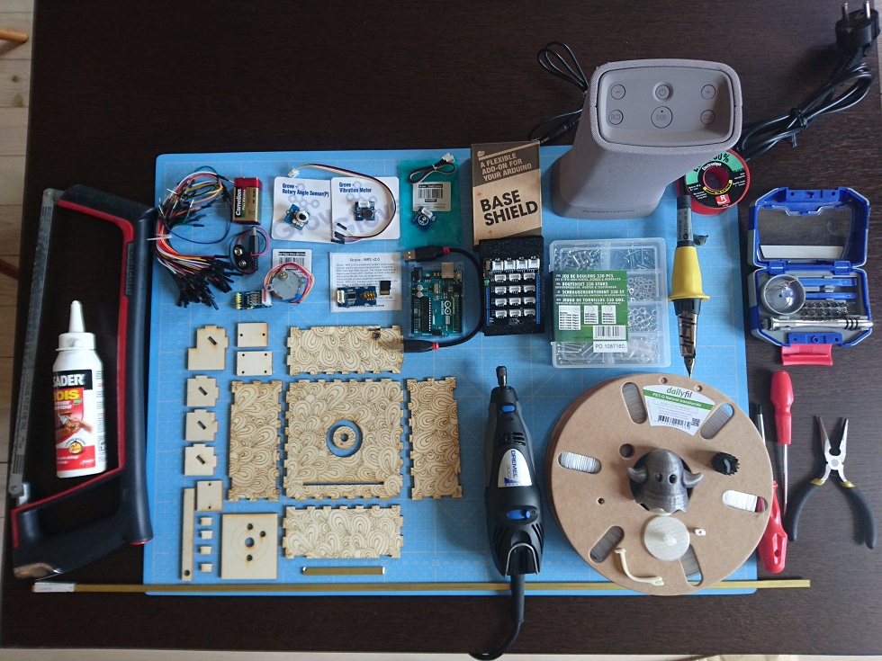
Necessary materials are listed here below by category.
For the box
- poplar plywood 3mm-thick for laser cutting
- brass bar 80x7x2mm - to change and increase the touching area with regards to the capacitive sensor
- transparent PLA for 3D printing:
- access door to base tier
- figurine's stand and support - the stand will also diffuse the LED-ring light
- button for volume control
- lateral joints
- colored PLA (according to maker's preference) for the figurine and/or scenery set on top of the box
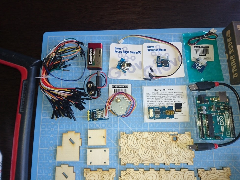
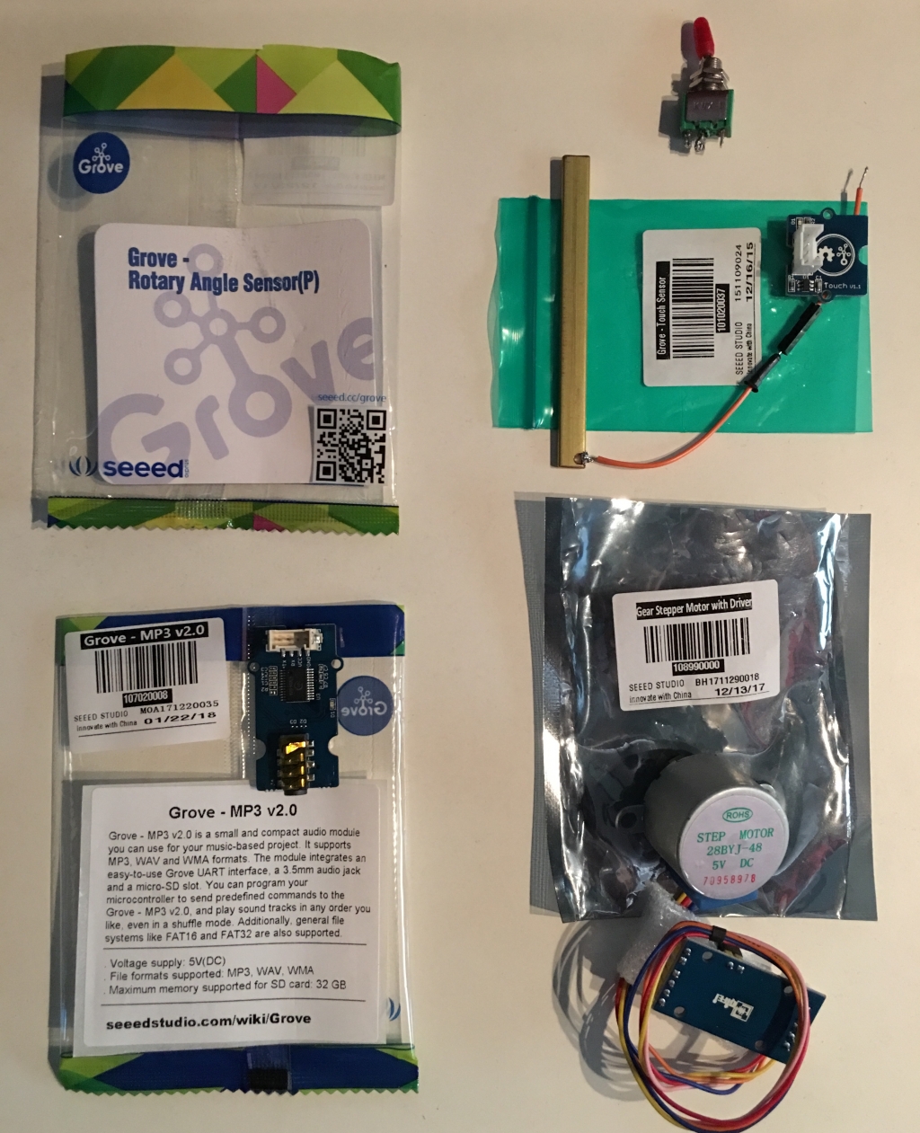
Electronic supplies
- 1 Arduino Uno Rev.3
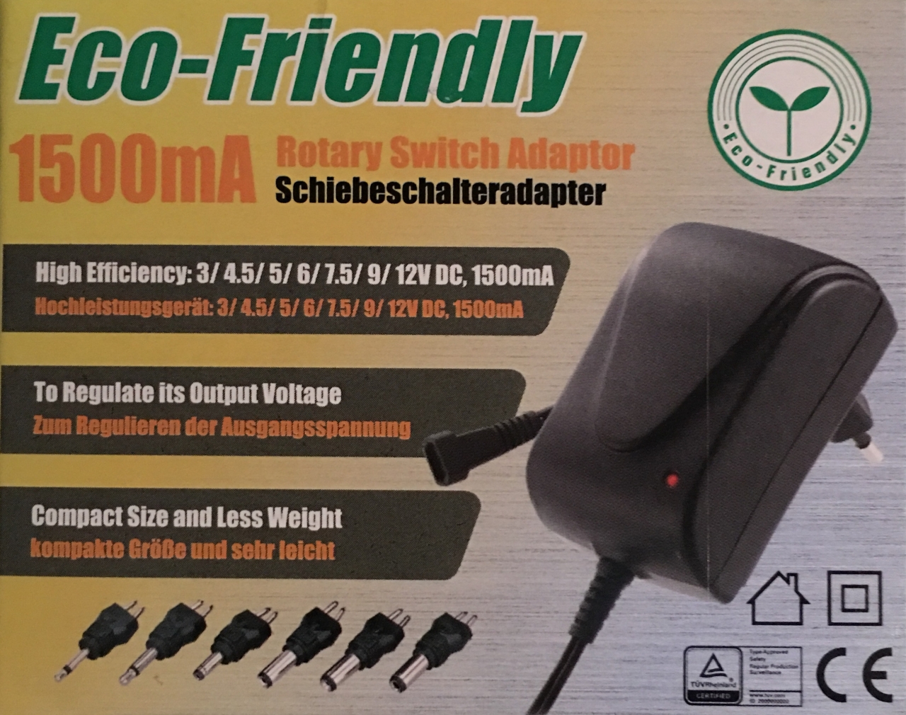
- 1 MW power supply: 1500mA Rotary Switch Adaptor
- 1 reversing switch KNX-1, 3A, 250V AC, to be used as main switch
- 1 Seeed Studio potentiometer: Grove Rotary Angle Sensor (P)
- 1 Seeed Studio capacitive sensor: Grove Touch Sensor
- 1 Adafruit LED-ring: Neopixel Ring 12 x 5050 RGB
- 1 Seeed Studio MP3-player: Grove MP3 v2.0
- 1 micro SD-Card to store the playlist
- 1 Seeed Studio Gear Stepper Motor with Driver: Step Motor 28BYJ-48 5V DC
- 1 Adafruit BME280 sensor: temperature, humidity, pressure (ADA2652)
- 1 Seeed Studio "Base Shield V2"
Misc.
- wood glue, to assemble and joint laser cut parts of the box tiers
- cyanoacrylate glue
- some screws to fasten sensors and other components inside the box tiers
- cables and jumper wires
Outils
Tools used during this project are hereby grouped by use.
CAD & programming
- Inkscape, 2D CAD software to create and adapt cutting and engraving patterns for the box
- TinkerCAD, Blender or any 3D CAD software to create or modify figurine and other box printable components
- Arduino IDE, programming environment adapted to Arduino and used to create and transfer the code managing all interactions between sensors and the outside world
Machines & tools
- laser cutter, usually available in FabLabs
- 3D printer, also available in FabLabs
- soldering iron and materials
- screwdriver, wire cutters, saw, etc.
- Dremel-like tool
Étape 1 - 2D design (new tier for the box)
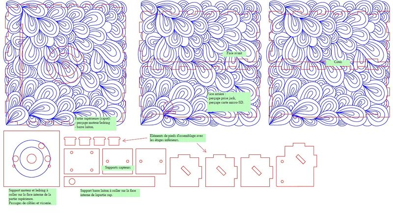
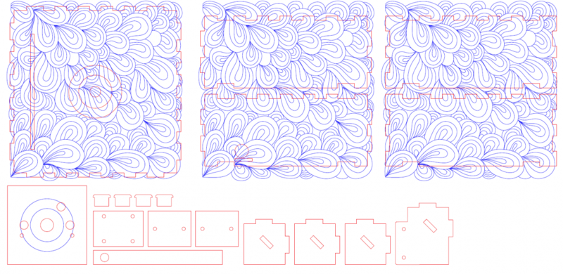
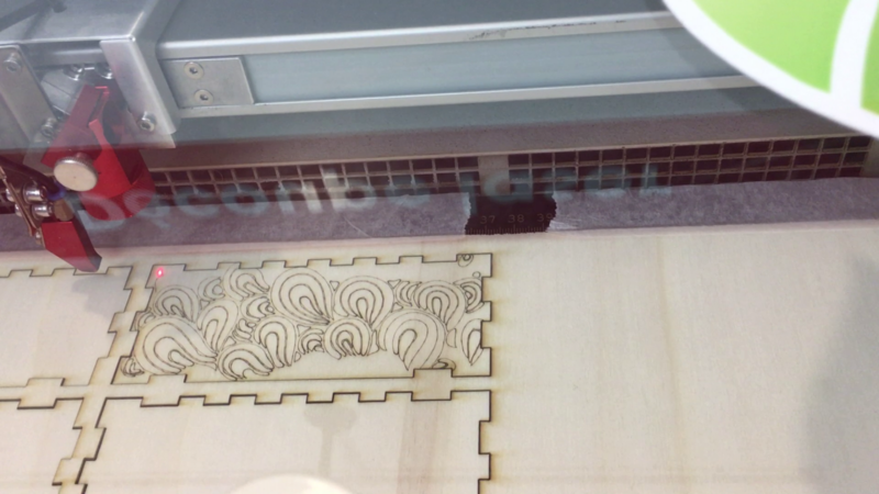
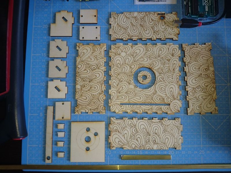
Goal was to create a new tier to the original box by using laser cutting of course but also laser engraving.
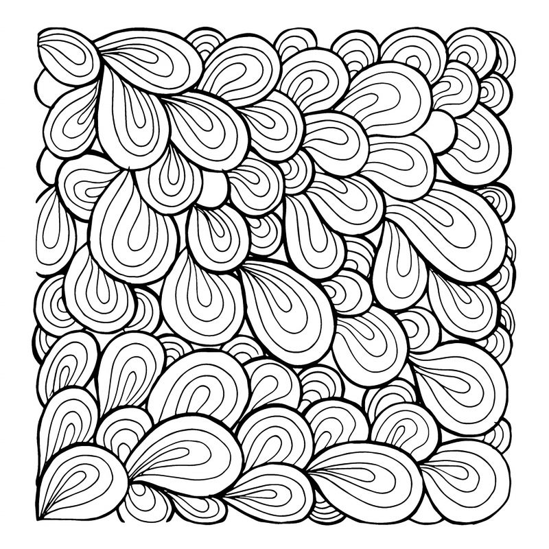
An engraving pattern was found.
This image file was reproduced using Inkscape and Beziers curves.
This newly designed pattern was then added to the cutting pattern.
Étape 2 - 3D design
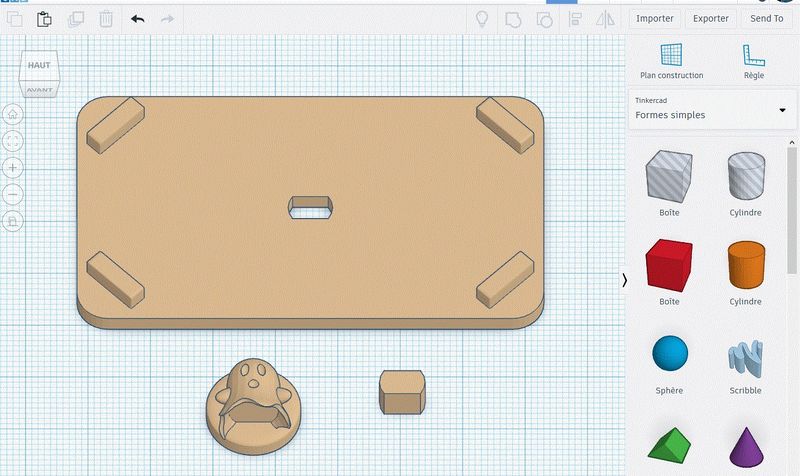
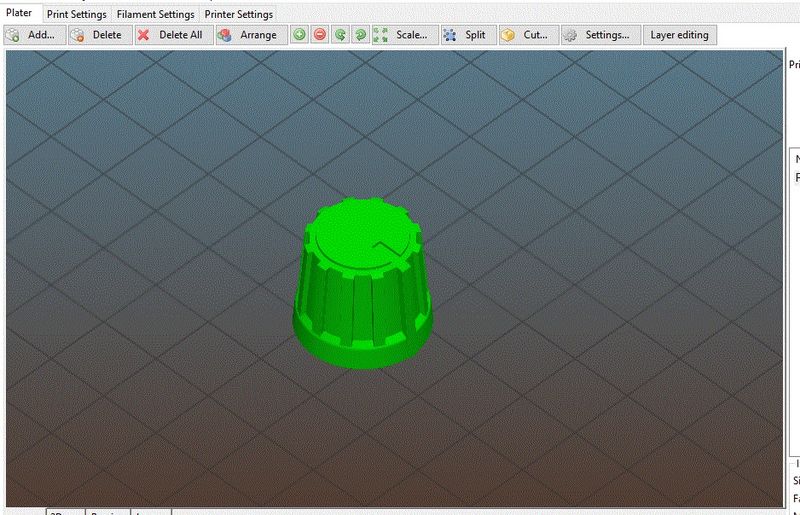
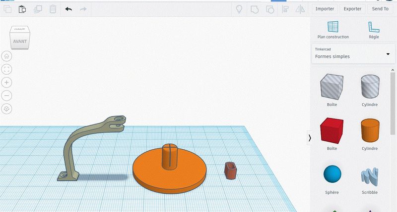
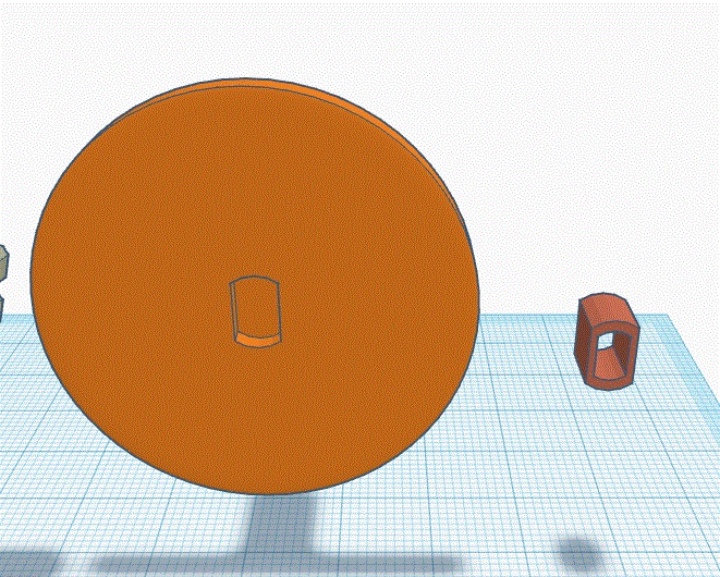
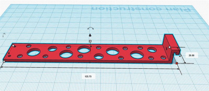
The components to be 3D-printed are the following:
- access door for the base tier alongside with the main switch and potentiometer
- button to cover the potentiometer toothed wheel
- figurine stand which also serve to subdue LED-ring lighting effects
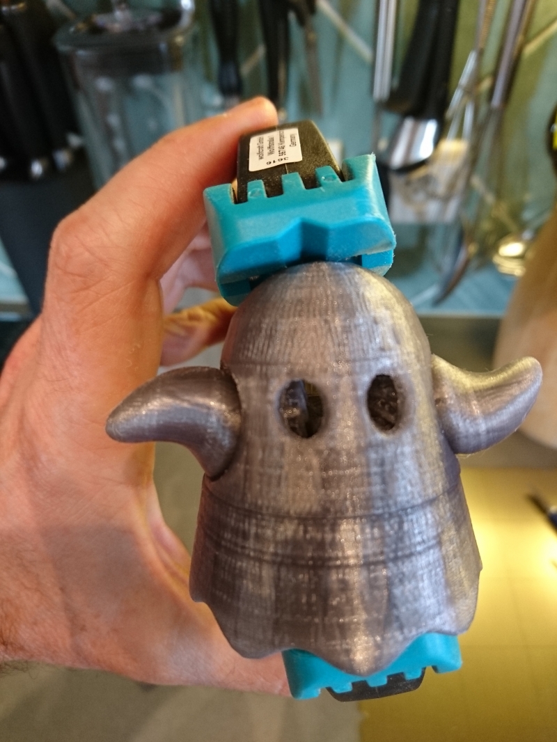
- figurine itself, in this instance the "Funkgeist" animated ghost found on Thingiverse (https://www.thingiverse.com/thing:570654) and its support elements
- lateral joints to ensure the box solidity
For this step, Inkscape, TinkerCAD and Blender were used.
Étape 3 - Laser engraving ad cutting of the new box tier
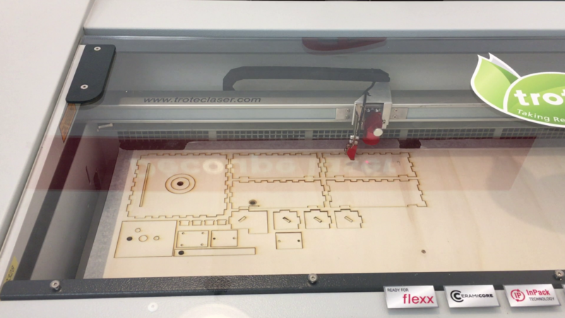
Laser cutting - and engraving - has been carried out within the EdFab in Saint-Denis, France, under the kindly direction of Lola and Arthur: big thanks to both of them!
2 other identical tiers have been made using SqyLab facility in La Verrière, France, with the benevolent help of Francis in discovering yet a new source file pre-processing due to a different machine. An equal big thanks to him!
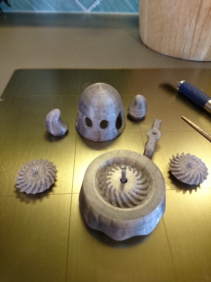
Étape 4 - 3D-printing
All printings needed for the project were made on a Prusa i3 MK3.
Those are shown as opposite:
- base tier
- access door
- button to put on the potentiometer toothed wheel
- MoodBox tier
- figurine stand (spinning) and support (fixed)
- figurine itself
- lateral joints
Étape 5 - Wiring diagram
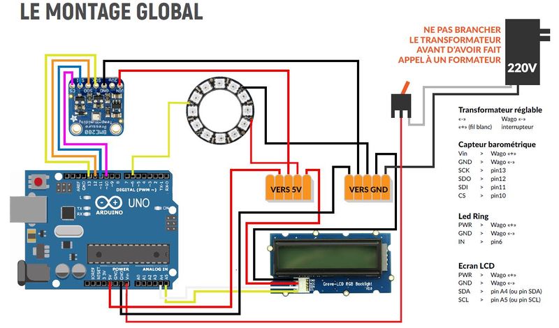
Sensors and other elements are connected to the base-shield set on top of the Arduino Uno as described here after with port numbers.
Input
- Potentiometer: analog input A0
- Capacitive sensor: analog input A1
- BME280 sensor:
- Vin: 5V
- GND: GND
- CS: 10
- SDI: 11
- SDO: 12
- SCK: 13
Output
- LCD: I2C port
- MP3 player: D2
- LED-ring: D3
Motor
- Step motor
- IN 1: 10
- IN 2: 9
- IN 3: 11
- IN 4: 8
Power supply
It's important to notice that all in all, components need a lot of power to work properly. There is not enough power available through USB connection (about 5V) and a 9V battery will be depleted faster than you'd like.
This is why we used an adaptor that can be plugged into a wall-socket and deliver enough power steadily.
Étape 6 - Arduino programming
Programming was a bit tricky due to Arduino native sequential working.
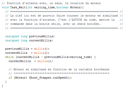
Workarounds must have been found in order to animate several parts of the box not only sequentially but also simultaneously.
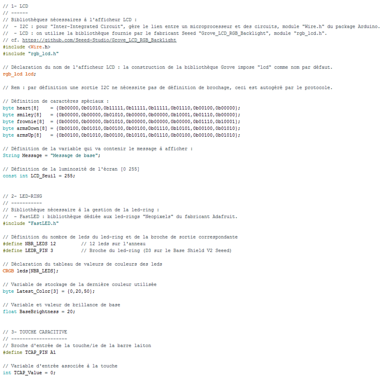
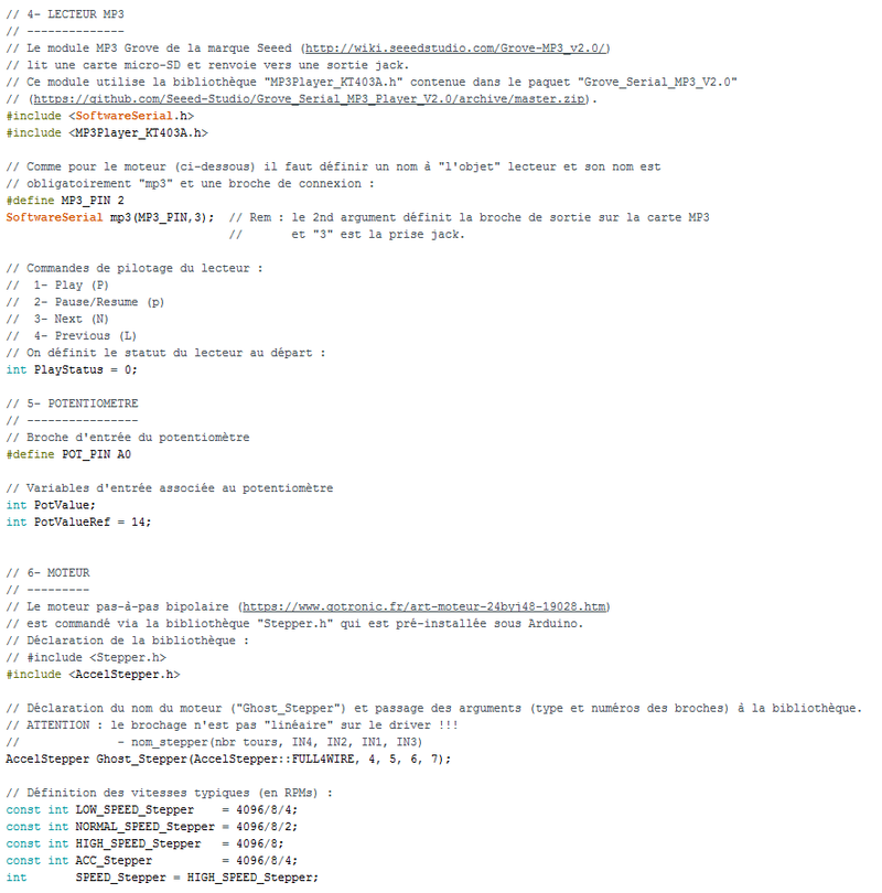
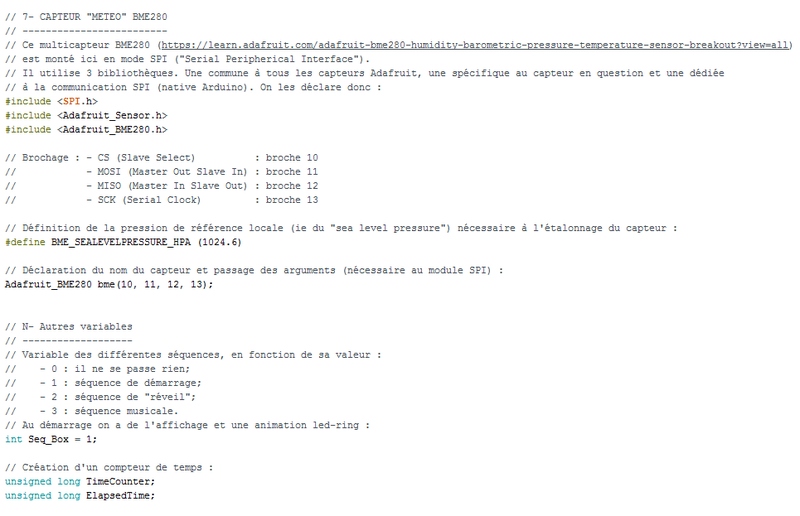
The first 3 screenshots as shown opposite exhibit declarations for each component of the box and the MoodBox tier.
Main program is a loop which executes the sequence as requested with regards to user interaction. Each sequence is identified with a number:
- 0: sequence where nothing happens
- 1: start sequence
- 2: awakening sequence, triggered by at least one touch on the brass bar
- 3: music sequence
Waiting time management, especially for counting how many times the bar was touched, is using the millis() function to avoid using the delay() function where the whole program is put on hold.
To bypass the sequential functioning, the AccelStepper.h library was used as well as combined commands programmed within routines called from the main loop. This allows for example simultaneousness for both LED-ring effects and step motor spinning.
Libraries
Main program calls libraries functions specific to sensors and components used in the box. Those are listed below:
- LCD: "rgb_lcd.h"
- LED-ring: "FastLED.h"
- MP3 player: "SoftwareSerial.h" and "MP3Player_KT403A.h"
- Step motor: "AccelStepper.h"
- BME280 sensor: "SPI.h", "Adafruit_Sensor.h" and "Adafruit_BME280.h
Étape 7 - Assembling, testing and finishing off
Arduino Uno, potentiometer and main switch are connected to the power supply inside and on the base tier of the box (lower tier).
LCD screen is installed in side the LCD tier (middle tier).
MoodBox tier (upper tier) is composed as described here below.
On box walls are fixed:
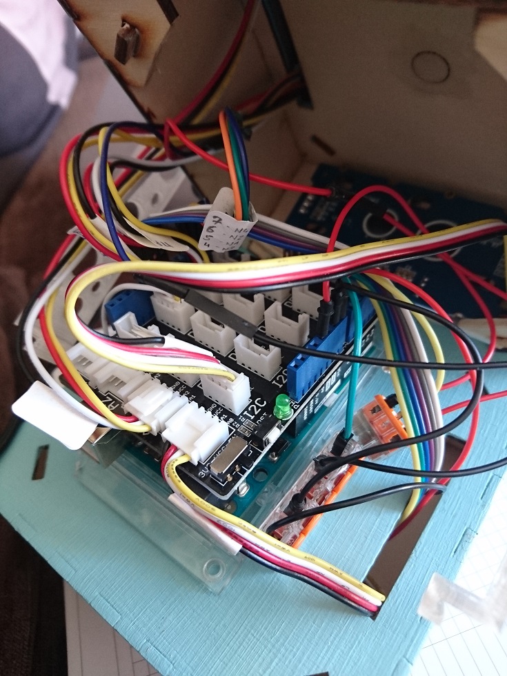
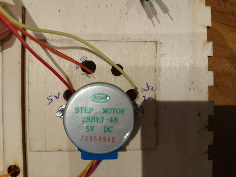
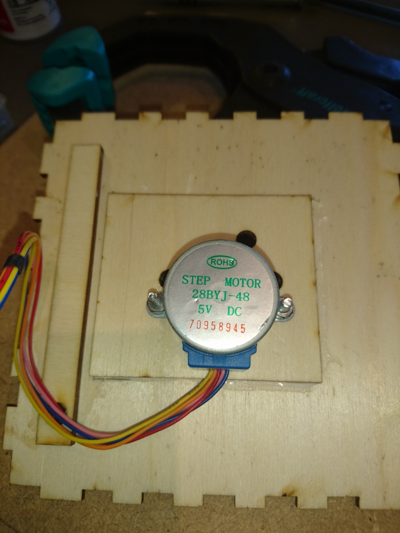
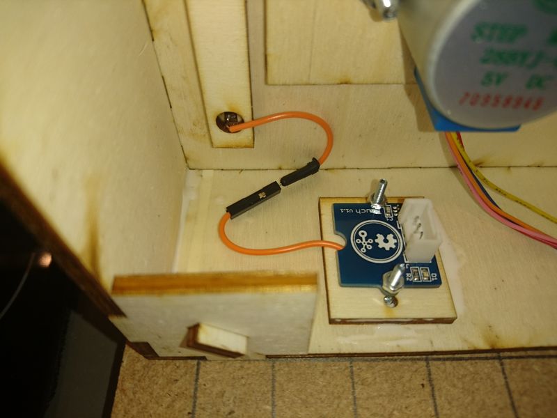
- the step motor used to animate the figurine - its controller card can be seen on the left on the overview picture as shown opposite
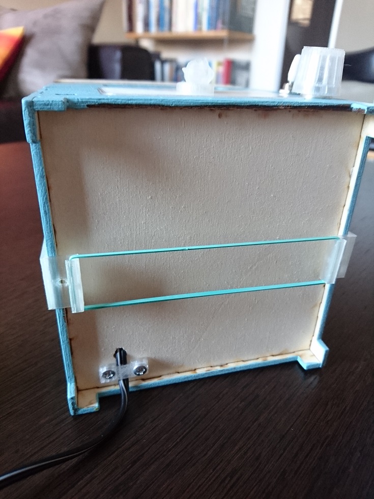
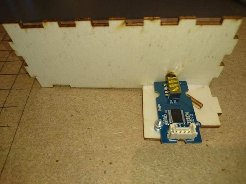
- the MP3 player with both SD-card slot and AudioIn port aligned with MoodBox rear-side wall openings - at bottom on overview picture
- the capacitive sensor to be connected to the brass bar - see the orange wire on the right on the overview picture
Right underneath and throughout the MoodBox top cover are fixed:
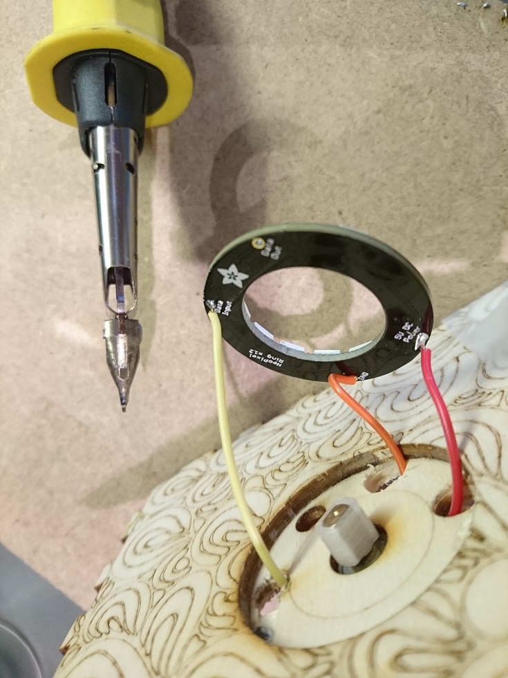
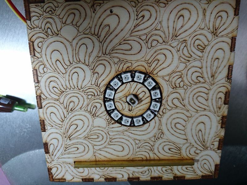
- the LED-ring
- the step motor with only its axis pulling through, centered with the LED-ring
- the brass bar
On top of the MoodBox tier are fixed:
- the figurine stand, just above the LED-ring in order to subdue its bright light
- the figurine itself, set on the motor axis to be able to spin with it
Étape 8 - Now let's dance!
MoodBox tier is now up and able to run.
Please refer to Introduction and overall specifications to properly use it!
Thank you for your interest :)
Notes et références
Figurine used for final presentation comes from Thingiverse (https://www.thingiverse.com/thing:570654).
It was chosen by default. First idea was to recreate in 3D the fabulous Fantasia dancing couple: Hyacinth and Ben Ali Gator.
"Bentolux" project - main box design - to be available soon on WikiFab (around July 2018).
French page describing this project can be found here: https://wikifab.org/wiki/MoodBox
Published




 Français
 English
 Deutsch
 Español
 Italiano
 Português