(Imported page from en.wikifab.org) |
(convert properties for internationnalized Wikifab) |
||
| Ligne 1 : | Ligne 1 : | ||
| − | {{Tuto Details | + | {{ {{tntn|Tuto Details}} |
|SourceLanguage=en | |SourceLanguage=en | ||
|Language=en | |Language=en | ||
| Ligne 5 : | Ligne 5 : | ||
|Type=Creation | |Type=Creation | ||
|Area=Energy | |Area=Energy | ||
| − | |Description=This is the fifth tutorial for building the Pop-up Solar Generator: SunZilla 3.0. Here we are going to assemble the solar panels frames | + | |Description=<translate>This is the fifth tutorial for building the Pop-up Solar Generator: SunZilla 3.0. Here we are going to assemble the solar panels frames</translate> |
|Difficulty=Medium | |Difficulty=Medium | ||
|Cost=200 | |Cost=200 | ||
| Ligne 14 : | Ligne 14 : | ||
|Main_Picture=SunZilla_Step_13_11.jpg | |Main_Picture=SunZilla_Step_13_11.jpg | ||
}} | }} | ||
| − | {{Introduction}} | + | {{ {{tntn|Introduction}}|}} |
{{Separator}} | {{Separator}} | ||
| − | {{Materials | + | {{ {{tntn|Materials}} |
| − | |Material=* 6 x Hinges, 24mm (l) x 20mm (w) x 1mm (th) | + | |Material=<translate>* 6 x Hinges, 24mm (l) x 20mm (w) x 1mm (th) |
* 4 x L-Aluminium profile, 558mm (l) x 20mm (w) x 2mm (th) | * 4 x L-Aluminium profile, 558mm (l) x 20mm (w) x 2mm (th) | ||
* 4 x Squared aluminium profile (better rectangular profiles with 20mm x 8mm), 150mm (l) x 20mm (w) x 2mm (th) | * 4 x Squared aluminium profile (better rectangular profiles with 20mm x 8mm), 150mm (l) x 20mm (w) x 2mm (th) | ||
| Ligne 36 : | Ligne 36 : | ||
* 1 x Female M4-plug | * 1 x Female M4-plug | ||
* 1 x Male M4-plug | * 1 x Male M4-plug | ||
| − | * 3 x Heat shrink tubes (short), for 4 mm² cables | + | * 3 x Heat shrink tubes (short), for 4 mm² cables</translate> |
|Step_Picture_00=SunZilla_Step_13_01.jpg | |Step_Picture_00=SunZilla_Step_13_01.jpg | ||
|Step_Picture_01=SunZilla_Step_13_02.jpg | |Step_Picture_01=SunZilla_Step_13_02.jpg | ||
| Ligne 45 : | Ligne 45 : | ||
}} | }} | ||
{{Separator}} | {{Separator}} | ||
| − | {{Tuto Step | + | {{ {{tntn|Tuto Step}} |
| − | |Step_Title=Drill the PV-module needs | + | |Step_Title=<translate>Drill the PV-module needs</translate> |
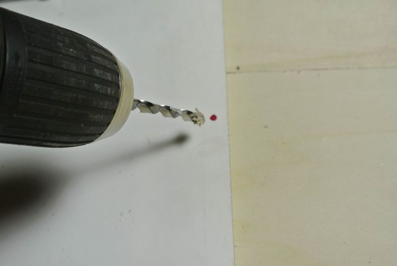
| − | |Step_Content=You can find the positions and diameter of the holes in the .PDF technical drawing which you can download below. For marking those of the PV-modules use a marker pen. For drilling use a metal or wood drill. Two of the 20mm-L-profiles need to have a slot cut along one side; the position of the slots is shown in the .PDF technical drawing downloadable below. These slots will allow the angle of incidence can be adjusted. To slot the profile you should use a milling cutter. | + | |Step_Content=<translate>You can find the positions and diameter of the holes in the .PDF technical drawing which you can download below. For marking those of the PV-modules use a marker pen. For drilling use a metal or wood drill. Two of the 20mm-L-profiles need to have a slot cut along one side; the position of the slots is shown in the .PDF technical drawing downloadable below. These slots will allow the angle of incidence can be adjusted. To slot the profile you should use a milling cutter.</translate> |
|Step_Picture_00=SunZilla_Step_13_05.jpg | |Step_Picture_00=SunZilla_Step_13_05.jpg | ||
|Step_Picture_01=SunZilla_Step_13_04.jpg | |Step_Picture_01=SunZilla_Step_13_04.jpg | ||
| Ligne 55 : | Ligne 55 : | ||
|Step_Picture_05=No-image-yet.jpg | |Step_Picture_05=No-image-yet.jpg | ||
}} | }} | ||
| − | {{Tuto Step | + | {{ {{tntn|Tuto Step}} |
| − | |Step_Title=Connect the profiles on the backside of the modules | + | |Step_Title=<translate>Connect the profiles on the backside of the modules</translate> |
| − | |Step_Content=After drilling, connect the profiles on the backside of the modules with the M5-10mm countersunk bolts, nuts and washers. Take care to place the washer on the side of the nut. | + | |Step_Content=<translate>After drilling, connect the profiles on the backside of the modules with the M5-10mm countersunk bolts, nuts and washers. Take care to place the washer on the side of the nut.</translate> |
|Step_Picture_00=SunZilla_Step_13_06.jpg | |Step_Picture_00=SunZilla_Step_13_06.jpg | ||
|Step_Picture_01=SunZilla_Step_13_07.jpg | |Step_Picture_01=SunZilla_Step_13_07.jpg | ||
| Ligne 65 : | Ligne 65 : | ||
|Step_Picture_05=No-image-yet.jpg | |Step_Picture_05=No-image-yet.jpg | ||
}} | }} | ||
| − | {{Tuto Step | + | {{ {{tntn|Tuto Step}} |
| − | |Step_Content=The frames for the solar modules are made of T- and L-profiles, as shown here: | + | |Step_Content=<translate>The frames for the solar modules are made of T- and L-profiles, as shown here:</translate> |
|Step_Picture_00=SunZilla_Step_13_09.jpg | |Step_Picture_00=SunZilla_Step_13_09.jpg | ||
|Step_Picture_01=No-image-yet.jpg | |Step_Picture_01=No-image-yet.jpg | ||
| Ligne 74 : | Ligne 74 : | ||
|Step_Picture_05=No-image-yet.jpg | |Step_Picture_05=No-image-yet.jpg | ||
}} | }} | ||
| − | {{Tuto Step | + | {{ {{tntn|Tuto Step}} |
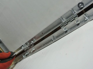
| − | |Step_Content=And they are connected with hinges so they can be unfolded. | + | |Step_Content=<translate>And they are connected with hinges so they can be unfolded.</translate> |
|Step_Picture_00=SunZilla_Step_13_10.jpg | |Step_Picture_00=SunZilla_Step_13_10.jpg | ||
|Step_Picture_01=No-image-yet.jpg | |Step_Picture_01=No-image-yet.jpg | ||
| Ligne 83 : | Ligne 83 : | ||
|Step_Picture_05=No-image-yet.jpg | |Step_Picture_05=No-image-yet.jpg | ||
}} | }} | ||
| − | {{Tuto Step | + | {{ {{tntn|Tuto Step}} |
| − | |Step_Content=When the panel assembly is unfolded, it is held open and flat using the 15 cm long squared aluminium profiles that were cut open on one side. These slide on over the T-profiles from a corner of the unfolded assembly and sit in place halfway up the side of the assembly, as shown. | + | |Step_Content=<translate>When the panel assembly is unfolded, it is held open and flat using the 15 cm long squared aluminium profiles that were cut open on one side. These slide on over the T-profiles from a corner of the unfolded assembly and sit in place halfway up the side of the assembly, as shown.</translate> |
|Step_Picture_00=SunZilla_Step_13_12.jpg | |Step_Picture_00=SunZilla_Step_13_12.jpg | ||
|Step_Picture_01=SunZilla_Step_13_13.jpg | |Step_Picture_01=SunZilla_Step_13_13.jpg | ||
| Ligne 92 : | Ligne 92 : | ||
|Step_Picture_05=No-image-yet.jpg | |Step_Picture_05=No-image-yet.jpg | ||
}} | }} | ||
| − | {{Tuto Step | + | {{ {{tntn|Tuto Step}} |
| − | |Step_Content=The cut square and T-profiles both fit together. | + | |Step_Content=<translate>The cut square and T-profiles both fit together. |
| − | You already drilled fastening holes in the T- and L-Profiles according to the instructions in Step 3 “Preparing the Aluminum Profiles”. The holes to attach the hinges in the L-profiles are different, because they need to be placed according to the hinges you have, and this will vary. To mark the position, place the hinge 5 cm from the end of the profile not on the side of the other holes, like you can see it in the following picture. Then mark the holes with a metal marker. | + | You already drilled fastening holes in the T- and L-Profiles according to the instructions in Step 3 “Preparing the Aluminum Profiles”. The holes to attach the hinges in the L-profiles are different, because they need to be placed according to the hinges you have, and this will vary. To mark the position, place the hinge 5 cm from the end of the profile not on the side of the other holes, like you can see it in the following picture. Then mark the holes with a metal marker.</translate> |
|Step_Picture_00=SunZilla_Step_13_16.jpg | |Step_Picture_00=SunZilla_Step_13_16.jpg | ||
|Step_Picture_01=SunZilla_Step_13_15.jpg | |Step_Picture_01=SunZilla_Step_13_15.jpg | ||
| Ligne 103 : | Ligne 103 : | ||
|Step_Picture_05=No-image-yet.jpg | |Step_Picture_05=No-image-yet.jpg | ||
}} | }} | ||
| − | {{Tuto Step | + | {{ {{tntn|Tuto Step}} |
| − | |Step_Title=Solar Module Cables | + | |Step_Title=<translate>Solar Module Cables</translate> |
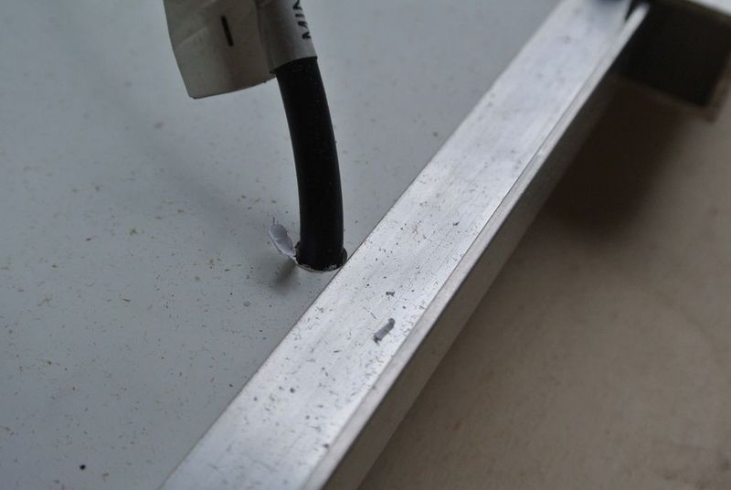
| − | |Step_Content=After the solar modules are connected to the folding mechanism, their cables need to be connected and fixed. The first step is to bring the cables to the backside of the solar panels. Drill holes as you can see near to the connection box of the panels. Afterwards you can push the cables to the other side. | + | |Step_Content=<translate>After the solar modules are connected to the folding mechanism, their cables need to be connected and fixed. The first step is to bring the cables to the backside of the solar panels. Drill holes as you can see near to the connection box of the panels. Afterwards you can push the cables to the other side.</translate> |
|Step_Picture_00=SunZilla_Step_14_01.jpg | |Step_Picture_00=SunZilla_Step_14_01.jpg | ||
|Step_Picture_01=SunZilla_Step_14_05.jpg | |Step_Picture_01=SunZilla_Step_14_05.jpg | ||
| Ligne 113 : | Ligne 113 : | ||
|Step_Picture_05=No-image-yet.jpg | |Step_Picture_05=No-image-yet.jpg | ||
}} | }} | ||
| − | {{Tuto Step | + | {{ {{tntn|Tuto Step}} |
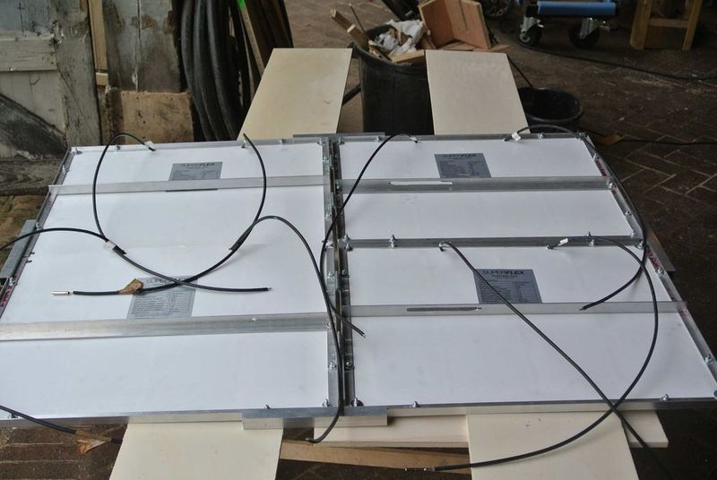
| − | |Step_Content=The cables need to be soldered in series as you can see in attached wiring diagram. So you connect the positive pole of one panel with negative pole of the following. To do so you have to lay the cables in some cases through the profiles in between. So that they are not squeezed when the panels are folded. Therefore, drill a hole through the profile and push the cable through. Protect the cable and hold it in position in the hole with small piece of rubber. Insulate the soldered connections with the heat shrinking tubes. | + | |Step_Content=<translate>The cables need to be soldered in series as you can see in attached wiring diagram. So you connect the positive pole of one panel with negative pole of the following. To do so you have to lay the cables in some cases through the profiles in between. So that they are not squeezed when the panels are folded. Therefore, drill a hole through the profile and push the cable through. Protect the cable and hold it in position in the hole with small piece of rubber. Insulate the soldered connections with the heat shrinking tubes.</translate> |
|Step_Picture_00=SunZilla_Step_14_06.jpg | |Step_Picture_00=SunZilla_Step_14_06.jpg | ||
|Step_Picture_01=SunZilla_Step_14_07.jpg | |Step_Picture_01=SunZilla_Step_14_07.jpg | ||
| Ligne 122 : | Ligne 122 : | ||
|Step_Picture_05=No-image-yet.jpg | |Step_Picture_05=No-image-yet.jpg | ||
}} | }} | ||
| − | {{Tuto Step | + | {{ {{tntn|Tuto Step}} |
| − | |Step_Content=At the end you have to connect the appropriate M4 plug at the positive and the negative pole, respectively. | + | |Step_Content=<translate>At the end you have to connect the appropriate M4 plug at the positive and the negative pole, respectively.</translate> |
|Step_Picture_00=SunZilla_Step_14_09.jpg | |Step_Picture_00=SunZilla_Step_14_09.jpg | ||
|Step_Picture_01=SunZilla_Step_14_08.jpg | |Step_Picture_01=SunZilla_Step_14_08.jpg | ||
| Ligne 131 : | Ligne 131 : | ||
|Step_Picture_05=No-image-yet.jpg | |Step_Picture_05=No-image-yet.jpg | ||
}} | }} | ||
| − | {{Notes}} | + | {{ {{tntn|Notes}}|}} |
Version du 11 août 2017 à 11:14
Matériaux
- 6 x Hinges, 24mm (l) x 20mm (w) x 1mm (th)
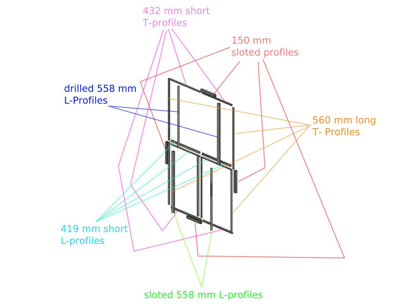
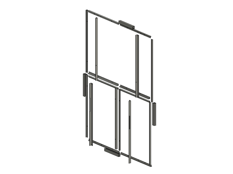
- 4 x L-Aluminium profile, 558mm (l) x 20mm (w) x 2mm (th)
- 4 x Squared aluminium profile (better rectangular profiles with 20mm x 8mm), 150mm (l) x 20mm (w) x 2mm (th)
- 4 x T-Aluminium profiles, 560mm (l) x 15mm (w) x 15mm (h)x 2mm (th)
- 4 x T-Aluminium profiles, 435mm (l) x 15mm (w) x 15mm (h)x 2mm (th)
- 2 x L-Aluminium profiles, 545mm (l) x 15mm (w) x 15mm (h)x 2mm (th)
- 4 x L-Aluminium profiles, 420mm (l) x 15mm (w) x 15mm (h)x 2mm (th)
- 24 x Hexagonal bolts, M3 x 8mm (l)
- 24 x washers, M3
- 24 x Self-locking nuts, M3
- 36 x Countersunk bolts, M5 x 10mm (l)
- 36 x Self-locking nuts, M5
- 36 x washers, M5
- 8 x Wing bolts, M6 x 20mm (l)
- 4 x Semi-flexible mono-crystalline PV-modules, in this case, we've used the SUPERFLEX SGM-FL-35W, 12 V, 35 Wp
For cables:
- 1 x Female M4-plug
- 1 x Male M4-plug
- 3 x Heat shrink tubes (short), for 4 mm² cables
Outils
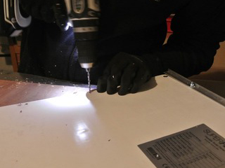
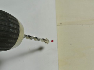
Étape 1 - Drill the PV-module needs
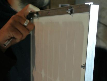
You can find the positions and diameter of the holes in the .PDF technical drawing which you can download below. For marking those of the PV-modules use a marker pen. For drilling use a metal or wood drill. Two of the 20mm-L-profiles need to have a slot cut along one side; the position of the slots is shown in the .PDF technical drawing downloadable below. These slots will allow the angle of incidence can be adjusted. To slot the profile you should use a milling cutter.
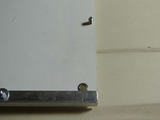
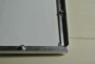
Étape 2 - Connect the profiles on the backside of the modules
After drilling, connect the profiles on the backside of the modules with the M5-10mm countersunk bolts, nuts and washers. Take care to place the washer on the side of the nut.
Étape 5 -
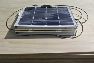
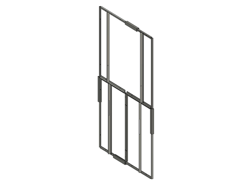
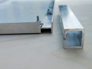
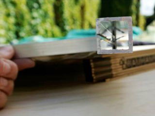
When the panel assembly is unfolded, it is held open and flat using the 15 cm long squared aluminium profiles that were cut open on one side. These slide on over the T-profiles from a corner of the unfolded assembly and sit in place halfway up the side of the assembly, as shown.
Étape 6 -
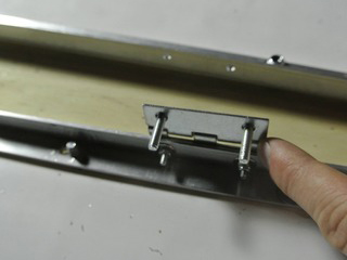
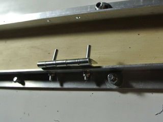
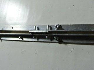
The cut square and T-profiles both fit together.
You already drilled fastening holes in the T- and L-Profiles according to the instructions in Step 3 “Preparing the Aluminum Profiles”. The holes to attach the hinges in the L-profiles are different, because they need to be placed according to the hinges you have, and this will vary. To mark the position, place the hinge 5 cm from the end of the profile not on the side of the other holes, like you can see it in the following picture. Then mark the holes with a metal marker.
Étape 7 - Solar Module Cables
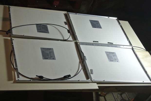
After the solar modules are connected to the folding mechanism, their cables need to be connected and fixed. The first step is to bring the cables to the backside of the solar panels. Drill holes as you can see near to the connection box of the panels. Afterwards you can push the cables to the other side.
Étape 8 -
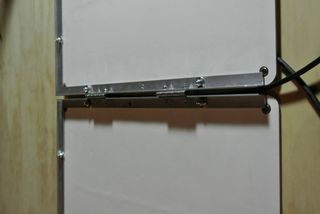
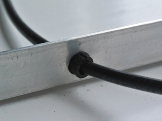
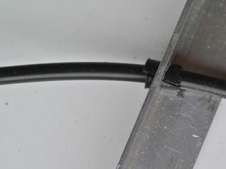
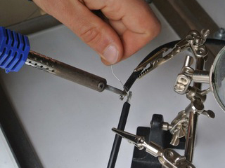
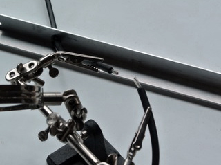
The cables need to be soldered in series as you can see in attached wiring diagram. So you connect the positive pole of one panel with negative pole of the following. To do so you have to lay the cables in some cases through the profiles in between. So that they are not squeezed when the panels are folded. Therefore, drill a hole through the profile and push the cable through. Protect the cable and hold it in position in the hole with small piece of rubber. Insulate the soldered connections with the heat shrinking tubes.
Étape 9 -
At the end you have to connect the appropriate M4 plug at the positive and the negative pole, respectively.

 Français
 English
 Deutsch
 Español
 Italiano
 Português