Matériaux
For the Solar Box Lid:
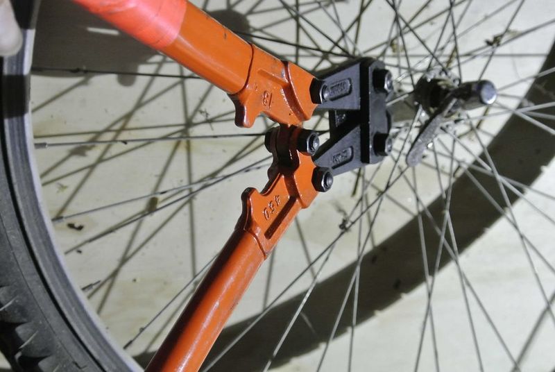
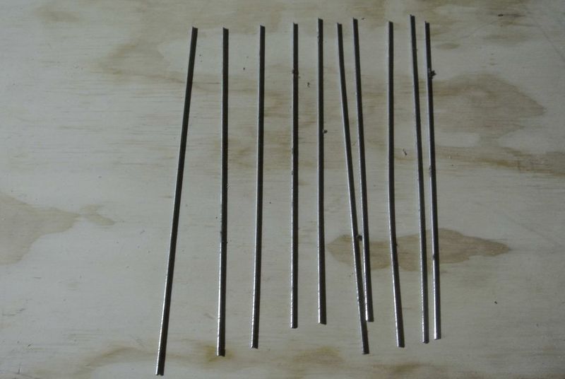
- 8 x Bicycle spokes, around 150 mm long
- 1 x Plywood, Min. 1200 (L) x 400 (W) x 18 (th)
For sockets and Switches:
- 2 x LED (Green)
- 1 x Switch, DC
- 6 x Female Connector WEIPU SP21 (These are what we used in our prototype, but we actually do not recommend to use the Weipu sockets and plugs as they easily slip out of the boxes)
- 1 x DC-switch
- 1 x ¼ EURO norm box, with lid, 742mm (H) x 600mm (L) x 400mm (W) (Usable: 732mm (H) x 570mm (L) x 370mm (W)
- 2 x 1/8 EURO norm box, with lid, 230mm (H) x 400mm (L) x 300mm (W) (Usable: 208mm (H) x 370mm (L) x 270mm (W)
Outils
Étape 1 - Preparing the Solar Box Lid
Take the ¼ EURO norm box with lid.
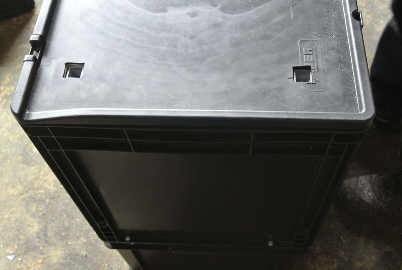
For the mounting system of the solar panels holes in the lid of the solar box are required. In this way the square profile of the mounting system can move in and out of the box.
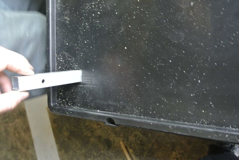
To do this holes first close the lid of the box with the mounting system inside give it a light knock with a rubber hammer on the lid surface where the tops of the mounting structure contact the inside of the lid. The plastic of the lid will dent outward forming square marks showing the position of the vertical profiles of the inside structure.
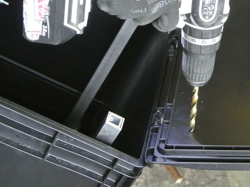
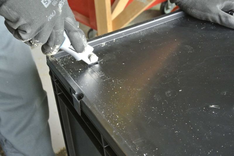
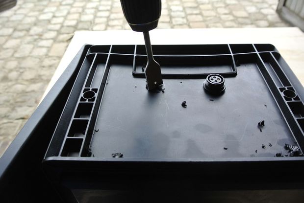
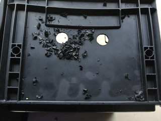
Now you can drill holes in the middle of the marked squares and cut them out with a cutter. Be as precise as possible.
Étape 3 - Box Joins
To physically anchor the the boxes together, the joins need to be added. The joins hold the boxes in place on a wooden foot structure. This structure can be CNC-milled with the provided .DMX source file, which you can download below. You can also old-school wood-craft them, following the .PDF technical drawing, also downloadable below.
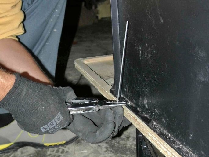
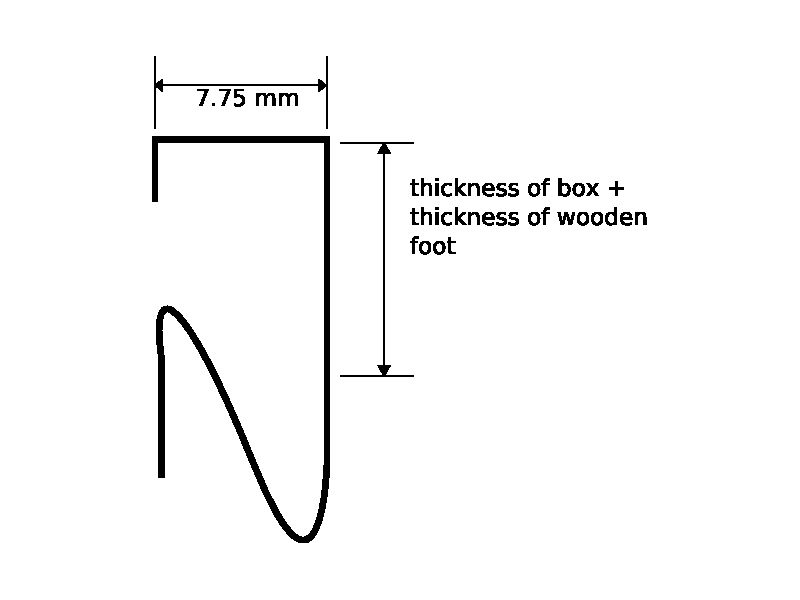
After milling the foot structure, put the boxes in their places and drill 4 holes through the outside bottom rim of each box and the underlying wooden structure. Using these holes, the different parts are connected by a bent bicycle spoke. The shape of the spoke can be seen in the following figure.
The shape of the spoke can be seen in the following figure bellow.
The height of the “mouth” of the bent spoke depends on the thickness of the wooden foot (see diagram). It should 2-4 mm less than the added thickness of the box and the wooden foot. To bend the spoke, start from one side of the spoke and do one bending after the other by holding the spoke with pliers and bending then the longer end of the spoke with your hand in the shape you like.
Étape 4 - Sockets and Switches
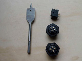
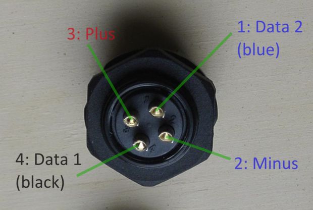
The order of the different pins of the plugs and sockets can be found in following photo. Connection one is for 1st communication (blue cable), two is minus, 3 is plus and no 4 is the 2nd communication (black cable).
Étape 5 -
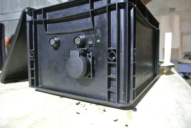
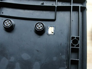
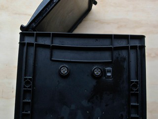
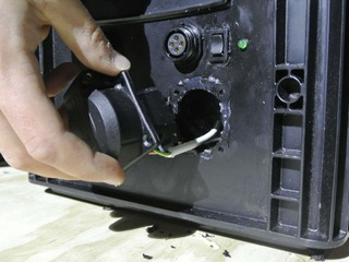
Switches and sockets To insert the switches, sockets and the LEDs to the boxes, first the holes on the outside of the box need to be drilled and/ or cut for the switches and sockets respectively. Use 22mm- Drill to drill the holes for the sockets and a 5mm drill for the LEDs. For the switch and the AC-socket, first mark the position and the dimensions of the switch, then drill a small hole inside this dimensions and finally cut the hole out with the cutter.
Étape 6 -
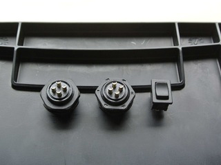
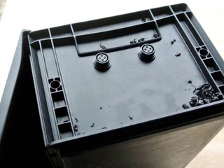
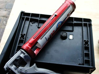
Once the holes are done, the sockets can be attached into them, by placing them from the outside with the thread ahead into the hole and then screw them tightly with the nut from the inside. The switch also needs to be inserted into the hole from the outside with the contacts ahead. Afterwards, the connection between the switch and the box needs to be made waterproof with silicon.
Étape 7 -
All these components should be located in the upper third of the boxes, and centred in the façade. In the case of the solar box, they should be horizontally centred on the longer side, where there the two horizontal profiles of the inner structure (as in the below diagram). For the battery- and inverter/socket-box, they should be horizontally centred on one of the shorter sides.

 Français
 English
 Deutsch
 Español
 Italiano
 Português