Sommaire
- 1 Étape 1 - Make components
- 2 Étape 2 - Cut the lids for filter
- 3 Étape 3 - Cut the compression disks
- 4 Étape 4 - Cut the Fabrics
- 5 Étape 5 - Caps for UV lamp
- 6 Étape 6 - Cut the Filter Housing Pipe
- 7 Étape 7 - Make waterproof gaskets
- 8 Étape 8 - Assemble the flow regulators (1)
- 9 Étape 9 -
- 10 Étape 10 - Then do the lid on the other side.
- 11 Étape 11 -
- 12 Étape 12 -
- 13 Étape 13 -
- 14 Étape 14 - Place the lid on a flat surface and add the pipe
- 15 Étape 15 -
- 16 Étape 16 -
- 17 Étape 17 -
- 18 Étape 18 -
- 19 Étape 19 -
- 20 Étape 20 -
- 21 Étape 21 -
- 22 Étape 22 -
- 23 Étape 23 -
- 24 Étape 24 -
- 25 Étape 25 - Tada!
- 26 Commentaires
Étape 1 - Make components
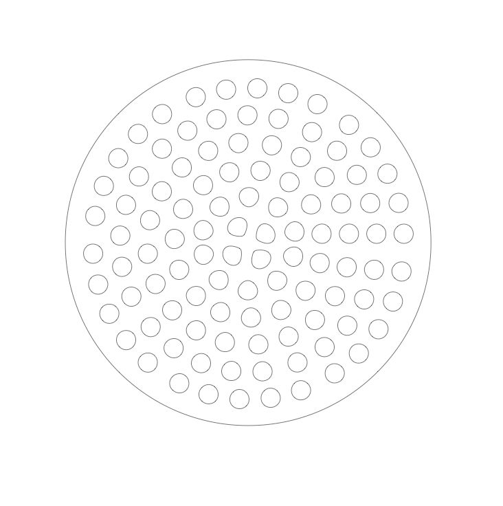
Laser cut or CNC the files in this pdf.
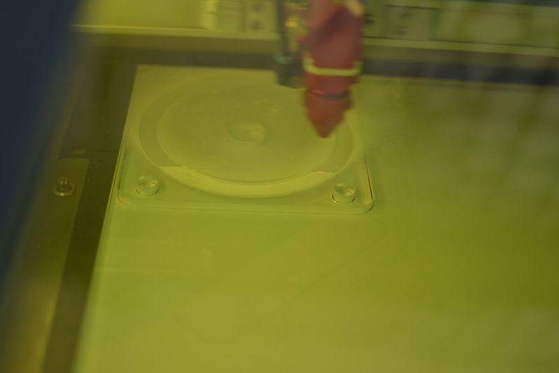
Since laser cutters handle cutting a bit differently there may be come problems with the file. Generally red / hairlines (0.001mm) is for cutting and black is for engraving.
The lids and mounting plates can also be a single piece if you are using thick material. Four 10cm diameter x 50cm filters are required to have an appropriate flow rate of 10l/min. With 6.6l/min two filters are sufficient and 1 filter for 3.3l/min. The surface area is more important than the length of the filter because that determines the flow rate through the filter and thus reaction times. I use 10mm thick acrylic sheets for the lid and compression disks but I have used 4-5mm acrylic sheets in previous prototypes and glued them together with decent results.
Étape 2 - Cut the lids for filter
There are 2 lids per filter, the top lid and bottom lid - duh.
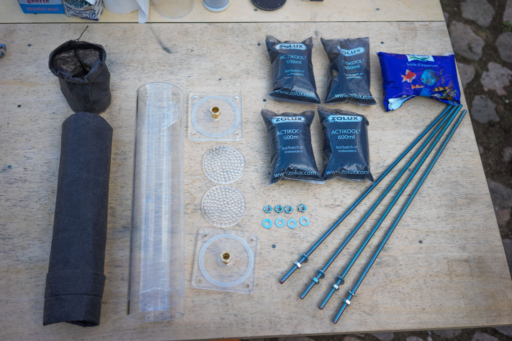
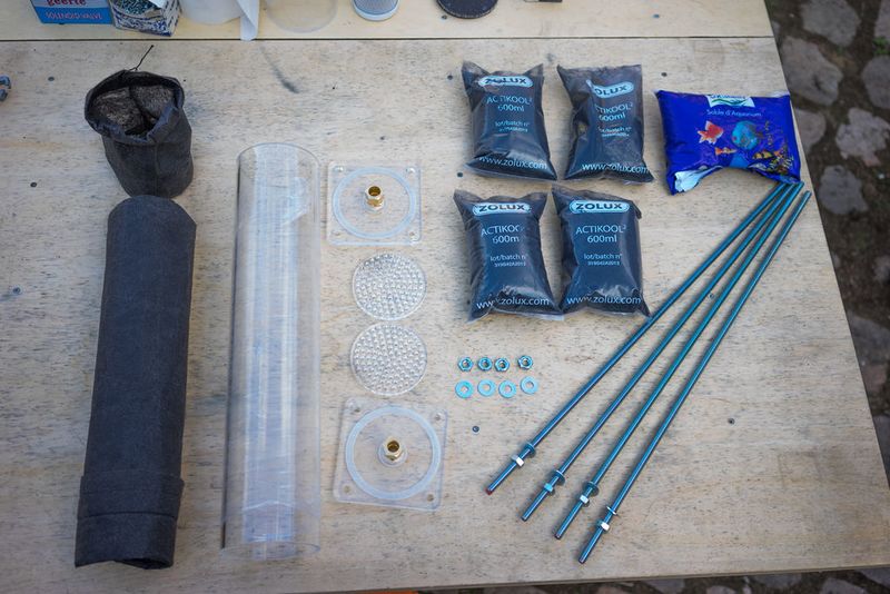
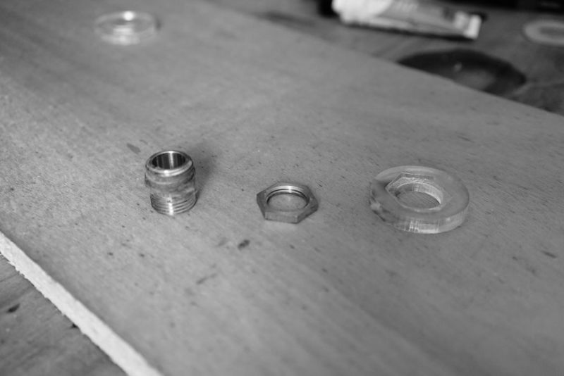
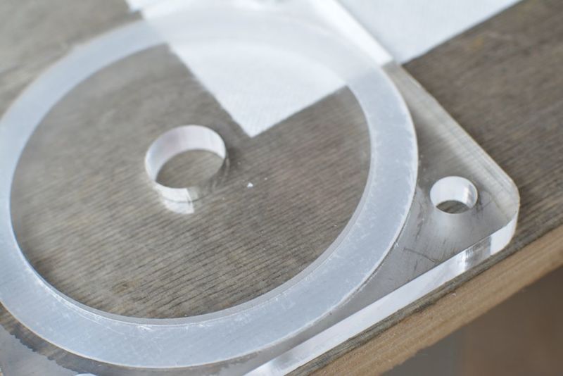
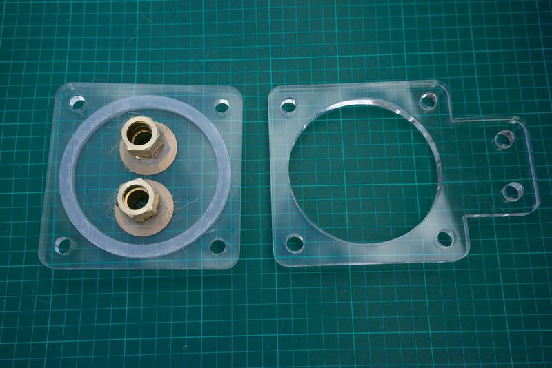
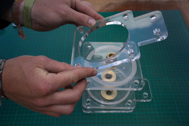
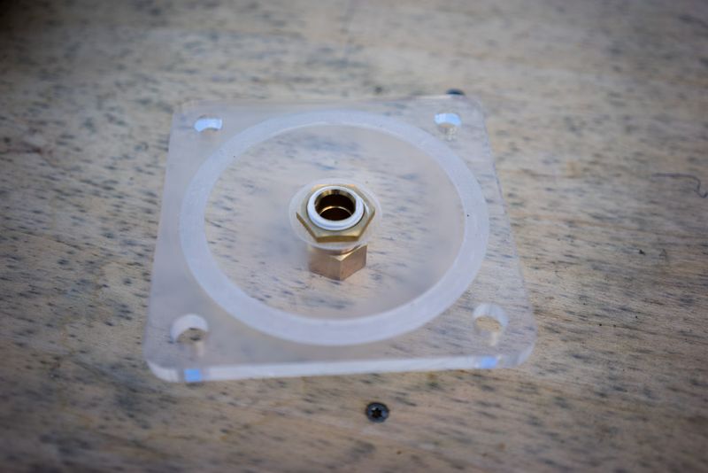
A hex nut is used to fasten the hose nipple (facing away from the filter) to the filter lid. The dimensions of hex nuts and/or hose nipples may vary regionally so it's best to get them first,check the measurements and modify the file if needed. In the picture of the lid only a circle was etched/milled into the acrylic lid to fit the hex nut but the design was later revised to have the shape of the hex nut itself, thereby fastening it to the lid so that it could no longer rotate (and prevent fastening) when adding the hose nipple on the outer side of the lid.
Étape 3 - Cut the compression disks
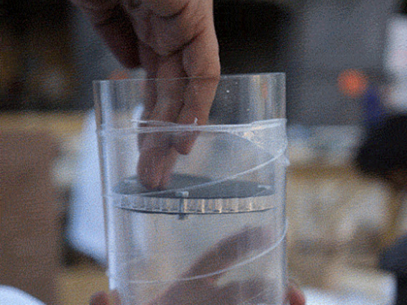
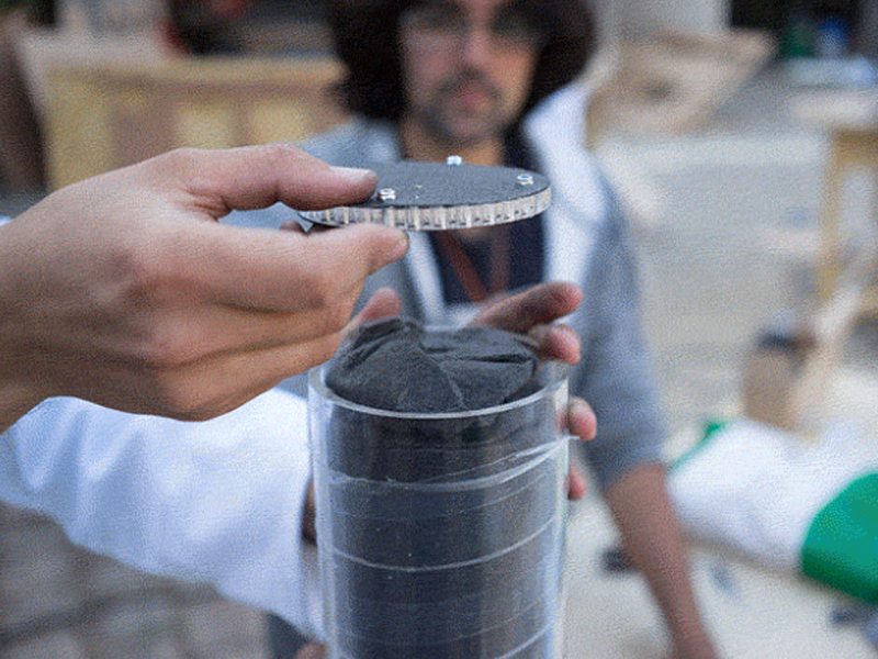
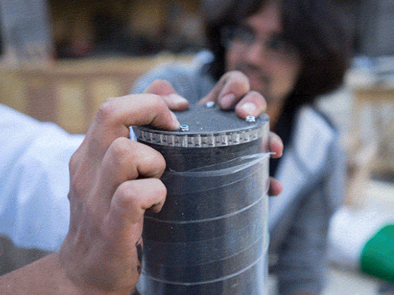
There are 3 compression disks per filter. Two on both ends for squeezing in the sand and activated carbon and one in between the sand and activated carbon! The compression disk in the file is nested inside the void of the mounting plate to save materials!
Étape 4 - Cut the Fabrics
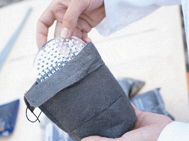
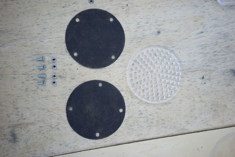
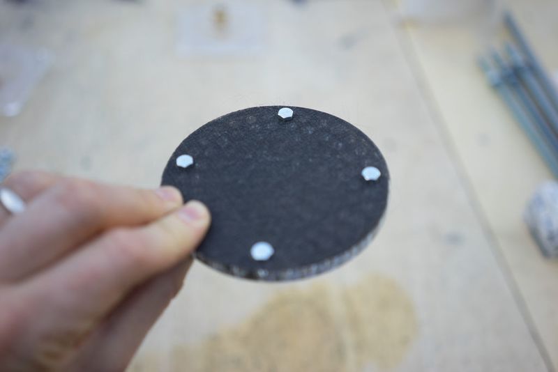
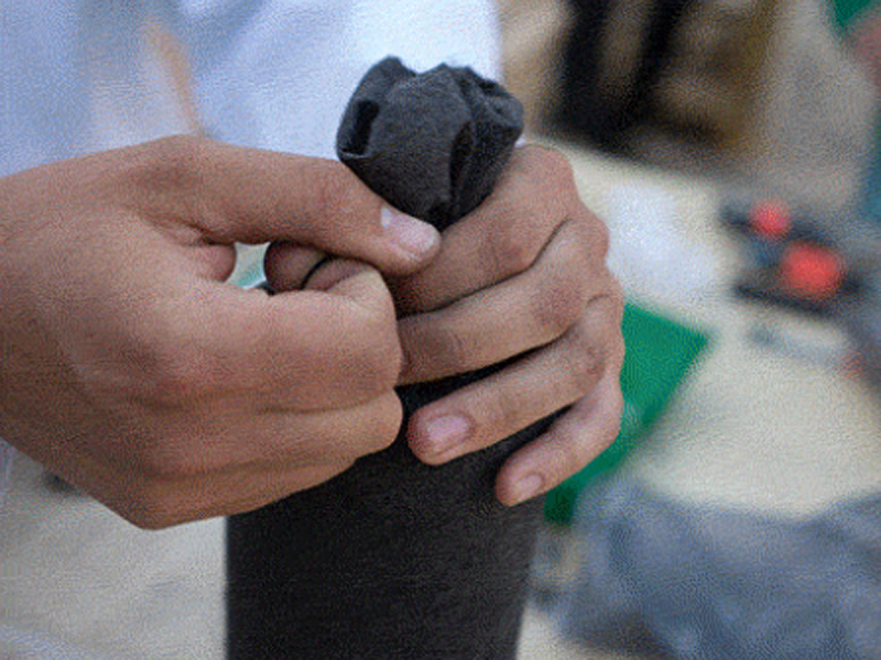
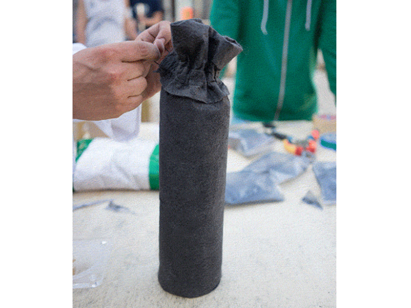
3 per filter. Width should be 10-15% larger than the inner width of the filter housing, in this case it's 115 mm. Lasercut (low power) or scissor cut the fabric membrane.
Lids for flow regulator The flow regulators are just like the filters but with a single input and multiple outputs for the bottom flow regulator and vice versa for the top one.
Étape 5 - Caps for UV lamp
The cap is on the far right. A dip is etched into it to fit the hexnut/lock nut in the same way as in the filter lid. The Male-male brass union fastened to the UV cap is what allows the water tight connection between the UV lamp and piping. Special care should be taken with this UV cap because Acrylic will still let UV light through, while not included in the following picture sets the outer side of the cap should be coated in white paint (with titanium dioxide) or otherwise taped up so that you don't get exposed to the light directly.
Étape 6 - Cut the Filter Housing Pipe
Cut the transparent acryclic pipe with a band saw if available or with a hand saw.
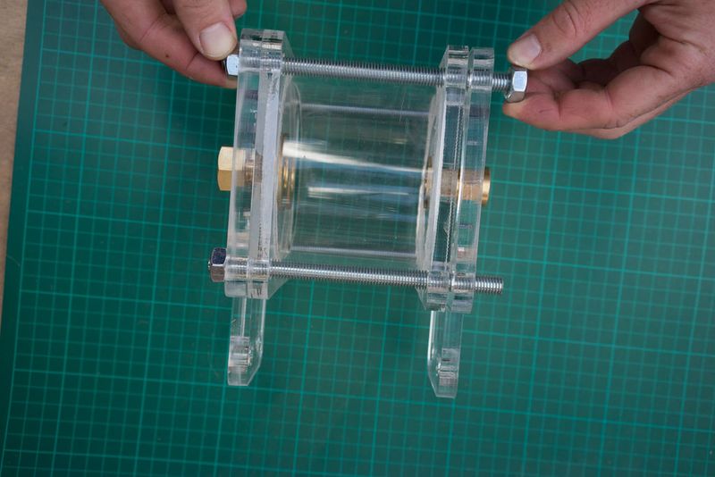
The filter housings should be 55 cm long and the flow regulator pipe should be around 10 cm long but shorter bits may work just as well and therefore require less water. The flow regulators can be left out of the build completely but there's something great about being able to see dirty water in the lower one get cleaned up by the filters and to get visual feedback in the top one which should be around eye height.
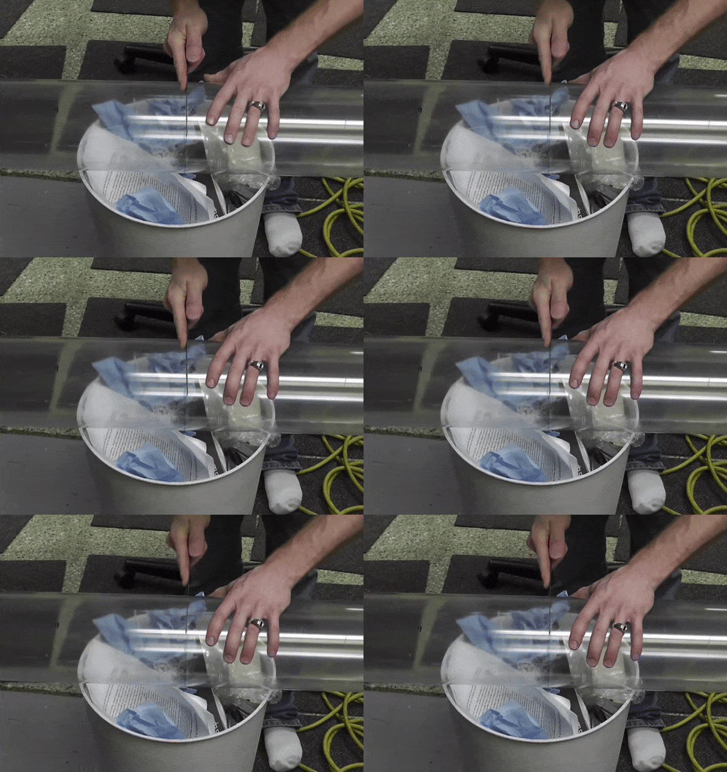
To get a straight cut the following videos are pretty helpful. The gist is to use lined up tape to get a perfect straight line around the pipe and cut around them. With a band saw you can use the leveller (aligning tool) to keep the cut straight. Because acrylic works a lot like wood you can level or adjust the cutting with sandpaper.
Étape 7 - Make waterproof gaskets
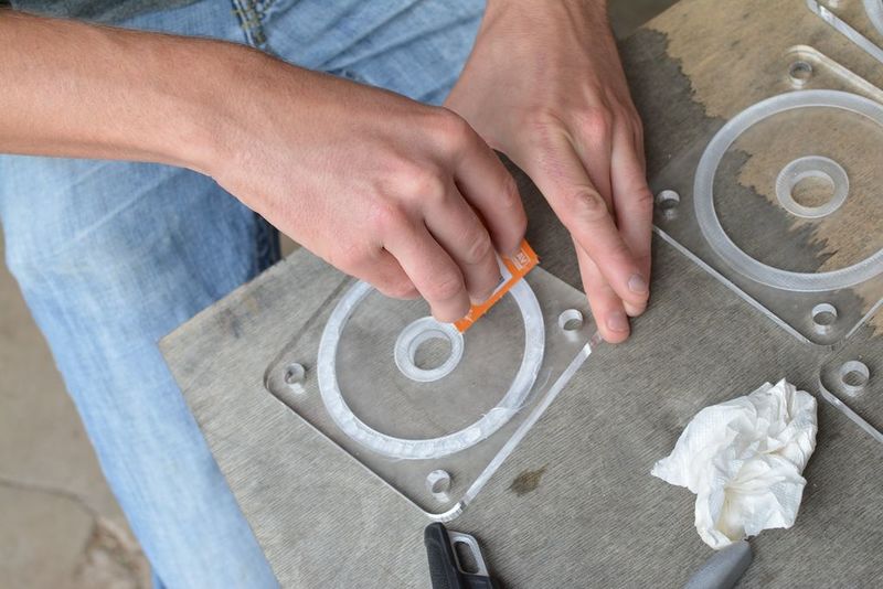
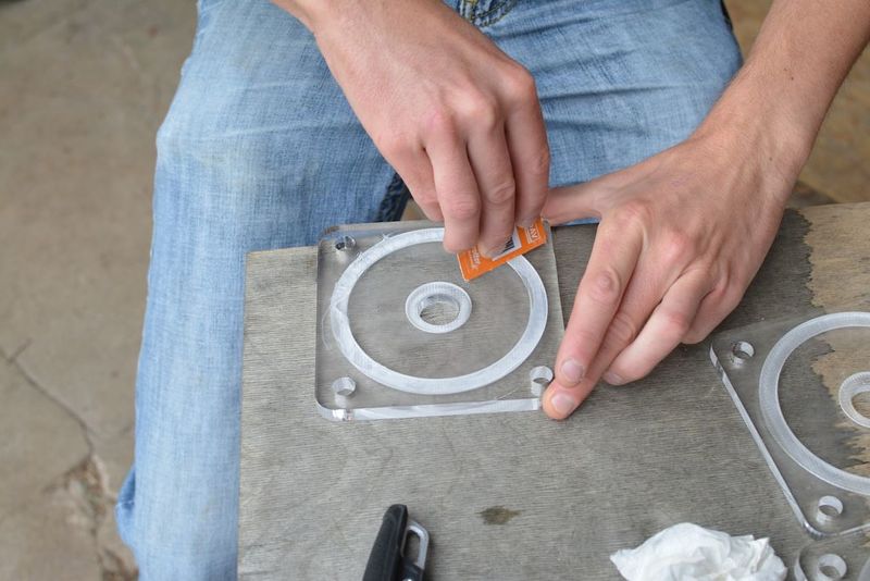
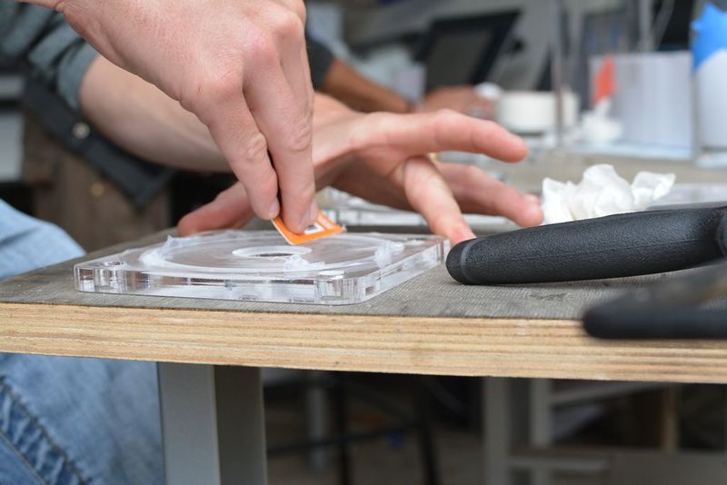
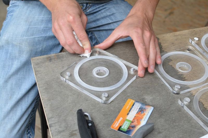
This step can be skipped by milling a gasket out of silicone sheets with the same depth as the 'trough' in the lid. I don’t have much advice on material selection (rubber or silicone) but there are specialist stores that could provide solid advice. I use silicone sheets. The material is best laser cut to the dimensions of the trough mentioned above. The .ai file can be found above (Gasket.pdf) Using a ‘silicone gun’ fill the circular trough with silicone up to the surface level. Use a plastic card such as a membership card you don’t mind getting a bit dirty, and with force, slide the flat surface across and over the silicone. It’s ok if it goes over or gets dirty as it can be cleaned later. Make sure that there are no bubbles or distortions in the silicone. The surface of the lid can now be cleaned toilet paper but avoid areas near the trough until it has hardened ~24 hours later. The silicone is easier to rub off once it’s dry.
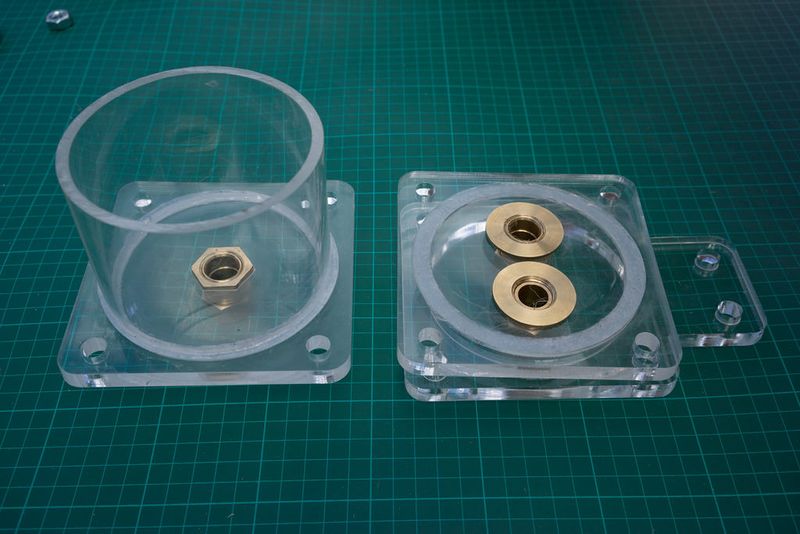
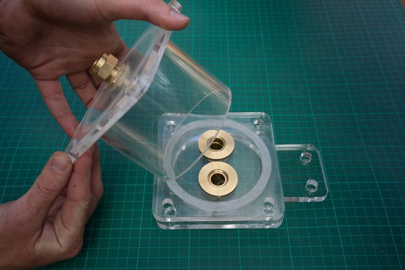
Use a gasket or silicone in a similar fashion as mentioned above to connect the lower lids to the tubes. Fill the trough as mentioned in the steps above but instead of letting the material dry, press the cylinder into the lid, clamp together and then leave to dry (24 hours ideally). The silicone can be smoothed out with a gloved finger. This also reduces the surface area for bacteria or dirt to attach too. The water pressure is highest at the bottom of the filter, and so fusing the tube together with the lower lid is a good idea since it makes the seal extra strong.
So the top lids for the filters and flow regulators are the removable ones that are allowed to dry, but the lower lids can be sealed together. If you use a milled gasket the filters will hold up on their own without the need for any silicone, but assembly is easier when one side is attached. It's also possible to use acryclic glue and chemically bond the materials together, but usually costs a lot more than silicone. It should last longer than the silicone on the other hand.
Étape 8 - Assemble the flow regulators (1)
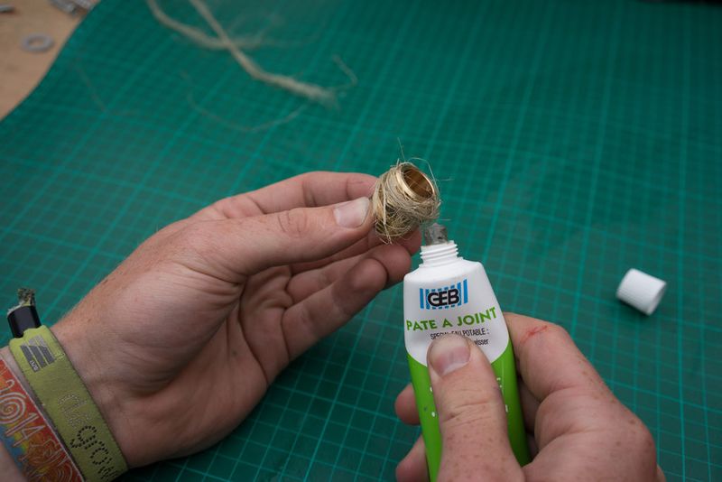
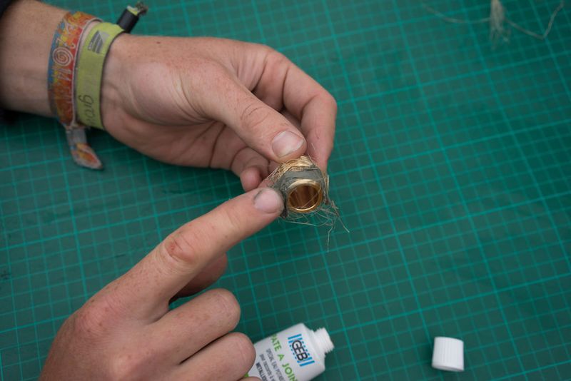
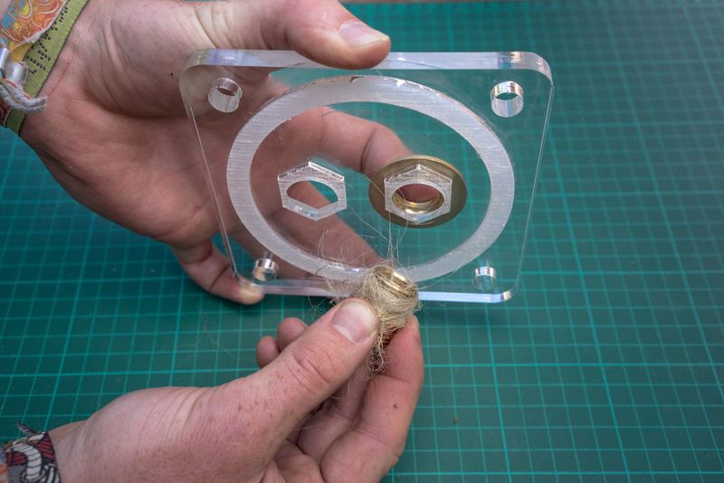
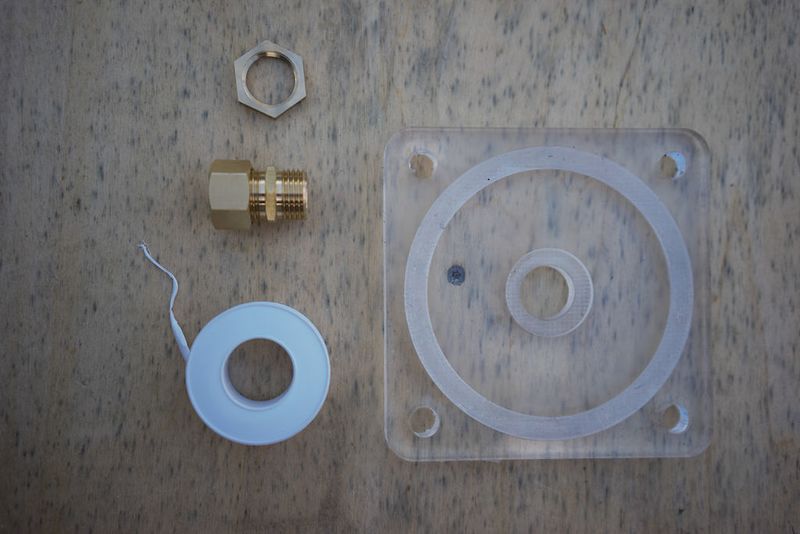
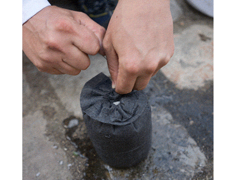
This part may take some practice figuring out just how much fibre to use. You can also replace the fibre with teflon tape (pipe tape) and as a rule of thumb I do about 8 layers (times around) but it depends on the size of the hole.
Étape 9 -
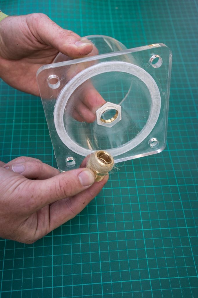
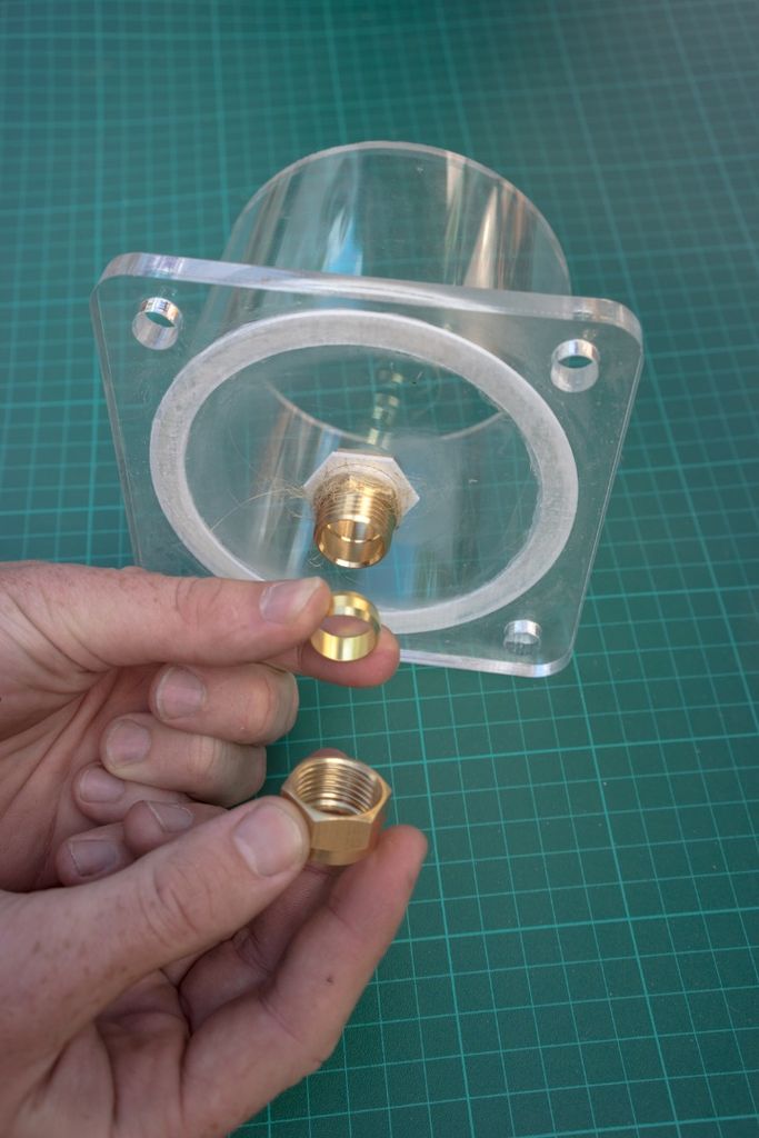
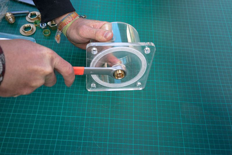
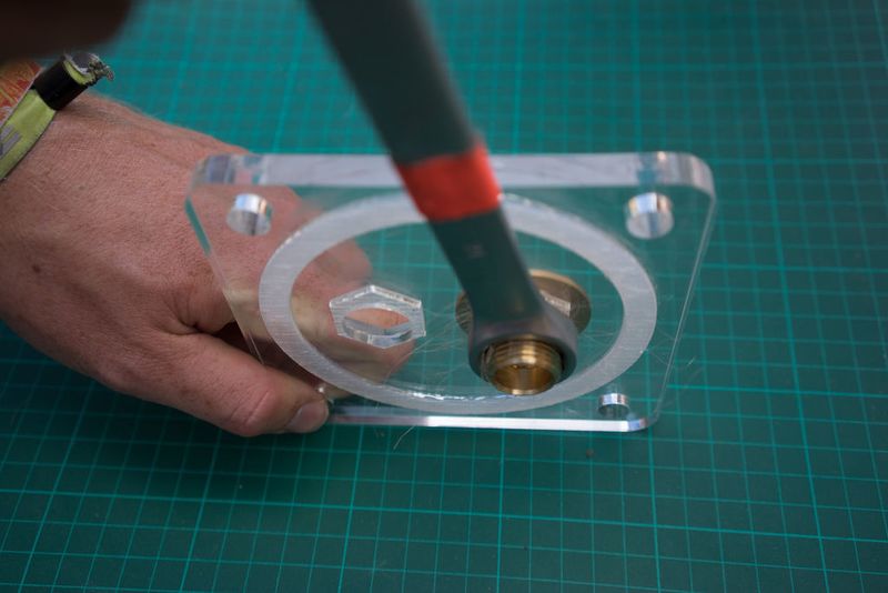
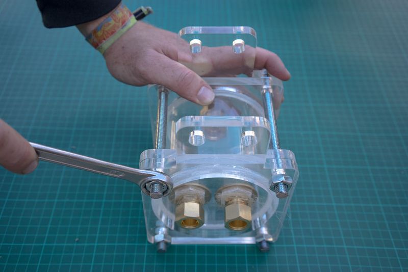
hold the lock nut in place while using a spanner to tighten the union to the lock nut. a hose nipple can also be used instead of the copper union.
Étape 13 -
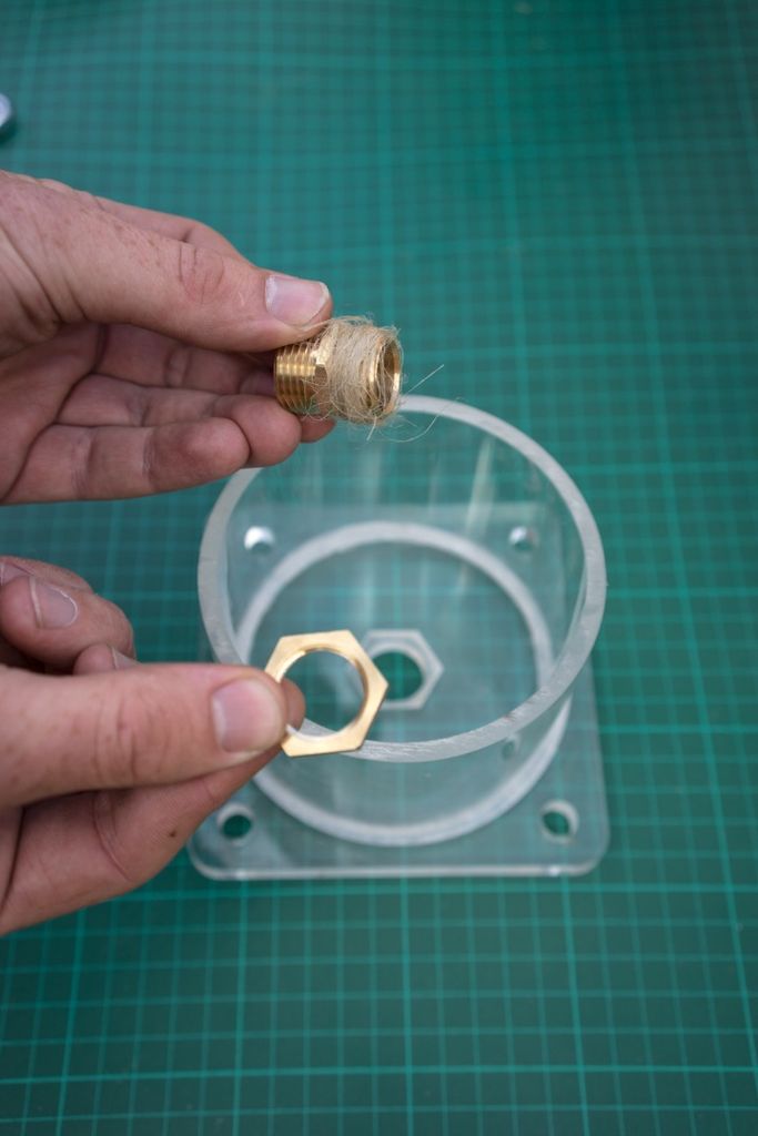
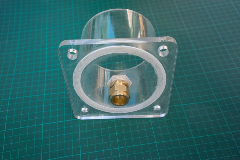
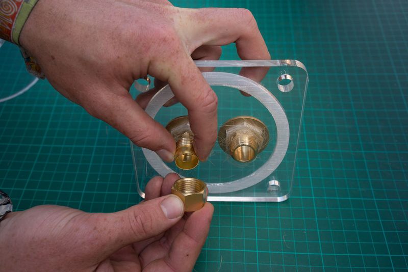
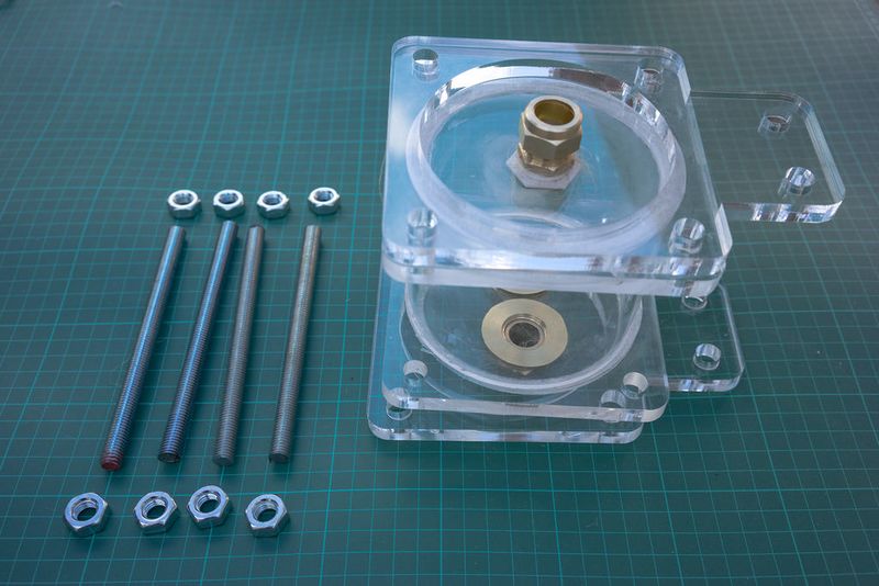
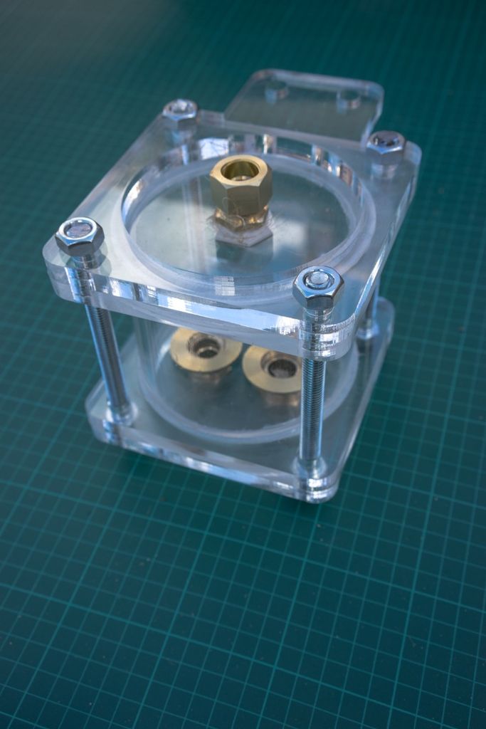
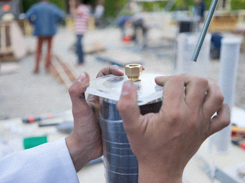
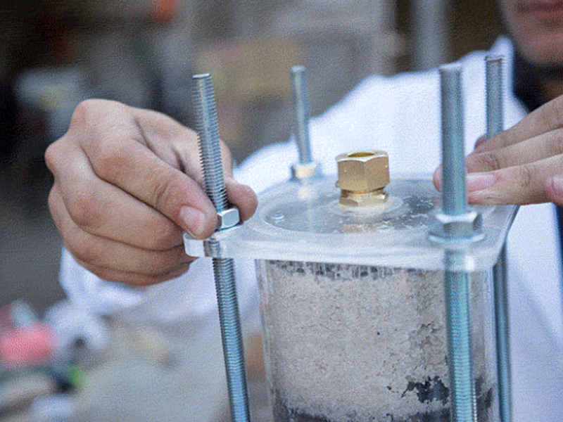
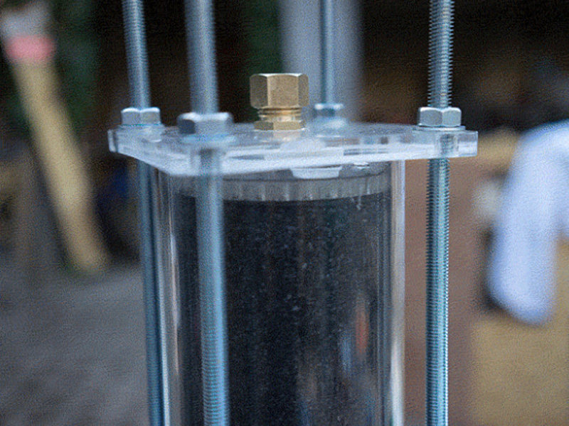
Slot the hexnut into the groove in the lid and screw in the brass male-male union (or male thread hose connector) on the flat outer side of the lid.
Use hemp fibre and mineral oil or a lot of teflon tape around the union and hex or + use silicone to seal the thing for good.
Do this for both lids.
Étape 14 - Place the lid on a flat surface and add the pipe
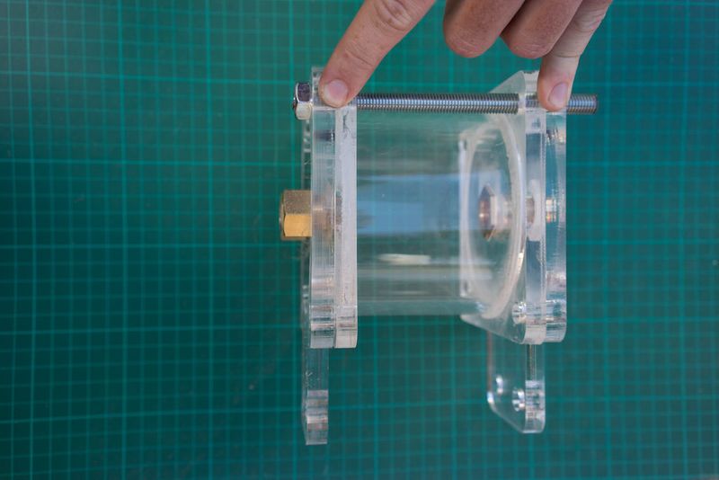
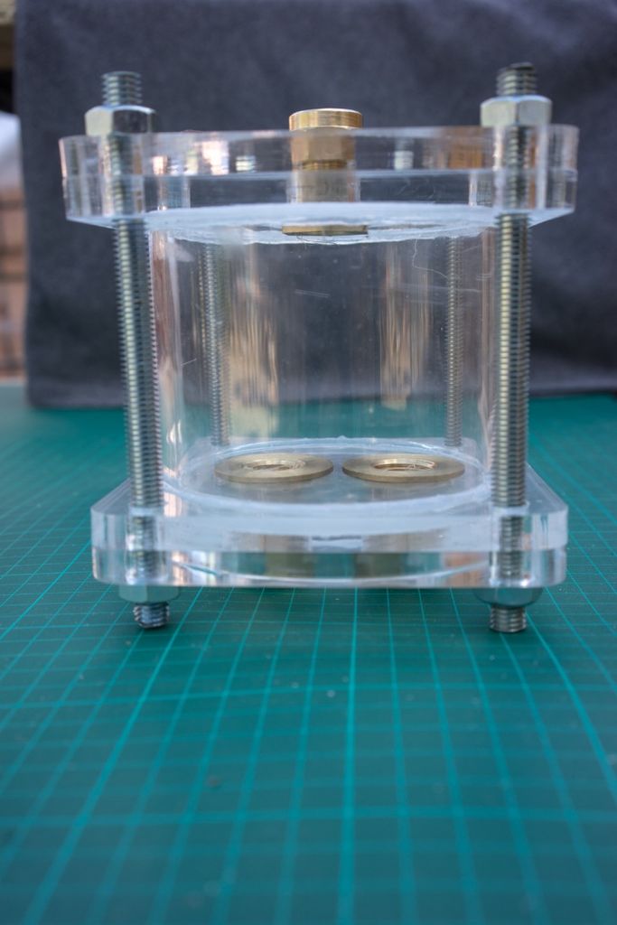
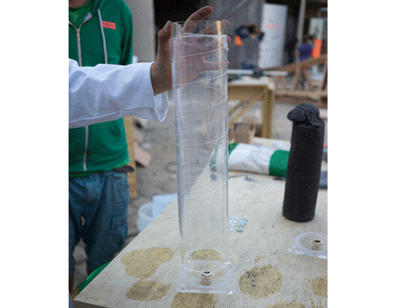
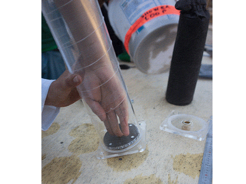
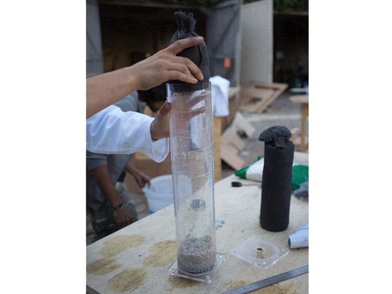
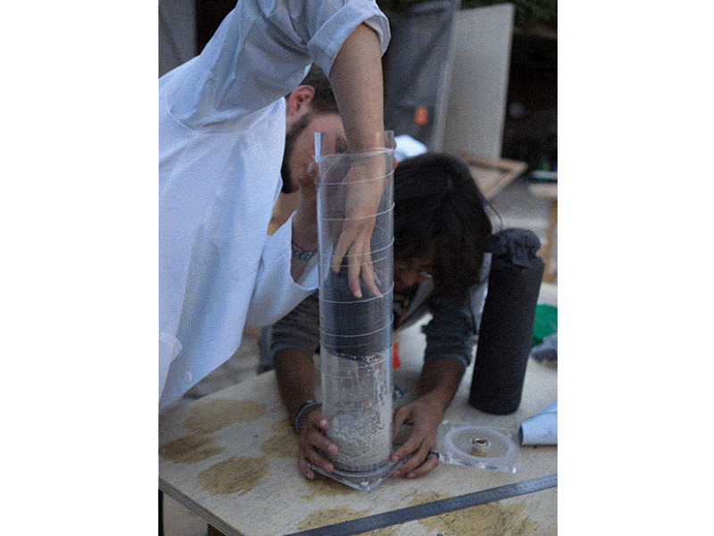
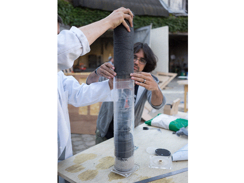
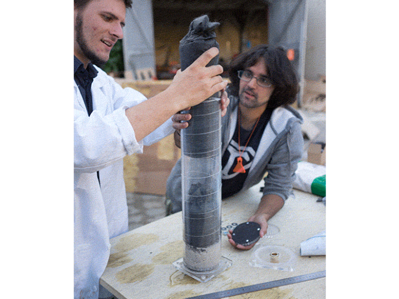
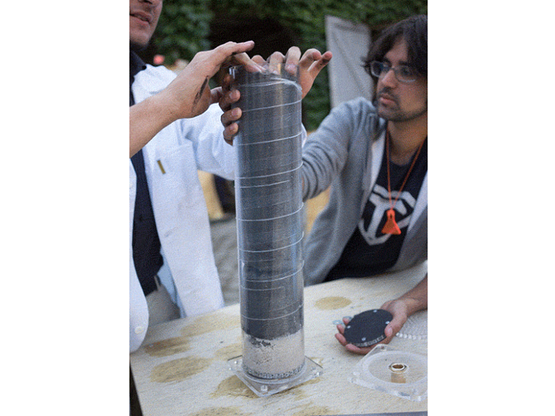
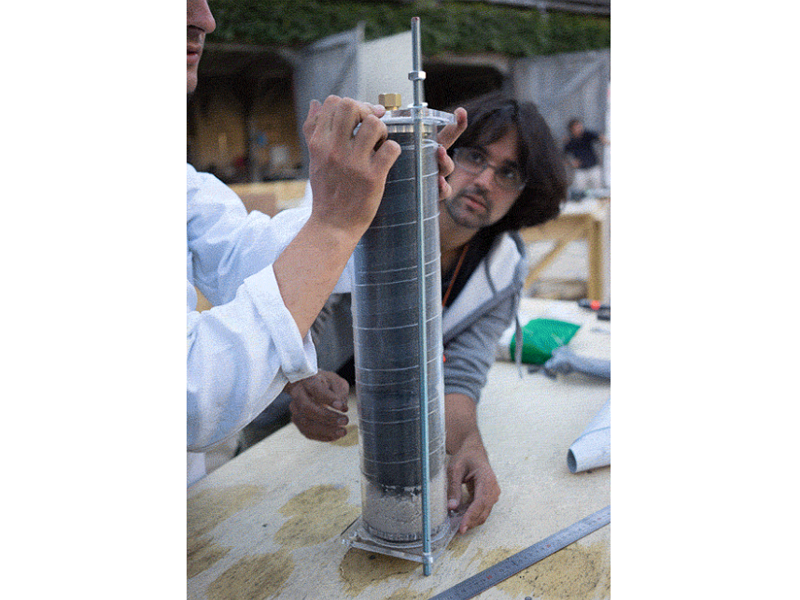
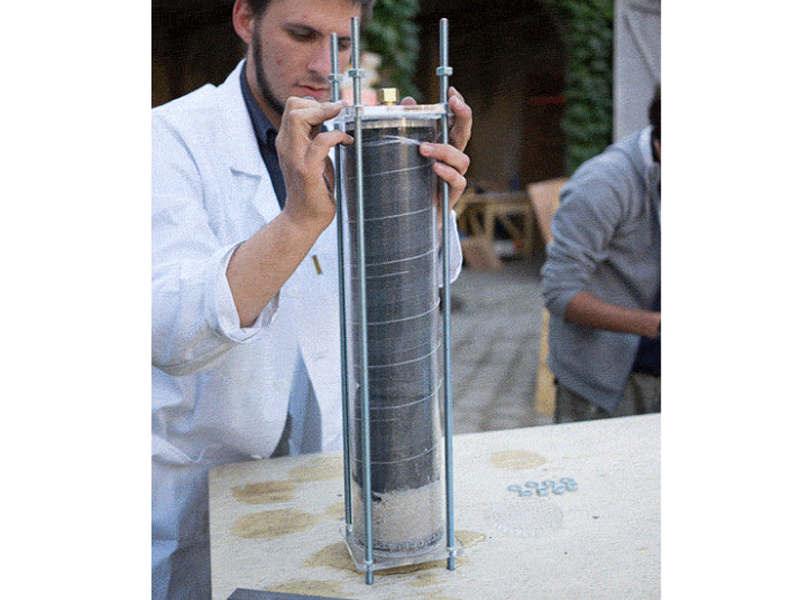
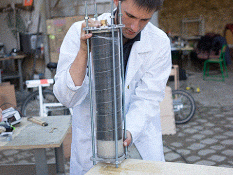
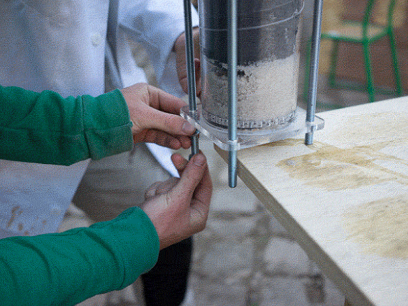
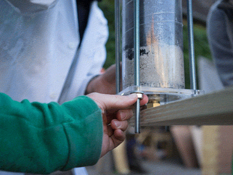
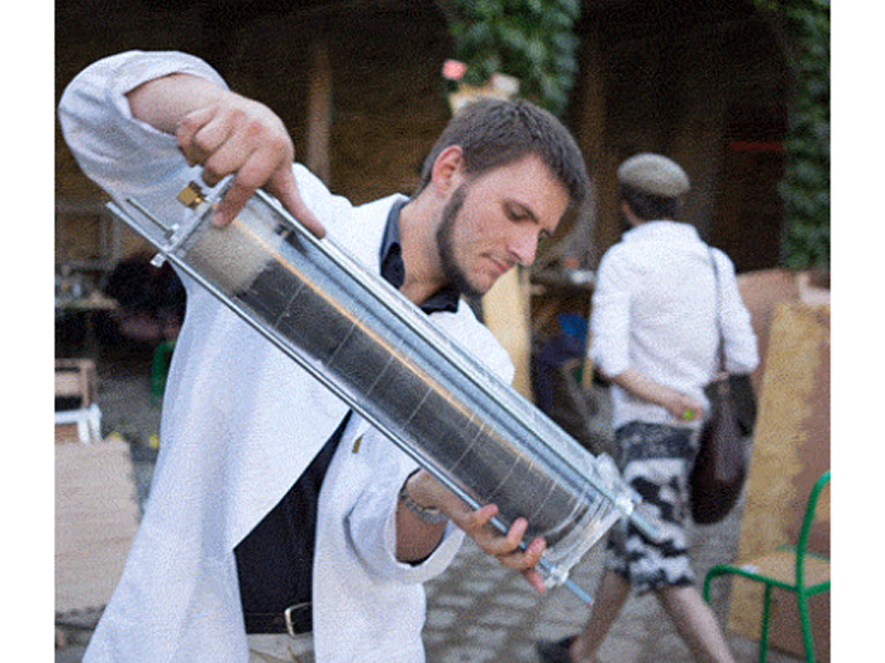
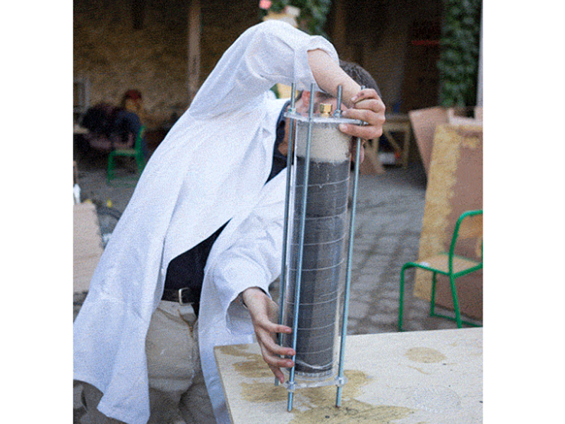
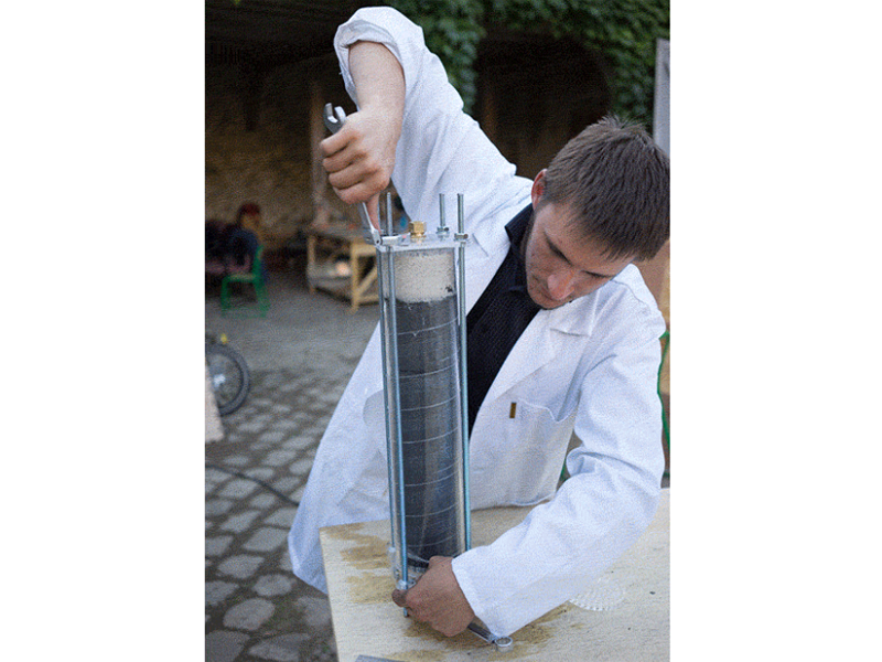
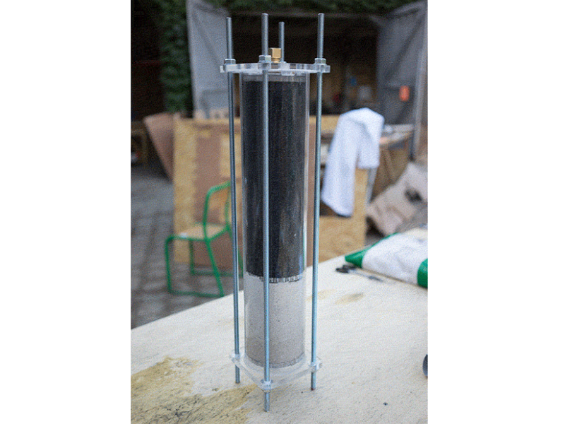
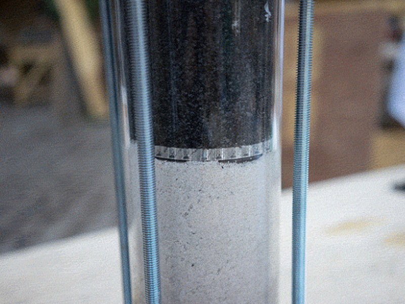
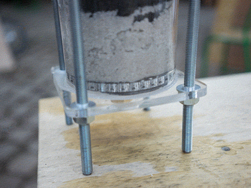
Place the bottom lid on a flat surface and add the 50cm pipe on top. Clamp it to the table or have someone help you.
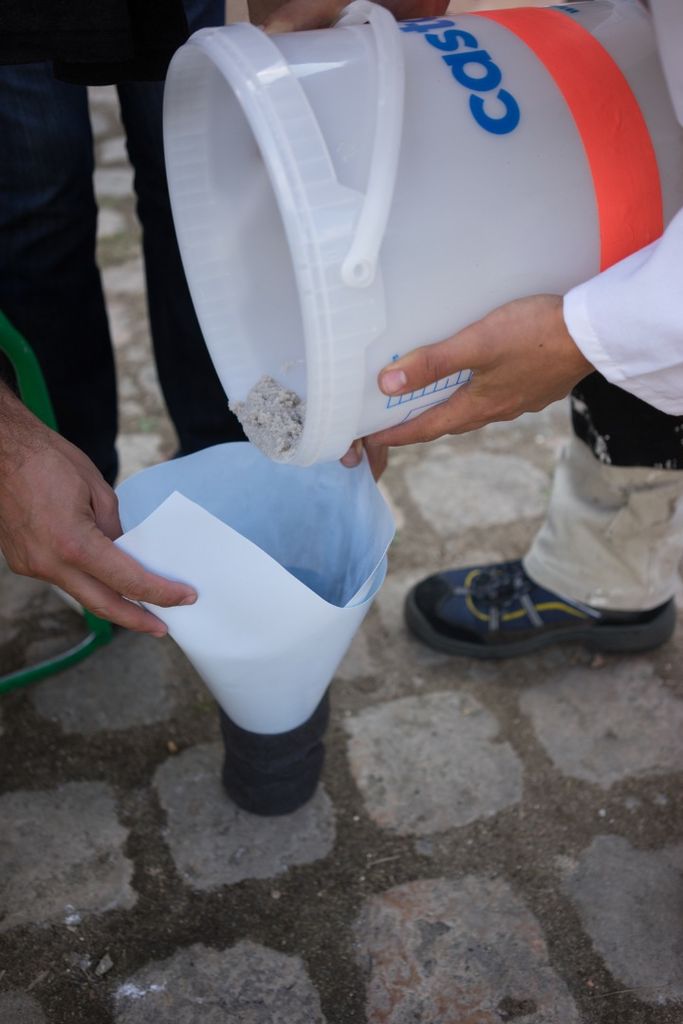
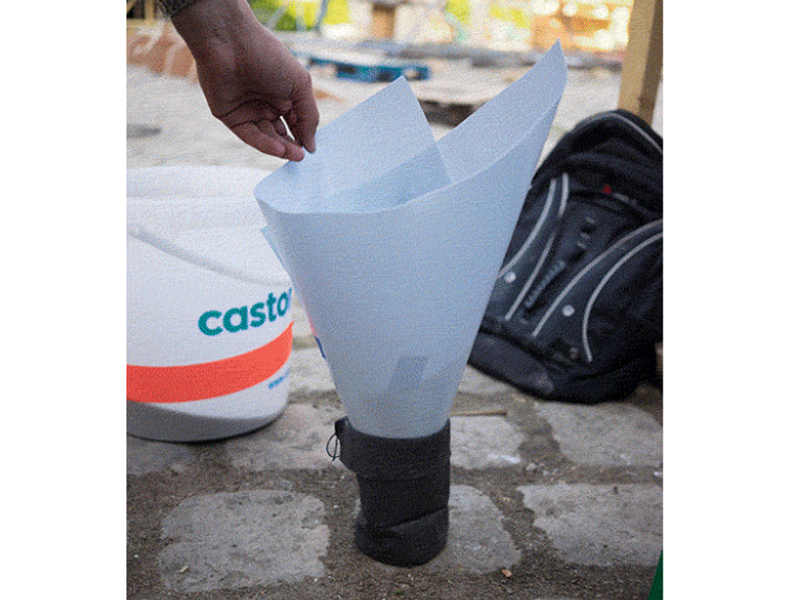
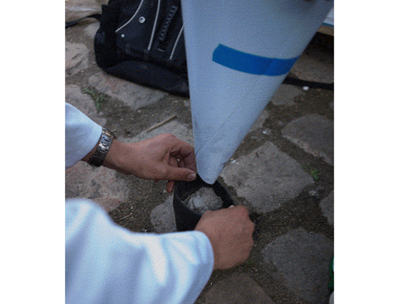
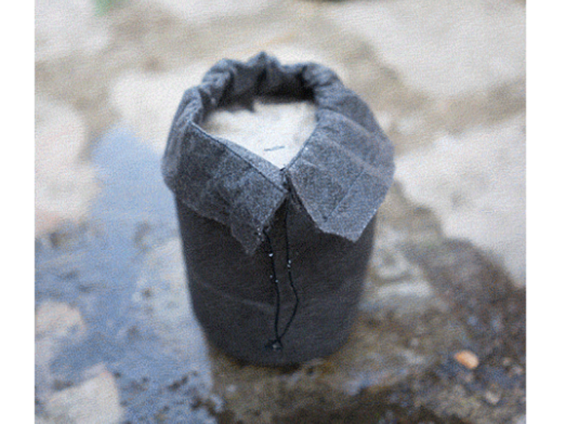
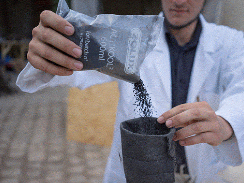
Insert the left over acrylic 'coins' from the laser cutting into the bottom lid (maybe glue them in). It's best to have two people for this step or use a clamp to hold the filter in place while adding the filtrates.
Étape 15 -
Insert the left over acrylic 'coins' from the laser cutting into the bottom lid (maybe glue them in). It's best to have two people for this step or use a clamp to hold the filter in place while adding the filtrates.




 Français
 English
 Deutsch
 Español
 Italiano
 Português