Matériaux
1x grosor del tablero de madera 5mm 610mm X 407mm
1x Arduino Uno http://www.lextronic.fr/P4124-platine-arduino-uno-rev-3.html
1x Bandeau Led verte https://www.led-flexible.com/led-flexible-au-detail/1007-bande-led-unicolore-vert-non-etanche-de-25m-au-detail.html
1x alimentation pile (pour bandeau à led) https://www.led-flexible.com/alimentation-led-12-volts/408-boitier-piles-extra-plat-pour-ruban-led.html
2x Moteurs DC http://www.lextronic.fr/P29728-motor-pack-dc25.html
1x Motor Shield http://www.lextronic.fr/P26224-platine-motor-shield-rev3-pour-arduino.html
1x capteur infrarouge 1x télécommande infrarouge http://www.robotshop.com/eu/fr/kit-infrarouge-pour-arduino.html
2x supports de pile (6 pile LR6 1,5Volt) (Alimentation principale Arduino Uno)
4x Piles 4,5Volts (2 pack montés en parallèle, chaque pack comporte 2 piles 4,5V montées en série) - (ça fait une alimentation sous 9V pour l’alimentation de puissance j’ai mis en parallèle pour avoir une plus longue autonomie)
8x Écrous M4 http://www.bricovis.fr/std/ecrous-9.php#Grille
8x vis M4 – 50 http://www.bricovis.fr/std/vis-tete-bombee-26.php#Grille
4x Entretoise M4 http://fr.rs-online.com/web/p/entretoises/9141006/
1x roue pivotante http://www.leroymerlin.fr/v3/p/produits/roulette-pivotante-a-tige-filetee-diam-50-mm-e21351#&xtmc=roulette_pivotante_a_tige_filete&xtcr=1
Outils
- Tournevis Cruciforme
- Clé Alen 1,5 mm (serrage des vis M3)
- pince de serrage (maintenir les entretoises et écrous)
Étape 1 - Planes
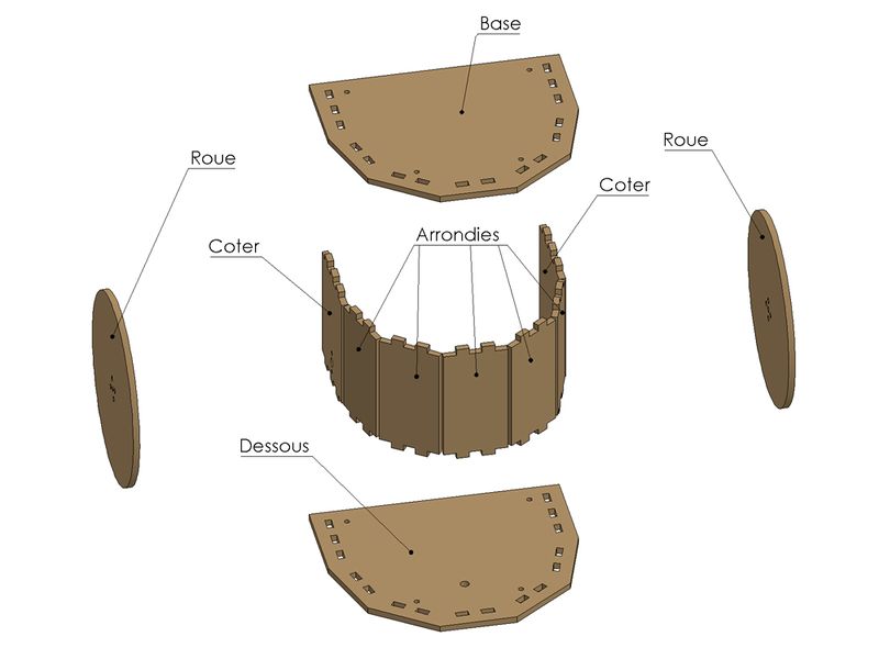
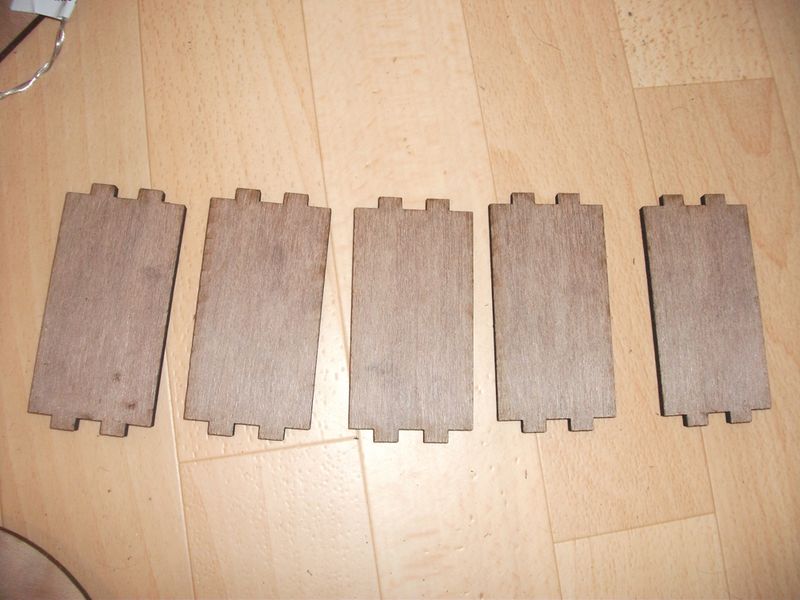
Aquí están los planos de cada pieza para realizar el robot con dimensiones (en mm)
Descargar archivos: https://framadrive.org/index.php/s/oHlHOqSsc18I4U1
Para usar una máquina de corte láser, vea la lista de FabLabs para encontrar la más cercana a usted: http://www.makery.info/map-labs/
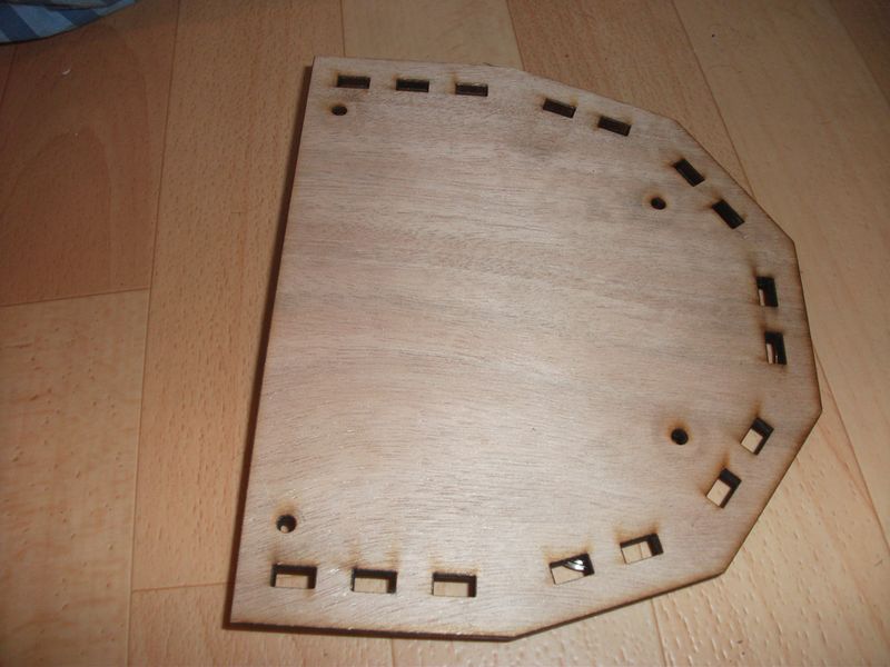
Étape 2 - Base
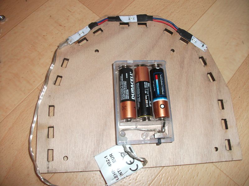
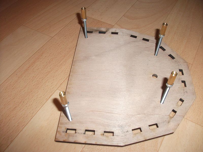
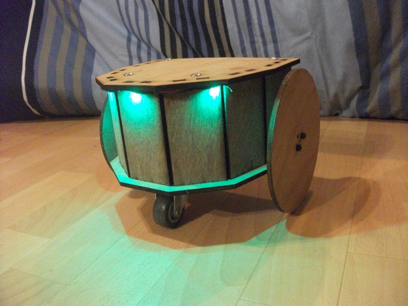
Empecemos por tomar la base añadiendo el soporte con su batería conectada a los 3 LEDs verdes.
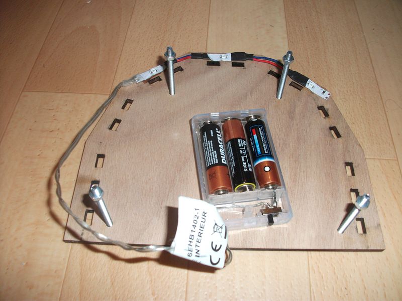
Tomar 4 tornillos M4 e insertarlos en los 4 agujeros y fijar 1 tuerca en cada tornillo.
Étape 3 - Abajo
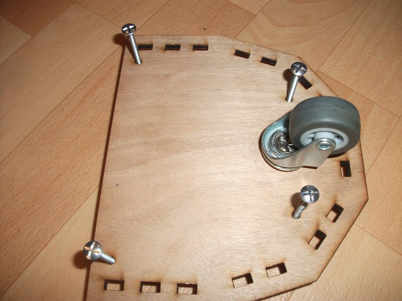
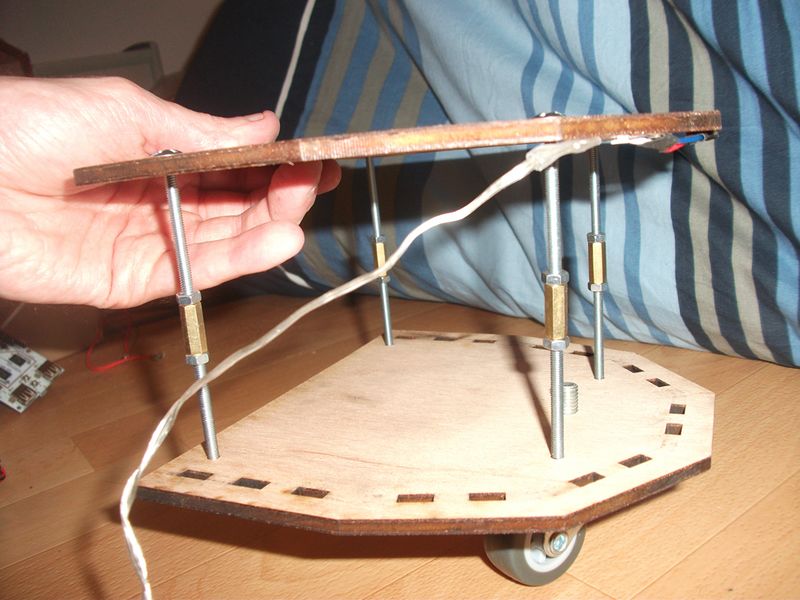
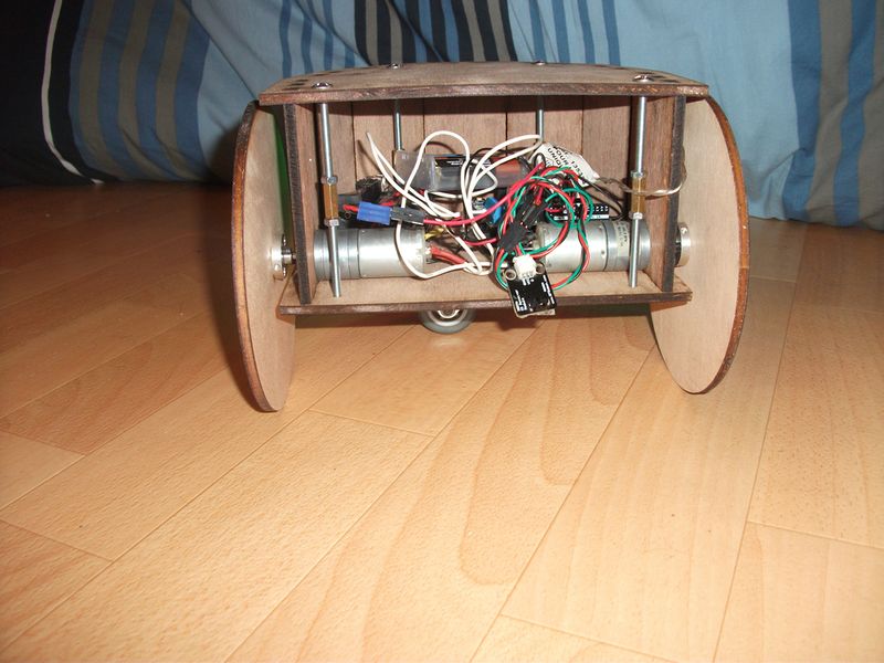
Inserte 4 tornillos M4 de 50 mm con tuercas y espaciadores, luego gire el conjunto para fijar el volante.
Étape 6 - Assemblage final
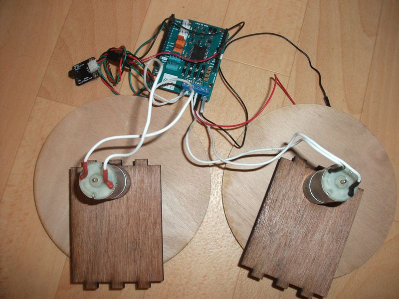
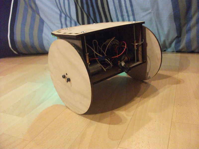
Assembler les arrondis ainsi que les cotés avec moteur sur l’illustration vu en étape 4.
Étape 9 - Évolutions envisagées
Prochaine évolution mettre un capteur ultrason pour détection et évitement d’obstacle et un suiveur de ligne.
Yes


 Français
 English
 Deutsch
 Español
 Italiano
 Português