| Ligne 142 : | Ligne 142 : | ||
4x Corner Plates | 4x Corner Plates | ||
| − | + | 44x T nuts | |
32x Washers | 32x Washers | ||
| Ligne 190 : | Ligne 190 : | ||
<nowiki>*</nowiki><u>A quick note about bracket orientation</u>. In image 2 you will see that the brackets are not the same on both sides. Here we have flipped one, so you can see the difference. One of the holes sits atop a raised lip, while the other is flush. The raised lip hole is ''closer'' to the brackets outside edge. The flush hole is ''farther'' from the outside edge. This matters for order of operations. When installing, you must install in the flush hole '''first''', and the hole with the raised lip '''second.''' If you do it in reverse the bolt will block access to the other hole. :) | <nowiki>*</nowiki><u>A quick note about bracket orientation</u>. In image 2 you will see that the brackets are not the same on both sides. Here we have flipped one, so you can see the difference. One of the holes sits atop a raised lip, while the other is flush. The raised lip hole is ''closer'' to the brackets outside edge. The flush hole is ''farther'' from the outside edge. This matters for order of operations. When installing, you must install in the flush hole '''first''', and the hole with the raised lip '''second.''' If you do it in reverse the bolt will block access to the other hole. :) | ||
| − | ==== Steps ==== | + | ====Steps==== |
| − | # Slide 4 nuts into the 520mm beam (2 in each rail). | + | #Slide 4 nuts into the 520mm beam (2 in each rail). |
| − | # Attach the 4 brackets loosely using M8x20mm bolts and washers. (image 3) | + | #Attach the 4 brackets loosely using M8x20mm bolts and washers. (image 3) |
| − | ## Note the orientation of the holes. All 4 bolts should go in flush holes, not raised lip holes. (figure 4) | + | ##Note the orientation of the holes. All 4 bolts should go in flush holes, not raised lip holes. (figure 4) |
| − | # With the table flipped on its end, position the 520mm beam in place, and slide 2 T-nuts in the rails to meet the brackets. Secure with same bolt washer combo. | + | #With the table flipped on its end, position the 520mm beam in place, and slide 2 T-nuts in the rails to meet the brackets. Secure with same M8x20 bolt washer combo. |
| − | # Repeat this process on the other side of the 520mm beam. | + | #Repeat this process on the other side of the 520mm beam. |
| − | # Repeat steps 1-4 on the opposite side.</translate> | + | #Repeat steps 1-4 on the opposite side of table.</translate> |
|Step_Picture_00=PP_Shredder_Pro_PXL_20210913_191021332.MP.jpg | |Step_Picture_00=PP_Shredder_Pro_PXL_20210913_191021332.MP.jpg | ||
|Step_Picture_01=PP_Shredder_Pro_PXL_20211012_220820636.jpg | |Step_Picture_01=PP_Shredder_Pro_PXL_20211012_220820636.jpg | ||
| Ligne 204 : | Ligne 204 : | ||
|Step_Picture_04=PP_Shredder_Pro_PXL_20210913_192421299.MP.jpg | |Step_Picture_04=PP_Shredder_Pro_PXL_20210913_192421299.MP.jpg | ||
|Step_Picture_05=PP_Shredder_Pro_PXL_20210913_192452373.MP.jpg | |Step_Picture_05=PP_Shredder_Pro_PXL_20210913_192452373.MP.jpg | ||
| + | }} | ||
| + | {{Tuto Step | ||
| + | |Step_Title=<translate>Table Construction - Center Struts</translate> | ||
| + | |Step_Content=<translate>====Tools==== | ||
| + | XX Socket Wrench | ||
| + | |||
| + | Screwdriver | ||
| + | ====Parts==== | ||
| + | 1x 4080*520mm | ||
| + | |||
| + | 1x 4080*455mm | ||
| + | |||
| + | 16 Brackets | ||
| + | |||
| + | |||
| + | 20x T nuts | ||
| + | |||
| + | 32x Washers | ||
| + | |||
| + | 32x M8x16mm Bolts | ||
| + | |||
| + | |||
| + | <u>*Construction note:</u> Until the very end, keep ALL of these bolt joints '''LOOSE.''' They will need to slide around to get everything in place. Once the location has been set, then you can tighten them down. | ||
| + | |||
| + | ====Steps==== | ||
| + | |||
| + | #Insert 4 T-nuts (2 in each rail) on one side of the 520mm 4080 (image1 ) | ||
| + | #For both beams, attach brackets (using the flush hole) at all 8 corners. (image 2) | ||
| + | #Arrange the beams so the 520mm beam is vertical, and the 455mm beam is horizontal, intersecting near the middle of the 520mm beam on the left hand side. | ||
| + | #''Loosely'' attach the horizontal beam to the vertical beam. | ||
| + | #Remember all those T-nuts we hid in the frame in [[step 4]]? Now we are going to connect this sub-assembly to them. | ||
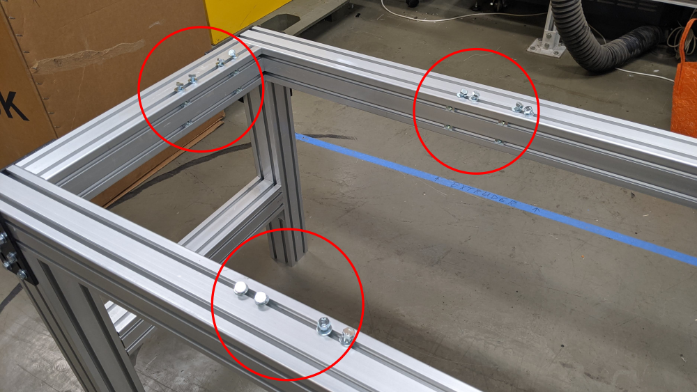
| + | #Place 4 bolts at each of the 3 locations designated in image 5. | ||
| + | #Drop the sub-assembly into the table frame, and loosely connect the brackets into the pre-loaded T-nuts | ||
| + | ##This is easier with 2 people. | ||
| + | ##You only need 1 bolt at each of the three locations to hold the weight of the sub-assembly. | ||
| + | ##After those first three bolts are in, you can easily go back and connect the others. | ||
| + | |||
| + | <br /></translate> | ||
| + | |Step_Picture_00=PP_Shredder_Pro_PXL_20211012_231904243.jpg | ||
| + | |Step_Picture_01=PP_Shredder_Pro_PXL_20211012_225744793.jpg | ||
| + | |Step_Picture_02=PP_Shredder_Pro_PXL_20211012_225829249.jpg | ||
| + | |Step_Picture_03=PP_Shredder_Pro_PXL_20211012_230032923.jpg | ||
| + | |Step_Picture_04=PP_Shredder_Pro_PXL_20211012_230121710.jpg | ||
| + | |Step_Picture_04_annotation={"version":"2.4.6","objects":[{"type":"image","version":"2.4.6","originX":"left","originY":"top","left":0,"top":0,"width":3840,"height":2160,"fill":"rgb(0,0,0)","stroke":null,"strokeWidth":0,"strokeDashArray":null,"strokeLineCap":"butt","strokeDashOffset":0,"strokeLineJoin":"miter","strokeMiterLimit":4,"scaleX":0.16,"scaleY":0.16,"angle":0,"flipX":false,"flipY":false,"opacity":1,"shadow":null,"visible":true,"clipTo":null,"backgroundColor":"","fillRule":"nonzero","paintFirst":"fill","globalCompositeOperation":"source-over","transformMatrix":null,"skewX":0,"skewY":0,"crossOrigin":"","cropX":0,"cropY":0,"src":"https://wikifab.org/images/7/78/PP_Shredder_Pro_PXL_20211012_230121710.jpg","filters":[]},{"type":"wfellipse","version":"2.4.6","originX":"center","originY":"center","left":173.03,"top":77.03,"width":107.28,"height":107.28,"fill":"rgba(255,0,0,0)","stroke":"#FF0000","strokeWidth":2,"strokeDashArray":null,"strokeLineCap":"butt","strokeDashOffset":0,"strokeLineJoin":"miter","strokeMiterLimit":4,"scaleX":1,"scaleY":1,"angle":0,"flipX":false,"flipY":false,"opacity":1,"shadow":null,"visible":true,"clipTo":null,"backgroundColor":"","fillRule":"nonzero","paintFirst":"fill","globalCompositeOperation":"source-over","transformMatrix":null,"skewX":0,"skewY":0,"rx":53.63985663273178,"ry":53.63985663273178},{"type":"wfellipse","version":"2.4.6","originX":"center","originY":"center","left":410.03,"top":96.03,"width":107.28,"height":107.28,"fill":"rgba(255,0,0,0)","stroke":"#FF0000","strokeWidth":2,"strokeDashArray":null,"strokeLineCap":"butt","strokeDashOffset":0,"strokeLineJoin":"miter","strokeMiterLimit":4,"scaleX":1,"scaleY":1,"angle":0,"flipX":false,"flipY":false,"opacity":1,"shadow":null,"visible":true,"clipTo":null,"backgroundColor":"","fillRule":"nonzero","paintFirst":"fill","globalCompositeOperation":"source-over","transformMatrix":null,"skewX":0,"skewY":0,"rx":53.63985663273178,"ry":53.63985663273178},{"type":"wfellipse","version":"2.4.6","originX":"center","originY":"center","left":247.63,"top":262.63,"width":130.09,"height":130.09,"fill":"rgba(255,0,0,0)","stroke":"#FF0000","strokeWidth":2,"strokeDashArray":null,"strokeLineCap":"butt","strokeDashOffset":0,"strokeLineJoin":"miter","strokeMiterLimit":4,"scaleX":1,"scaleY":1,"angle":0,"flipX":false,"flipY":false,"opacity":1,"shadow":null,"visible":true,"clipTo":null,"backgroundColor":"","fillRule":"nonzero","paintFirst":"fill","globalCompositeOperation":"source-over","transformMatrix":null,"skewX":0,"skewY":0,"rx":65.04529716570771,"ry":65.04529716570771}],"height":338,"width":600} | ||
| + | |Step_Picture_05=PP_Shredder_Pro_PXL_20211012_230832188.jpg | ||
}} | }} | ||
{{Notes | {{Notes | ||
Version du 13 octobre 2021 à 01:27
This tutorial documents the build process of Precious Plastic Pro Shredder, as supplied by Citizen Scientific for the North American context.

Difficulté
Difficile
Durée
5 jour(s)
Catégories
Machines & Outils, Recyclage & Upcycling, Robotique
Coût
5000 USD ($)
Matériaux
Outils
Étape 1 - Tools
Hammer
(punch) for knocking out leftover metal slugs
Files
Mallet
Socket wrench( 2x)
Tape measure
Screwdriver (directing the slide nuts)
Marker
Étape 2 - Table Parts
Parts Needed:
Aluminum Extrusion
| Profile | Length (mm) | Quantity |
|---|---|---|
| 8080 | 520 | 4 |
| 8080 | 600 | 4 |
| 8080 | 1200 | 2 |
| 4080 | 520 | 1 |
| 4080 | 455 | 1 |
| data-sheets-value="{"1":2,"2":"Corner Plates"}"
Étape 3 - Table Construction - LegsToolsXX Socket Wrench Screwdriver Parts4x 8080*600mm 2x 8080*1200mm 4x Side Plates 32x T nuts 32x Washers 32x M8x16mm Bolts Steps
You now have a staple shape. Repeat.
   
Étape 4 - Table Construction - Side JointsToolsXX Socket Wrench Screwdriver Parts2x 8080*520mm 4x Corner Plates 44x T nuts 32x Washers 32x M8x16mm Bolts Steps
You should now have a very solid table base! 

 
Étape 5 - Table Construction - Side BracesToolsXX Socket Wrench Screwdriver Parts2x 8080*520mm 8x Brackets 16x T nuts 16x Washers 16x M8x20mm Bolts
Steps
     
Étape 6 - Table Construction - Center StrutsToolsXX Socket Wrench Screwdriver Parts1x 4080*520mm 1x 4080*455mm 16 Brackets
32x Washers 32x M8x16mm Bolts
Steps
   

Draft |

 Français
 English
 Deutsch
 Español
 Italiano
 Português