
| Ligne 228 : | Ligne 228 : | ||
{{Tuto Step | {{Tuto Step | ||
|Step_Title=<translate>Barrel/Shaft/Bearings</translate> | |Step_Title=<translate>Barrel/Shaft/Bearings</translate> | ||
| − | |Step_Content=<translate></translate> | + | |Step_Content=<translate>==== Tools ==== |
| + | 1/2" Socket Wrench | ||
| + | |||
| + | adjustable wrench | ||
| + | |||
| + | ==== Parts ==== | ||
| + | Barrel | ||
| + | |||
| + | Extrusion Screw | ||
| + | |||
| + | 3x Bearings | ||
| + | |||
| + | 1x Bearing spacer | ||
| + | |||
| + | Flange | ||
| + | |||
| + | Bearing Housing | ||
| + | |||
| + | 8x M8x25 Bolts | ||
| + | |||
| + | 8x M8 washers | ||
| + | |||
| + | 8x M8 nuts | ||
| + | |||
| + | ==== Steps ==== | ||
| + | |||
| + | # Slide the bearings onto the screw shaft, followed by the bearing spacer. | ||
| + | # Slide the barrel over the screw. | ||
| + | # Slide the bearing housing over the bearings and flush with the barrel. | ||
| + | # Slide the flange over the shaft and flush with the bearing housing. | ||
| + | # Secure the bearing and flange in place with m8 bolts/washers/nuts. | ||
| + | # (see image 5 for a finished state, but ignore the other parts)</translate> | ||
| + | |Step_Picture_00=PP_Extruder_Pro_PXL_20211203_172746614.jpg | ||
| + | |Step_Picture_01=PP_Extruder_Pro_PXL_20211203_172803709.jpg | ||
| + | |Step_Picture_02=PP_Extruder_Pro_PXL_20211203_172829786.jpg | ||
| + | |Step_Picture_03=PP_Extruder_Pro_PXL_20211203_173209834.jpg | ||
| + | |Step_Picture_04=PP_Extruder_Pro_PXL_20211203_181341705.jpg | ||
| + | |Step_Picture_04_annotation={"version":"2.4.6","objects":[{"type":"image","version":"2.4.6","originX":"left","originY":"top","left":0,"top":0,"width":4032,"height":2268,"fill":"rgb(0,0,0)","stroke":null,"strokeWidth":0,"strokeDashArray":null,"strokeLineCap":"butt","strokeDashOffset":0,"strokeLineJoin":"miter","strokeMiterLimit":4,"scaleX":0.15,"scaleY":0.15,"angle":0,"flipX":false,"flipY":false,"opacity":1,"shadow":null,"visible":true,"clipTo":null,"backgroundColor":"","fillRule":"nonzero","paintFirst":"fill","globalCompositeOperation":"source-over","transformMatrix":null,"skewX":0,"skewY":0,"crossOrigin":"","cropX":0,"cropY":0,"src":"https://wikifab.org/images/3/3e/PP_Extruder_Pro_PXL_20211203_181341705.jpg","filters":[]},{"type":"wfellipse","version":"2.4.6","originX":"center","originY":"center","left":204.37,"top":119.37,"width":155.24,"height":155.24,"fill":"rgba(255,0,0,0)","stroke":"#FF0000","strokeWidth":2,"strokeDashArray":null,"strokeLineCap":"butt","strokeDashOffset":0,"strokeLineJoin":"miter","strokeMiterLimit":4,"scaleX":1,"scaleY":1,"angle":0,"flipX":false,"flipY":false,"opacity":1,"shadow":null,"visible":true,"clipTo":null,"backgroundColor":"","fillRule":"nonzero","paintFirst":"fill","globalCompositeOperation":"source-over","transformMatrix":null,"skewX":0,"skewY":0,"rx":77.62220353862689,"ry":77.62220353862689}],"height":338,"width":600} | ||
| + | }} | ||
| + | {{Tuto Step | ||
| + | |Step_Title=<translate>Coupling 1 and Heating elements</translate> | ||
| + | |Step_Content=<translate>==== Tools ==== | ||
| + | Mallet | ||
| + | |||
| + | Hex wrench (for heating element bolts, depends on manufacturer) | ||
| + | |||
| + | ==== Parts ==== | ||
| + | 20mm coupling | ||
| + | |||
| + | 1/4" Key(filed down) | ||
| + | |||
| + | 6x heating band elements | ||
| + | |||
| + | ==== Steps ==== | ||
| + | |||
| + | # Place the key into the keyway on the extruder shaft. | ||
| + | # Slide the coupling over the shaft/key until it is flush with the extruder shaft. It should '''not''' come into contact with the m8 Bolts on the flange. <br /> | ||
| + | # On the other end of the barrel, slide the heating elements into position. | ||
| + | ## Three should be within the barrel supports, and three should be past the support towards the extrusion end.</translate> | ||
| + | |Step_Picture_00=PP_Extruder_Pro_PXL_20211203_175222102.jpg | ||
| + | |Step_Picture_01=PP_Extruder_Pro_PXL_20211203_175227007.jpg | ||
| + | |Step_Picture_02=PP_Extruder_Pro_PXL_20211203_175238145.jpg | ||
| + | |Step_Picture_03=PP_Extruder_Pro_PXL_20211203_174837852.jpg | ||
}} | }} | ||
{{Notes | {{Notes | ||
Version du 3 décembre 2021 à 23:37
This tutorial documents the build process for the Precious Plastic Extruder Pro as supplied by Citizen Scientific Workshop out of Idaho, United States.

Difficulté
Moyen
Durée
2 jour(s)
Catégories
Machines & Outils, Recyclage & Upcycling
Coût
3000 USD ($)
Sommaire
- 1 Étape 1 - Table Build-Top deck 1
- 2 Étape 2 - Table Build- Top deck 2
- 3 Étape 3 - Table Build- Top deck 3
- 4 Étape 4 - Table Build - Side Legs 1
- 5 Étape 5 - Table Build - Side Legs 2
- 6 Étape 6 - Table Build - Tapping beams
- 7 Étape 7 - Barrel Support 1
- 8 Étape 8 - Barrel Support 2
- 9 Étape 9 - Barrel/Shaft/Bearings
- 10 Étape 10 - Coupling 1 and Heating elements
- 11 Commentaires
Matériaux
Outils
Étape 1 - Table Build-Top deck 1
Tools
1/2" Socket
Parts
2x 1000mm 4080 extrusion
4x 300mm 4040 extrusion
40x t-nuts
22x M8x20 bolts
22x M8 Washers
12x Corner Brackets
Steps
- Slide 6 t nuts into the top side of the 1000mm extrusion. (repeat for other beam)
- For the 300mm beams, 2 pairs of 2 will be identical, one "I" shaped, and one "C" shaped.
- For the C-shaped beam, Slide two t-nuts into one rail. Attach the corner brackets at the ends, ensuring the bracket is flush with the beams end. *Always use the side of the bracket with a flat face (non-lipped) first. This ensures you can get a tool onto the 2nd bolt without being blocked.
- For the I-Beams, repeat the same steps for the C-beam, but on both sides.
- Repeat so you have 2 I-beams and 2-C beams.
- *Optional* Add bolts to all remaining bracket holes and loosely attach t-nuts. (as seen in the right two beams in image 3)


Étape 2 - Table Build- Top deck 2
Tools
1/2" Socket Wrench
Parts
Assemblies from previous step
Steps
- If you have already attached the bolts/and t-nuts from the optional step - Slide beams into the upper channel (as seen in image 1) Otherwise, thread the nuts into the channel and attach LOOSELY with bolts.
- Repeat for the bottom rail.
- Secure the C beams in place with the socket wrench, but leave the I-beams LOOSE as they will need to be shifted later.


Étape 3 - Table Build- Top deck 3
Tools
1/2" Socket Wrench
Parts
Assembly from previous step
4x Steel Corner Brackets
32x M8x20 Bolts
32x M8 washers
32x t-nuts
Steps
- On the exterior corner of the 4080 extrusion, slide 3 t-nuts into each top/bottom rail.
- Secure corner plate to rale with accompanying 6 bolt/washer combos.
- Add 2 additional bolt/washer/t-nut combos to the 2 remaining vertical holes. Keep these very loose as we'll slide them into another assembly later.
- Repeat on all corners.


Étape 4 - Table Build - Side Legs 1
Tools
1/2" Socket Wrench
Parts
4x 800mm 4040 Aluminum extrusion
2x 300mm 4040 Aluminum extrusion
4x corner Brackets
8x M8x20 Bolts
8x M8 washers
8x t-nuts
Steps
- Slot 2 t-nuts into one rail of the 300mm extrusion
- Secure corner brackets on the rail, ensuring that the ends are flush with the beam.
- Slide a t-nut into a rail on the 800mm extrusion about 12in from the end.
- Secure one side of the short beam to the long beam.
- Repeat on the other side.
- Repeat steps 1-5 so you have 2 "H" assemblies.


Étape 5 - Table Build - Side Legs 2
Tools
1/2" Socket Wrench
Parts
2 "H" Assemblies from previous step
Top deck Assembly
Steps
- Shift the top deck assembly off your worksurface so that 2 corners are free hanging in space.
- Position an H assembly underneath the corners, aligning the pre-attached t-nuts to the external rail slots. This requires you to adjust the t-nuts so they are perfectly vertical.
- Slide the H assembly up until it is flush with the top deck and holding its weight.
- Once in place, tighten down the bolts
- Repeat on the other side.


Étape 6 - Table Build - Tapping beams
Tools
1/2" tap
Parts
Table assembly
Steps
- Tap the two central holes on the exterior of the 1000mm 4080 extrusion.
- Repeat on all 4 corners.


Étape 7 - Barrel Support 1
Tools
1/2" tap
1/2" socket wrench
3/4" socket wrench
Parts
2x 300mm Extrusion
2x Steel barrel brackets
4x corner brackets
4x 1/2"x1" hex bolts
4x 1/2" washers
4x M8x20 Bolts
4x M8 washers
4x t-nuts
Steps
- Tap both end holes in each 300mm beam.
- (check to make sure the 1/2 bolts fit through the large holes on the barrel brackets. If not, use a 1/2" drill bit to open the holes up)
- Slide 2 nuts into each beam. position these rails on the outside/facing away from each other (see image 6 for orientation)
- Secure the barrel brackets to the beams as seen in image 5.
- Secure corner brackets to slotted t-nuts so the open hole is facing down. Keep these loose as there final position will be determined later.


Étape 8 - Barrel Support 2
Tools
1/2" socket wrench
Parts
Barrel Support Assembly
Table
Barrel
4x M8x20 Bolts
4x M8 washers
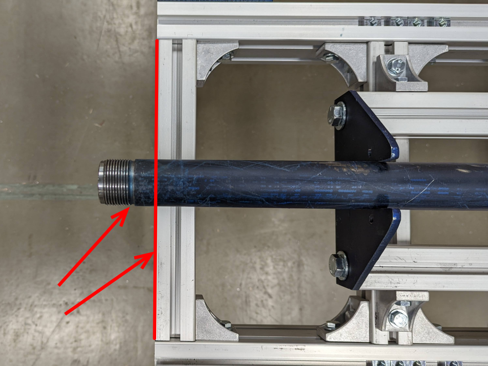
Steps
- Place the Barrel support assembly on the table so it that it crosses the two "I" assemblies.
- Loosely attach the assembly to the table with bolts/washers.
- Place the barrel into the support structure, aligning the flat notches on the barrel to the bracket.
- Slide the barrel towards the end of the table until the threads CLEAR the table face.
- Leave these connections loose as it will be moved into its final position later.
- Temporarily remove the barrel.

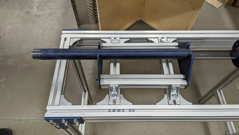
Étape 9 - Barrel/Shaft/Bearings
Tools
1/2" Socket Wrench
adjustable wrench
Parts
Barrel
Extrusion Screw
3x Bearings
1x Bearing spacer
Flange
Bearing Housing
8x M8x25 Bolts
8x M8 washers
8x M8 nuts
Steps
- Slide the bearings onto the screw shaft, followed by the bearing spacer.
- Slide the barrel over the screw.
- Slide the bearing housing over the bearings and flush with the barrel.
- Slide the flange over the shaft and flush with the bearing housing.
- Secure the bearing and flange in place with m8 bolts/washers/nuts.
- (see image 5 for a finished state, but ignore the other parts)


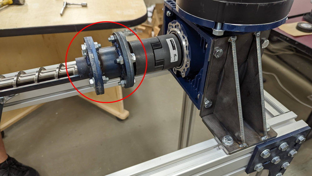
Étape 10 - Coupling 1 and Heating elements
Tools
Mallet
Hex wrench (for heating element bolts, depends on manufacturer)
Parts
20mm coupling
1/4" Key(filed down)
6x heating band elements
Steps
- Place the key into the keyway on the extruder shaft.
- Slide the coupling over the shaft/key until it is flush with the extruder shaft. It should not come into contact with the m8 Bolts on the flange.
- On the other end of the barrel, slide the heating elements into position.
- Three should be within the barrel supports, and three should be past the support towards the extrusion end.


Draft
 Français
 English
 Deutsch
 Español
 Italiano
 Português