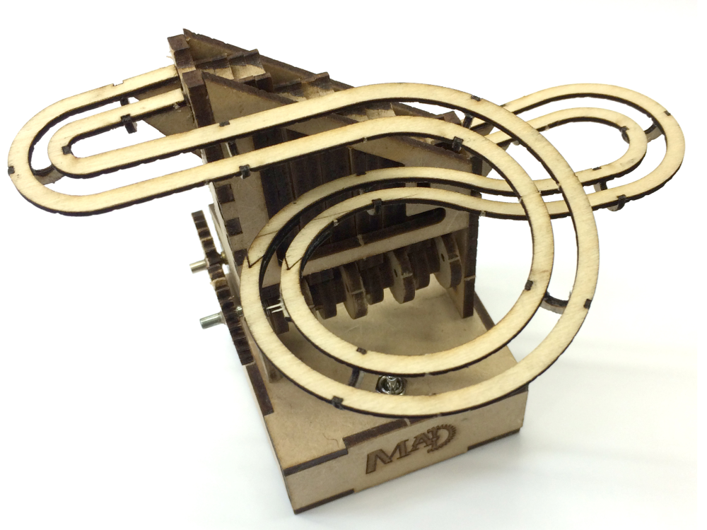
Build instruction the Marble Machine No.1 (Motor Version). Kit can be purchased from www.madfactory.co.uk

Difficulté
Moyen
Durée
1 heure(s)
Catégories
Art, Machines & Outils, Jeux & Loisirs
Coût
19.99 GBP (£)
Sommaire
- 1 Introduction
- 2 Video d'introduction
- 3 Étape 1 -
- 4 Étape 2 - Camshaft Assembly
- 5 Étape 3 - Base Assembly
- 6 Étape 4 - Frame Assembly 1
- 7 Étape 5 - Frame Assembly 2
- 8 Étape 6 - Frame Assembly 3
- 9 Étape 7 - Track Supports
- 10 Étape 8 - “Steps” Assembly 1
- 11 Étape 9 - “Steps” Assembly 2
- 12 Étape 10 - “Steps” Assembly 3
- 13 Étape 11 - Track Assembly
- 14 Étape 12 - Attach track to the frame 1
- 15 Étape 13 - Attach track to the frame 2
- 16 Étape 14 - Attach gears & motor
- 17 Étape 15 - Wiring
- 18 Étape 16 - Fine Tuning
- 19 Étape 17 - Track Supports
- 20 Étape 18 - “Steps” Assembly 1
- 21 Étape 19 - “Steps” Assembly 2
- 22 Étape 20 - “Steps” Assembly 3
- 23 Étape 21 - Track Assembly
- 24 Étape 22 - Attach track to the frame 1
- 25 Étape 23 - Attach track to the frame 2
- 26 Étape 24 - Attach gears & motor
- 27 Étape 25 - Wiring
- 28 Étape 26 - Fine Tuning
- 29 Commentaires
Introduction
Please note:
It is recommended that you apply varnish or sealer to the finished marble machine, especially if you live in areas with high humidity. Polyurethane varnish is a good choice.
If you manage to drop some of the balls on the floor (inevitable!) then DO NOT be tempted to pick them up with a magnet. This can cause the balls to become magnetised and they will then stick together which will impair the operation of the marble machine.
Before you start assembly it is a good idea to study the pictures in these instruction so you know how it goes together. You can dry assemble the lifter initially.
This kit contains small parts and is not suitable for small childrenYoutube
Matériaux
Outils
Wood glue (PVA) and/or Cyanoacrylate (CA) glue
Clamps, clothes pegs, weights or rubber bands
Sandpaper
25-40w Soldering iron
Solder
Étape 1 -
Étape 2 - Camshaft Assembly
First you must sand the pips off the cam wheels. Place them on the 3mm axle and use one of the 2mm axles to hold them aligned so you can sand them pips off in one go.
Use the supplied jigs and 2mm rods to ensure the cams are properly aligned on the 3mm axle. The axle should protrude 2mm from the jig at one end as shown below. Layer the cams and spacers with the application of wood glue between each part. Use rubber bands to hold the assembly together while the glue sets and make sure the jigs is on a level surface.
Étape 3 - Base Assembly
The parts can be glued together in one go and the parts held in place with rubber bands The bottom should not be glued but can be used to hold parts aligned while the glue dries. The bottom is left loose for access to switch and batteries.
If you don't want the text to be visible, simply turn the part so it face inwards. When viewed from the front the holes for the motor mount (circled in red) should face left as shown in the picture below.
Étape 4 - Frame Assembly 1
Use glue sparingly – you don't want a lot of glue to go inside the frame as this can interfere with the movement of the steps. Any excess glue can be wiped off with a damp rag.
- Glue the motor mount parts together and insert them into the tall upright. Insert them into to base to hold them aligned but do not glue them to the base at this point. Use the bottom of the base to check that the upright is square to the base.
Étape 5 - Frame Assembly 2
Place 2 washers on each end of the camshaft and slide it in place between the frame ends. The long free end of the camshaft must face left.
Étape 6 - Frame Assembly 3
- Now glue the front and rear frame pieces in place. The tabs/slot differ in size so you cannot attach them the wrong way round.
- Next glue the uprights to the base. Hold the frame pieces together with rubber bands while the glue sets.
Étape 7 - Track Supports
Glue the top, front and bottom track supports to the frame. IMPORTANT the two at the top slope downwards and the two at the bottom slope upwards (see pictures)
Étape 8 - “Steps” Assembly 1
Each step consists of two parts. Apply wood glue sparingly and assemble the stack using the 2mm rods to ensure good alignment. Be careful you don't get glue on the surfaces that shouldn't be joined! you can leave a slight gap between each step to prevent this.
Étape 9 - “Steps” Assembly 2
Clamp the parts or wrap with rubber bands and allow the glue to dry. One part is marked. This is so you can identify front from back when you sand the slope into the steps.
Once the steps are dry, sand the sides and chamfer the corners slightly. This prevents binding. You may also need to sand the faces that rub together to ensure they do not bind. Use a fine grade sandpaper. The smoother the steps are the better and it is recommended that you apply a light coat of varnish or MDF sealer and rub them down with fine sandpaper when dry. This makes the surfaces smoother.
Now it's time to tackle the top of the steps. These need to be at an angle so the balls easily roll from step to step. Wrap sandpaper around a dowel or pen 5-7mm in diameter and sand the top of the steps at approximately a 5-7 degree angle.
If you have a Dremel type tool with a small diameter sanding drum use that but be careful not to remove too much material from a step so it cannot reach above the next step up. Place the steps in the frame from time to time and check that they match up. When a lower step is in its top position it should still be a bit taller than the next step up so the ball will roll from step to step. If you accidentally sand off too much then a piece of scrap plywood can be glued to the bottom of the step and you can then proceed to sand the top until it aligns with the other steps.
Étape 10 - “Steps” Assembly 3
Next place the steps into the frame making sure the angle on each step angles down away from the smaller previous step. if the steps are too loose in the frame glue a spacer step to one the steps, repeating as necessary to close the gap in the frame make sure the steps are loose enough to move up and down.
Étape 11 - Track Assembly
Do not remove the tracks from the retaining sheet at this stage. They should be left in place until the track joiners are glued in place. However the piece between the tracks should be removed before the track spreaders are fitted. Use a sharp knife to cut the retaining tabs.
The track spreaders should be mounted on the opposite side of the side with the “O” engraved so put the “O” underneath when you glue the spreaders on. Double check orientation before assembling the track so you don't end up with a track the won't fit on the front of the lifter!
Remove the track spreaders from the sheet. Glue them to the tracks with wood glue. A fast way to do this is to put a good sized blob of glue on a scrap piece of paper and then dip the spreaders in the glue before mounting them in the cut outs in the track.
Étape 12 - Attach track to the frame 1
The track should be glued to the frame in two stages. If you use CA glue you can simply hold the parts in place while the glue sets. If using wood glue you will need a scrap of MDF and some rubber bands to hold the track in place while the glue dries. Start by glueing the track to the lower track support and the side support. Once dry you can glue the track to the upper track support.
Étape 13 - Attach track to the frame 2
When the track is glued in place, sand the tops of the uprights at an angle so the balls run smoothly off the steps and onto the steps.
Étape 14 - Attach gears & motor
Place a washer on the protruding crankshaft. Fit the gear and doubler onto the shaft. A tiny drop of CA glue between the gear and doubler will suffice to keep the gear in place on the shaft.
Push the gear-motor into the frame so it sits flush with the frame. Glue gear and doubler together and slide onto the motor axle.
Étape 15 - Wiring
The circuit should be as per the picture below. Solder the leads to the switch but do not solder the leads onto the motor until it is mounted in the frame. The polarity does not matter – the machine works regardless of the motors rotation.
Use a 25-40W soldering iron with a small tip and flux cored electronics solder. Keep that big old iron used for plumbing far away from this kit. It will melt the motor backplate and ruin it.
Place the completed marble machine on a level surface, drop 6-8 balls on the track, hit the switch and set the machine in motion.
Étape 16 - Fine Tuning
If the steps get stuck on a step or at the bottome of the track you may need to sand each part carefully to fix this. Be aware any blobs of glue/paint on the track or steps will affect the how the balls move.
Étape 17 - Track Supports
Glue the top, front and bottom track supports to the frame. IMPORTANT the two at the top slope downwards and the two at the bottom slope upwards (see pictures)
Étape 18 - “Steps” Assembly 1
Each step consists of two parts. Apply wood glue sparingly and assemble the stack using the 2mm rods to ensure good alignment. Be careful you don't get glue on the surfaces that shouldn't be joined! you can leave a slight gap between each step to prevent this.
Étape 19 - “Steps” Assembly 2
Clamp the parts or wrap with rubber bands and allow the glue to dry. One part is marked. This is so you can identify front from back when you sand the slope into the steps.
Once the steps are dry, sand the sides and chamfer the corners slightly. This prevents binding. You may also need to sand the faces that rub together to ensure they do not bind. Use a fine grade sandpaper. The smoother the steps are the better and it is recommended that you apply a light coat of varnish or MDF sealer and rub them down with fine sandpaper when dry. This makes the surfaces smoother.
Now it's time to tackle the top of the steps. These need to be at an angle so the balls easily roll from step to step. Wrap sandpaper around a dowel or pen 5-7mm in diameter and sand the top of the steps at approximately a 5-7 degree angle.
If you have a Dremel type tool with a small diameter sanding drum use that but be careful not to remove too much material from a step so it cannot reach above the next step up. Place the steps in the frame from time to time and check that they match up. When a lower step is in its top position it should still be a bit taller than the next step up so the ball will roll from step to step. If you accidentally sand off too much then a piece of scrap plywood can be glued to the bottom of the step and you can then proceed to sand the top until it aligns with the other steps.
Étape 20 - “Steps” Assembly 3
Next place the steps into the frame making sure the angle on each step angles down away from the smaller previous step. if the steps are too loose in the frame glue a spacer step to one the steps, repeating as necessary to close the gap in the frame make sure the steps are loose enough to move up and down.
Étape 21 - Track Assembly
Do not remove the tracks from the retaining sheet at this stage. They should be left in place until the track joiners are glued in place. However the piece between the tracks should be removed before the track spreaders are fitted. Use a sharp knife to cut the retaining tabs.
The track spreaders should be mounted on the opposite side of the side with the “O” engraved so put the “O” underneath when you glue the spreaders on. Double check orientation before assembling the track so you don't end up with a track the won't fit on the front of the lifter!
Remove the track spreaders from the sheet. Glue them to the tracks with wood glue. A fast way to do this is to put a good sized blob of glue on a scrap piece of paper and then dip the spreaders in the glue before mounting them in the cut outs in the track.
Étape 22 - Attach track to the frame 1
The track should be glued to the frame in two stages. If you use CA glue you can simply hold the parts in place while the glue sets. If using wood glue you will need a scrap of MDF and some rubber bands to hold the track in place while the glue dries. Start by glueing the track to the lower track support and the side support. Once dry you can glue the track to the upper track support.
Étape 23 - Attach track to the frame 2
When the track is glued in place, sand the tops of the uprights at an angle so the balls run smoothly off the steps and onto the steps.
Étape 24 - Attach gears & motor
Place a washer on the protruding crankshaft. Fit the gear and doubler onto the shaft. A tiny drop of CA glue between the gear and doubler will suffice to keep the gear in place on the shaft.
Push the gear-motor into the frame so it sits flush with the frame. Glue gear and doubler together and slide onto the motor axle.
Étape 25 - Wiring
The circuit should be as per the picture below. Solder the leads to the switch but do not solder the leads onto the motor until it is mounted in the frame. The polarity does not matter – the machine works regardless of the motors rotation.
Use a 25-40W soldering iron with a small tip and flux cored electronics solder. Keep that big old iron used for plumbing far away from this kit. It will melt the motor backplate and ruin it.
Place the completed marble machine on a level surface, drop 6-8 balls on the track, hit the switch and set the machine in motion.
Étape 26 - Fine Tuning
If the steps get stuck on a step or at the bottome of the track you may need to sand each part carefully to fix this. Be aware any blobs of glue/paint on the track or steps will affect the how the balls move.
Draft
 Français
 English
 Deutsch
 Español
 Italiano
 Português