| Ligne 34 : | Ligne 34 : | ||
https://github.com/arendst/Tasmota/issues/7385 | https://github.com/arendst/Tasmota/issues/7385 | ||
| − | <br /></translate> | + | |
| + | The ESP is used with Tasmota installed and communicates with the IC over serial.<br /></translate> | ||
|Step_Picture_00=Is_it_possible_to_replace_the_WR3_module_with_an_ESP-12_module_1_WiFi_module.jpg | |Step_Picture_00=Is_it_possible_to_replace_the_WR3_module_with_an_ESP-12_module_1_WiFi_module.jpg | ||
}} | }} | ||
Version actuelle datée du 14 octobre 2021 à 23:03
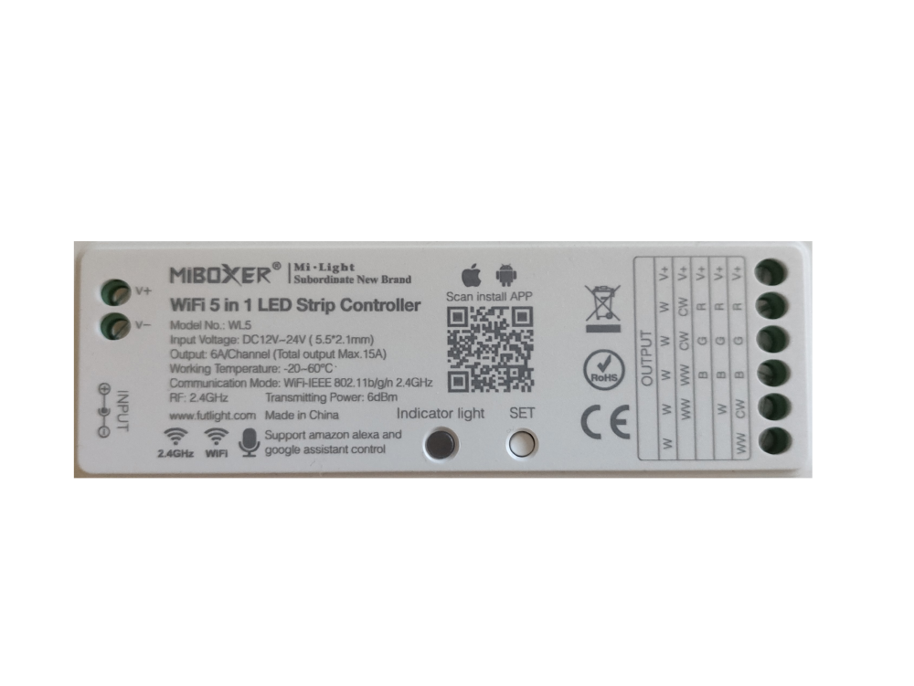
In this Documentation I am showing what I was able to find out about the MiBoxer WL5 5 in 1 WiFi RGB+CCT Controller.

Difficulté
Moyen
Durée
20 minute(s)
Catégories
Électronique
Coût
15 EUR (€)
Introduction
I ordered a RGB+CCT controller online and to my surprise the device came with a new Tuya WiFi module instead of an ESP module.
Now I am trying to swap the WR3 Tuya WiFi module with an ESP-12f module.
Matériaux
Outils
Étape 1 - The PCB on which the Tuya WR3 module is soldered on.
I desoldered the WR3 module to check the connections with my meter and also used a lamp to expose the traces.
I checked the conenctions and it seems that only RX, TX , VCC, GND and EN are connected.
I found this thread, but still do not know how to connect it properly.
I will figure out the software side.
https://github.com/arendst/Tasmota/issues/7385
The ESP is used with Tasmota installed and communicates with the IC over serial.

Étape 2 - The Top and bottom side of the whole PCB.
This shows the top and bottom side

Published
 Français
 English
 Deutsch
 Español
 Italiano
 Português