(Page créée avec « {{ {{tntn|Tuto Details}} |SourceLanguage=none |Language=en |IsTranslation=0 |Main_Picture=IoT_with_ESP32_board_connectedhouse_intro.PNG |Licences=Attribution (CC BY) |Desc... ») |
|||
| Ligne 1 : | Ligne 1 : | ||
{{ {{tntn|Tuto Details}} | {{ {{tntn|Tuto Details}} | ||
| − | |||
| − | |||
| − | |||
|Main_Picture=IoT_with_ESP32_board_connectedhouse_intro.PNG | |Main_Picture=IoT_with_ESP32_board_connectedhouse_intro.PNG | ||
|Licences=Attribution (CC BY) | |Licences=Attribution (CC BY) | ||
| Ligne 14 : | Ligne 11 : | ||
|Currency=EUR (€) | |Currency=EUR (€) | ||
|Tags=ESP32, internet of things, adafruit.io | |Tags=ESP32, internet of things, adafruit.io | ||
| + | |SourceLanguage=none | ||
| + | |Language=en | ||
| + | |IsTranslation=0 | ||
}} | }} | ||
{{ {{tntn|Introduction}} | {{ {{tntn|Introduction}} | ||
| Ligne 66 : | Ligne 66 : | ||
|Step_Title=Wiring the photoresistor to the ESP32 | |Step_Title=Wiring the photoresistor to the ESP32 | ||
|Step_Content=The shorter leg of the photoresistor is connected to 3V on the ESP32. The other leg is connected to pin VP (or 36) and at the same time to a 1kohm resistor, which in turn is connected to GND on the ESP32. | |Step_Content=The shorter leg of the photoresistor is connected to 3V on the ESP32. The other leg is connected to pin VP (or 36) and at the same time to a 1kohm resistor, which in turn is connected to GND on the ESP32. | ||
| + | |Step_Picture_00=IoT_with_ESP32_board_wiring1.PNG | ||
| + | |Step_Picture_01=IoT_with_ESP32_board_wiring2.PNG | ||
| + | |Step_Picture_02=IoT_with_ESP32_board_wiring3.PNG | ||
}} | }} | ||
{{ {{tntn|Tuto Step}} | {{ {{tntn|Tuto Step}} | ||
| Ligne 74 : | Ligne 77 : | ||
The “User Name” and “Key” are available on your adafruit.io account (see image below) | The “User Name” and “Key” are available on your adafruit.io account (see image below) | ||
| + | |Step_Picture_00=IoT_with_ESP32_board_tuniot.PNG | ||
| + | |Step_Picture_01=IoT_with_ESP32_board_aio_key.PNG | ||
}} | }} | ||
{{ {{tntn|Tuto Step}} | {{ {{tntn|Tuto Step}} | ||
|Step_Title=Install Adafruit_MQTT.h and Adafruit_MQTT_Client.h libraries on Arduino IDE | |Step_Title=Install Adafruit_MQTT.h and Adafruit_MQTT_Client.h libraries on Arduino IDE | ||
|Step_Content=Sketch > Include Library > Manage Libraries… | |Step_Content=Sketch > Include Library > Manage Libraries… | ||
| + | |Step_Picture_00=IoT_with_ESP32_board_libes.PNG | ||
}} | }} | ||
{{ {{tntn|Tuto Step}} | {{ {{tntn|Tuto Step}} | ||
| Ligne 88 : | Ligne 94 : | ||
It means that your ESP32 is connected to the internet, and that it’s sending the value recorded by the photoresistor on-line, on adafruit.io | It means that your ESP32 is connected to the internet, and that it’s sending the value recorded by the photoresistor on-line, on adafruit.io | ||
| + | |Step_Picture_00=IoT_with_ESP32_board_program_arduino.PNG | ||
| + | |Step_Picture_01=IoT_with_ESP32_board_serialmon.PNG | ||
| + | |Step_Picture_02=IoT_with_ESP32_board_connectedhouse_intro.PNG | ||
}} | }} | ||
{{ {{tntn|Notes}} | {{ {{tntn|Notes}} | ||
Version du 20 août 2018 à 15:24
Sommaire
- 1 Introduction
- 2 Étape 1 - Set up an account on adafruit.io
- 3 Étape 2 - Install Arduino IDE
- 4 Étape 3 - Prepare the ESP32 board on your computer
- 5 Étape 4 - Check that the board is correctly configured
- 6 Étape 5 - Wiring the photoresistor to the ESP32
- 7 Étape 6 - Programming on tuniot
- 8 Étape 7 - Install Adafruit_MQTT.h and Adafruit_MQTT_Client.h libraries on Arduino IDE
- 9 Étape 8 - Programming on Arduino IDE
- 10 Commentaires
Introduction
Matériaux
1 x ESP32 board + Micro USB cable
1 x light sensor
About 5 jumper wires
1 x 1Kohm resistor
Outils
Computer with internet connection and Arduino IDE installed
Étape 1 - Set up an account on adafruit.io
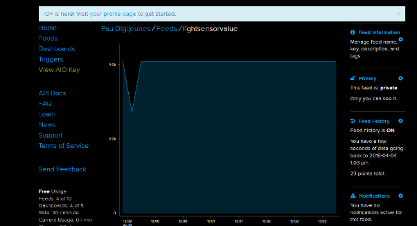
Once you have set up an account on adafruit.io, go ahead creating a new Feed. Creat a new feed and name it, for example "lightsensorvalue".
Étape 2 - Install Arduino IDE
You can download the software here.
Étape 3 - Prepare the ESP32 board on your computer
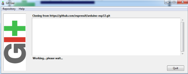
Follow the instructions provided on github for your OS.
For Windows
If you have troubles following the instructions for windows, you may find some help below
To find the Sketch directory, click File > Preferences, on arduino IDE.
The process of cloning existing repository may take a while...
Étape 4 - Check that the board is correctly configured
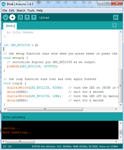
Launch Arduino IDE
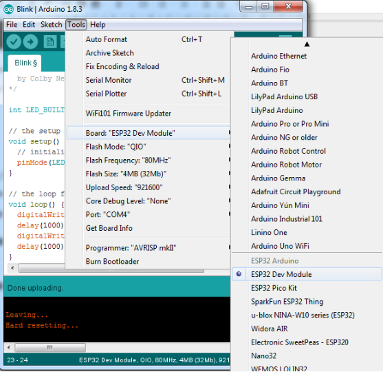
Go to Tools > Board and select “ESP32 Dev Module”.
Fetch the Blink example on File > Examples > Basics > Blink.
Upload the code by clicking on the arrow pointing to the right, on the top left of the arduino IDE window.
Étape 5 - Wiring the photoresistor to the ESP32
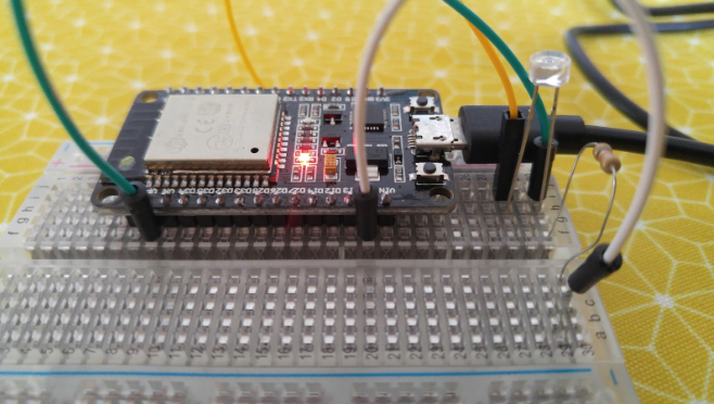
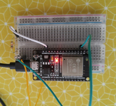
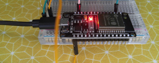
The shorter leg of the photoresistor is connected to 3V on the ESP32. The other leg is connected to pin VP (or 36) and at the same time to a 1kohm resistor, which in turn is connected to GND on the ESP32.
Étape 6 - Programming on tuniot
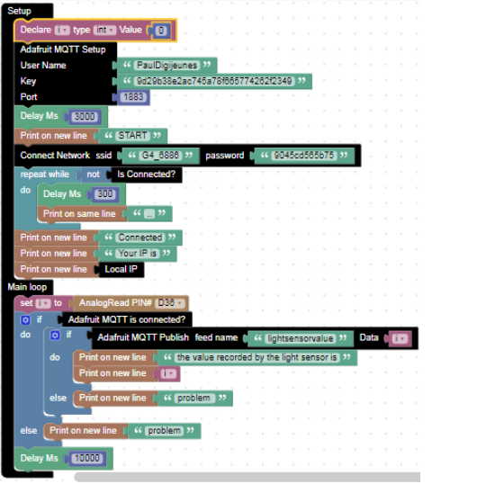
On tuniot, we will use the blocks available to create a code for the ESP32.
complete the fields “ssid” and “password” with the name of your wi-fi connection and its password respectively.
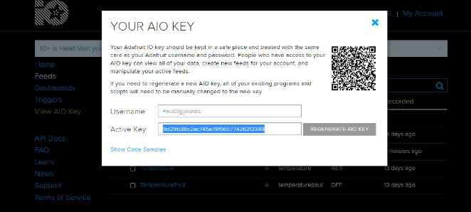
The “User Name” and “Key” are available on your adafruit.io account (see image below)
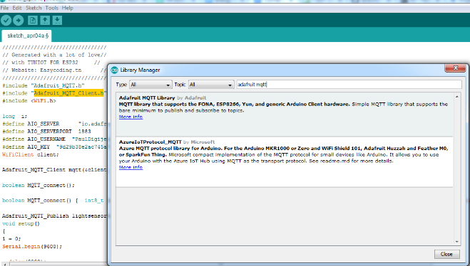
Étape 7 - Install Adafruit_MQTT.h and Adafruit_MQTT_Client.h libraries on Arduino IDE
Sketch > Include Library > Manage Libraries…
Étape 8 - Programming on Arduino IDE
To upload the code on Arduino IDE, click on the “copy arduino code into clipboard” button
then paste the code onto Arduino IDE, and upload it to the ESP32.
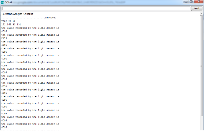
if you click on Serial Monitor (top right of the Arduino IDE screen), you should be able to see the value that is being recorded by the light sensor (see image below).
It means that your ESP32 is connected to the internet, and that it’s sending the value recorded by the photoresistor on-line, on adafruit.io
Draft

 Français
 English
 Deutsch
 Español
 Italiano
 Português