Sommaire
- 1 Introduction
- 2 Étape 1 - Cut the plywood
- 3 Étape 2 - Cut sides to fit together
- 4 Étape 3 - Cut and weld the LED strip
- 5 Étape 4 - Assemble and glue the box
- 6 Étape 5 - Glue the separation walls
- 7 Étape 6 - Glue a support board for the electronic board
- 8 Étape 7 - Fix the Arduino board
- 9 Étape 8 - Weld components
- 10 Étape 9 - Load the program
- 11 Étape 10 - Add the plexi windows
- 12 Étape 11 - It's done
- 13 Commentaires
Introduction
This tutorial is inspired from the creation of Philippe Chrétien. Here is his website : http://geekoclock.com/
This version is base on an Arduino UNO board.
This project use a addressable RGB LEDs strip. It enable to control color and intensity of each LED individually, using only one control pin on the Arduino.
Matériaux
- plywood 5mm thick
- plexi
- Arduino UNO board
- Real Time clock module RTC DS1307
- addressable RGB LED strip
- 4 push buttons
- power supply for arduino
- supply connector
- electric wires
Warning : check that your RGB LED strip is addressable. The strip I used has the following reference : WS2812B
Outils
- scie
- fer à souder
- perceuse
- cutter
- lime à bois
- colle à bois
Étape 1 - Cut the plywood
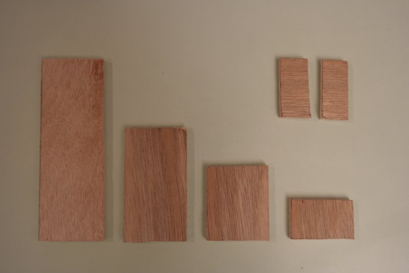
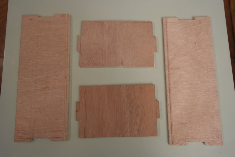
Cut 4 plywood board for outside walls, 2 others for bottom and double-bottom, and 4 littles more for inside walls to split squares. Dimensions are the following :
For outside walls :
- 2 boards 85mm * 221mm
- 2 boards 85mm * 138mm
for bottom and double-bottom :
- 2 boards 128mm * 211mm
for inside walls:
- 1 board 50mm * 128mm
- 1 board 50mm * 78mm
- 1 board 50mm * 50mm
- 1 board 50mm * 26mm
Étape 2 - Cut sides to fit together
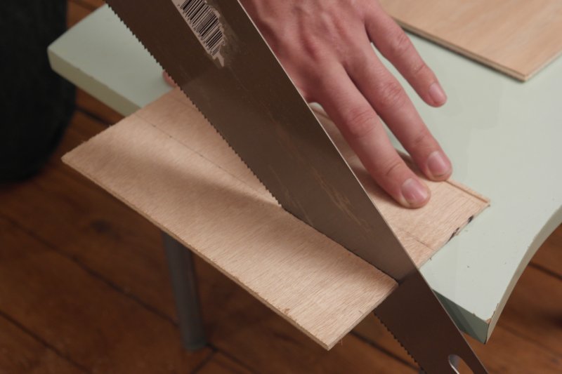
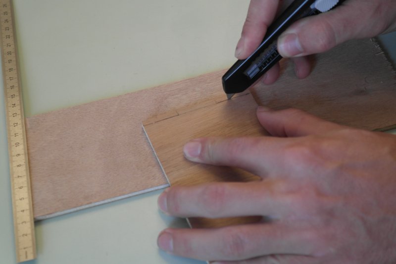
Cut 4mm slots to fit together the four sides.
Use a wood file for the finishing.
Étape 3 - Cut and weld the LED strip
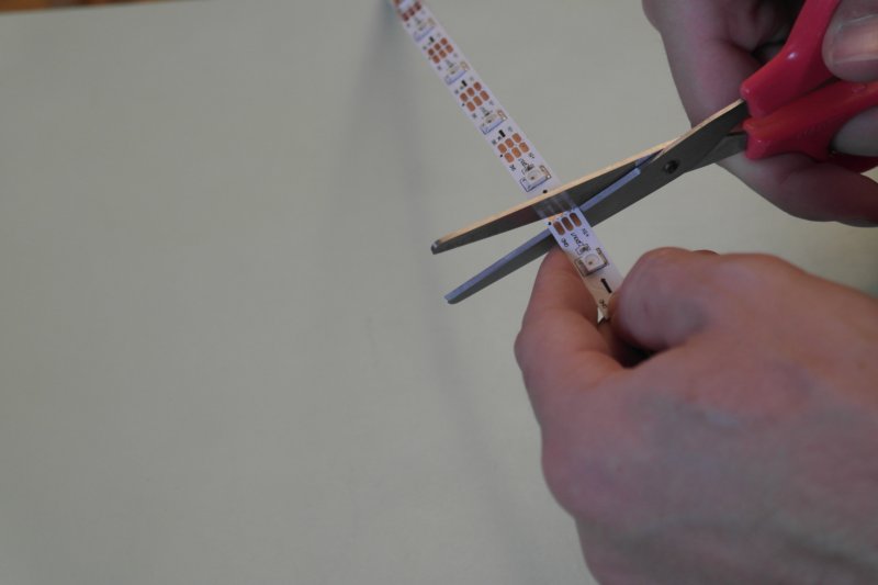
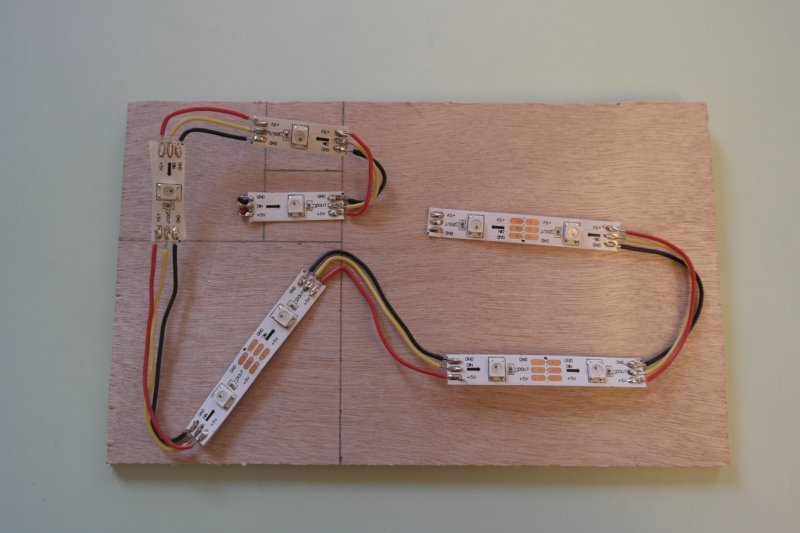
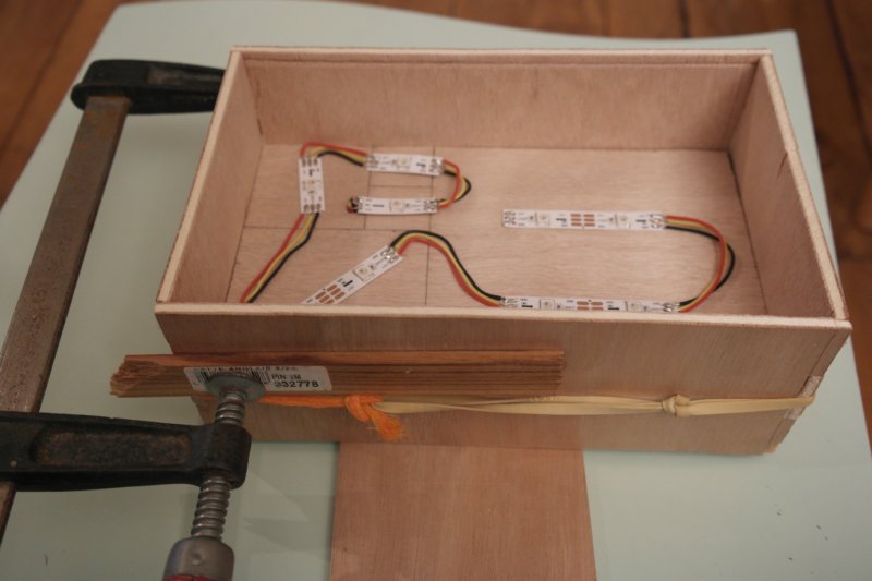
Cut the LED strip into 3 strips of 1 LED and 3 strips of 2 LEDS.
Weld with small wires with good length, to place them into squares, as shown on the picture.
Then glue the strip on the wood board of the double-bottom.
Put a hole to pass wires to the other side of the double-bottom.
Étape 4 - Assemble and glue the box
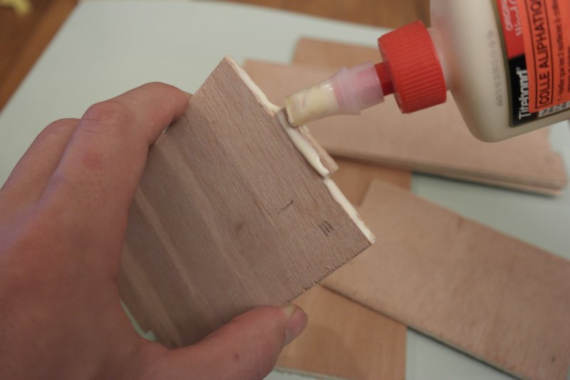
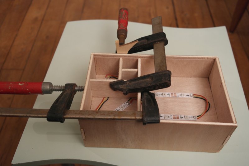
Glue the 4 sides with the double-bottom, positioning it at 5cm from the front.
Wait until the glue dries. (20 min minimum)
Étape 6 - Glue a support board for the electronic board
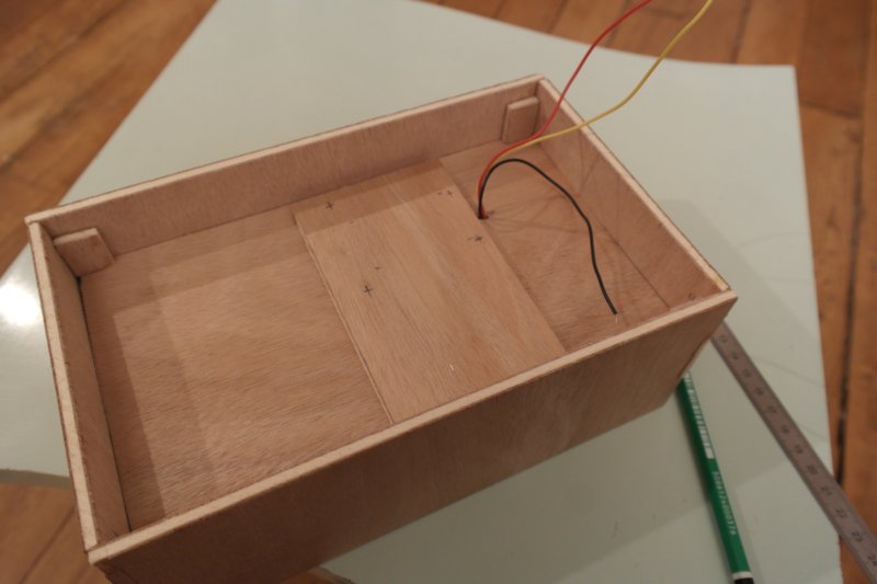
Prepare now the other side of the double-bottom :
To fix the electronic board, and avoid screw exceed from the wood board, we add wood thickness where we want to place the electronic board.
Étape 7 - Fix the Arduino board
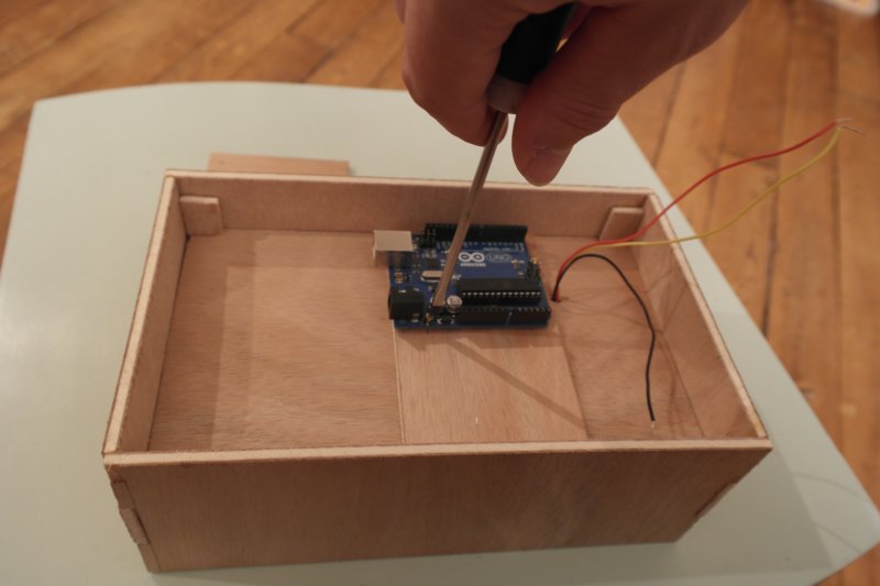
Put small pre-holes for the srew, then fix the arduino board on the double-bottom.
Étape 8 - Weld components
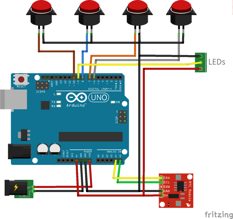
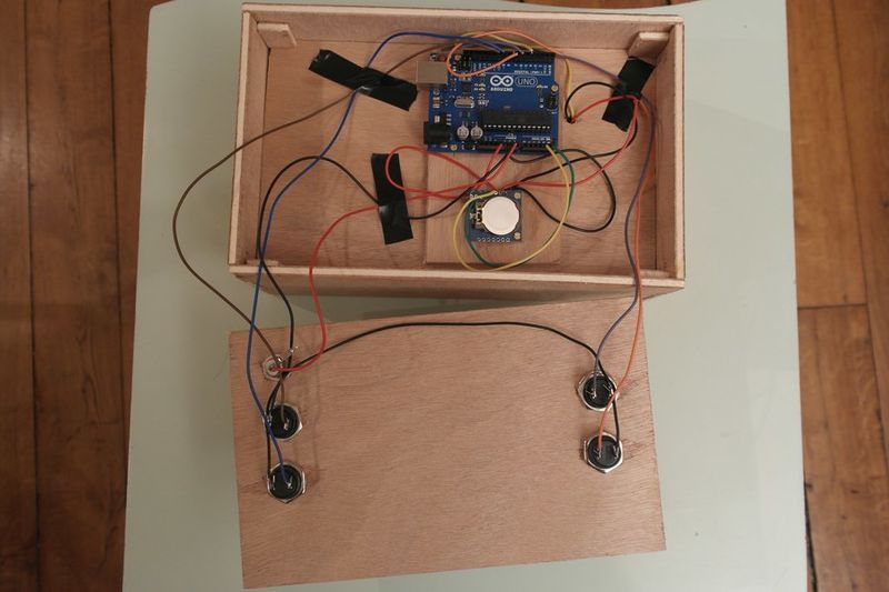
Follow the given scheme to weld wires. I tape wires in order that they stay in place. Only wire on the Arduino board aren't weld.
Étape 9 - Load the program
Download Arduino IDE : https://www.arduino.cc/en/Main/Software
Install the NeoPixel Library, available here : https://github.com/adafruit/Adafruit_NeoPixel
After download it, rename the directory to 'Adafruit_NeoPixel' and place it into the directory 'librairie' into the directory of your IDE installation.
The Arduino program of the clock is available on Github : https://github.com/pierreboutet/fibonacciClock
Download it, and open it with the Arduino IDE
Plug the arduino board with the usb wire, et upload the program from the IDE.
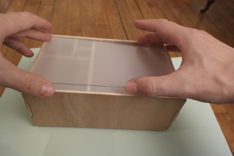
Étape 10 - Add the plexi windows
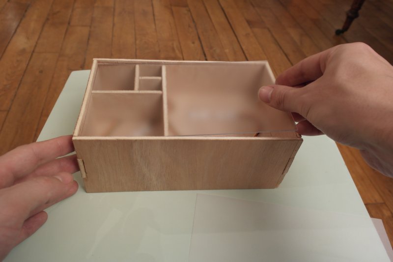
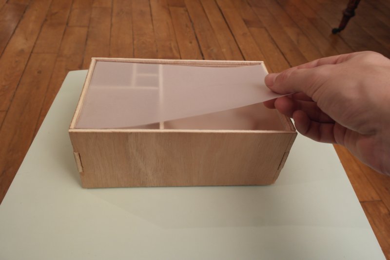
To get good opacity, i place a tracing-paper between two transparent plexi.
Thus, it is enough opaque to transmit light homogeneously. And LEDs aren't directly visibles.
Idealy one unique white plexy board non opaque would fit, but I didn't have any.
Étape 11 - It's done
You can plug your clock, and learn how to read time. :)
How to read time ?
Squares have values of the Fibonacci sequence :
1 1 2 3 5
Red squares count for hours,
Green squares count for minutes,
and blue squares count for both hours and minutes.
We get hours and minute by addition of the matching squares values. For minutes the values must be multiplied by 5, because the clock count by 5 minutes steps.
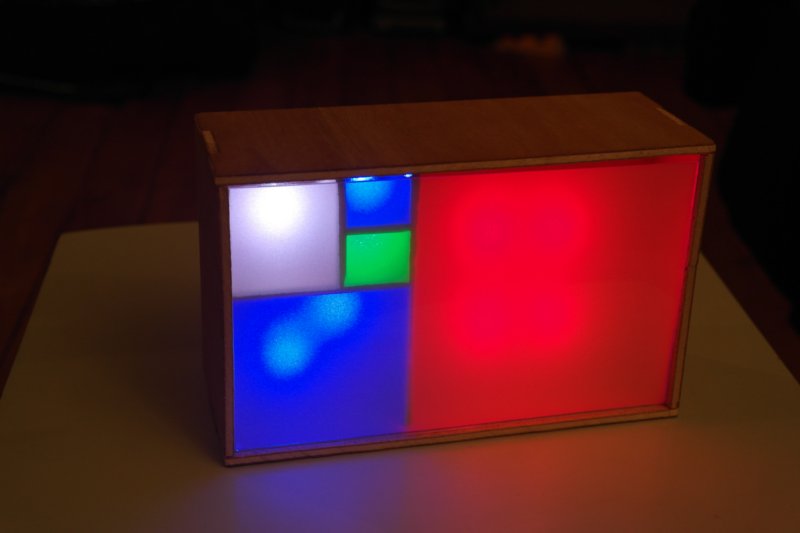
Exemple, on the below picture :
We addition red and blue squares for hours, it gives :
1 + 3 + 5 = 9h
and green and blue squares for minutes, multiplied by 5, it gives : (1 + 1 + 3 ) * 5 = 25min
il est donc ici 9h25
Yes
 Français
 English
 Deutsch
 Español
 Italiano
 Português