This activity is a great example of how Arduino can be integrated with a circuit to create something appealing to all ages and genders. It will introduce the participants to a new component (RGB strips) and is a great next step from simple circuitry as it involves more advanced techniques, such as soldering, and many different components such as a battery, switch, resistors and transistors.

Difficulté
Facile
Durée
11 mois
Catégories
Électronique
Coût
1 USD ($)
Sommaire
- 1 Introduction
- 2 Étape 1 - Design Your Glowing Component on TinkerCAD
- 3 Étape 2 - Print Out Your Design
- 4 Étape 3 - Create Your Temporary Tester Circuit
- 5 Étape 4 - Coding Your Arduino
- 6 Étape 5 - Testing Your Temporary Circuit
- 7 Étape 6 - Change Your Code
- 8 Étape 7 - Create Your Permanent Circuit: Step 1 - Attach Pin Headers
- 9 Étape 8 - Create Your Permanent Circuit: Step 2 - Attach Transistors and Ground
- 10 Étape 9 - Create Your Permanent Circuit: Step 3 - Connect Resistors and Connecting Wires
- 11 Étape 10 - Integrating Your Circuit With Your 3D Printed Component
- 12 Étape 11 - Connect Your RGB Strips If Needed
- 13 Étape 12 - Attach Your Battery and Switch
- 14 Étape 13 - Add Your Glowing Back to the 3D Printed Component
- 15 Étape 14 - Connecting Your 3D Printed Part to the Circuit
- 16 Étape 15 - Watch Your Butterfly Glow!
- 17 Commentaires
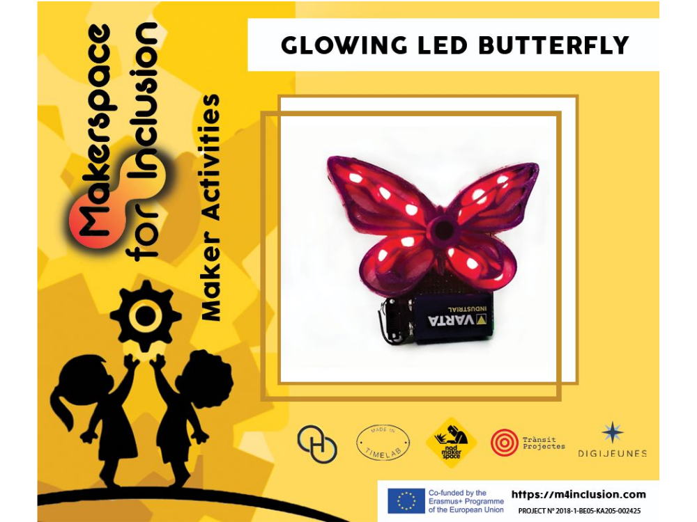
Introduction
The glowing LED butterfly uses RGB strips programmed by Arduino to illuminate the 3D printed body. Here the example presents a butterfly design, but any shape could be used. The glowing of the strip and the colour pattern can be programmed using Arduino.
With the integration of a battery and a switch, the creation can be taken home and displayed anywhere. It is a fun and flexible activity which provides a slightly higher level of complexity and can be spread out over multiple sessions by integrating many different skills and techniques including 3D printing, soldering and electronic prototyping.
AGES: 11 to 18 years
TIME: 5+ hours
Activity's Aims and Learning Objectives
- Creating something more complex from the beginning, which also involves all stages such as designing and testing before making it more permanent and transportable.
- Working with small components that require patience and high levels of concentration
- Able to work flexibly and adapt the design or steps taken if something breaks or gets damaged throughout the process.
- Creating a functional object using different techniques from different disciplines.
- A project with a longer time frame which can help support time management. There are different sections of the activity that can be spread out across different sessions.
- Designing 3D printable object using TinkerCAD
- Using a 3D printer to create a component
- Programming an Arduino and involving it in a circuit
- Using Arduino to create a programme which works with RGB strips and can change the lights as they wish
- Gain experience with electronic prototyping and testing circuits
- Gain experience with soldering and creating permanent circuits
- Learn about the different circuit components
- Creating something that is appealing to them
Supplies:
For the butterfly (or other design to glow)
- Computer with access to TinkerCAD
- 3D printer
- Felt (or other appropriate material for backing)
- Glue gun
For programming element
- Computer with Arduino software downloaded
- Arduino Uno board
For Circuits (temporary and permanent)
- RGB LED strips
- 3 x [100 to 220 ohm resistors]
- 3 x [NPN transistors such as TIP120]
- Multiple male to male solderless breadboard jumper cables
- Breadboard
- Wire
- Wire strippers
- Soldering iron
- Solder
- 9V battery
- 9V battery strap
- Small prototyping printed circuit board (PCB)
- Header pins (breakaway male)
- Switch (in this example we use a slide switch)
- heat shrink wrapping tubes (not necessary but are advised!)
Matériaux
Outils
Étape 1 - Design Your Glowing Component on TinkerCAD
Use TinkerCad to design the component that will be 3D printed. This is a great opportunity to develop your computer aided design (CAD) skills!
What to think about..
- Needs to have holes for the light to go through
- Needs to be big enough to hide the Arduino and PCB
- Needs to be able to sit on the top of the 9V battery
Pre-made butterfly design can be found through this link


Étape 2 - Print Out Your Design
Save and download your design as a .stl and upload into your printer software.
Slice your design, making sure you pay attention to the printer settings. Things to think about..
- Is the highest quality necessary for this print?
- How could you save time on the printing?
- How could you save material on this print?
- Are supports needed anywhere? Do you have any large amounts of overhang?
- Should you add a raft to help with the removal of the print from the machine?
Upload onto a SD card or USB stick (depending on your printer) and hit print!
Étape 3 - Create Your Temporary Tester Circuit
Set up a temporary circuit using a bread board and solderless jumper cables.
Set up your circuit as shown in the diagram
Things to note:
- There is a transistor for each of the Red, Blue and Green inputs of the RGB strip
- Each transistor has 3 pins, one for GROUND, one for SIGNAL INPUT and one for SIGNAL OUTPUT
- The signal input pin of each transistor is connected to a pin on the Arduino board which will be controlled by the Arduino code - this will tell it when this colour should illuminate or not.
- The signal output pin of each transistor is connected to the corresponding connection on the RGB strip.
- The Vin pin from the Arduino is connected to the 12V+ connection point on the RGB strip. This means that the power source is coming the computer when it is connected rather than a battery


Étape 4 - Coding Your Arduino
To check that your new temporary circuit works, you need to code your Arduino.
Insert this basic code into your Arduino window and upload it to the board. If uploaded successfully, your RGB strip should start to glow.
https://drive.google.com/open?id=1mJ-rji0tkuz_fEMDP0bslL46oOHOpRaGKp9tPOCiM_A
IMPORTANT: The voltage the strip is receiving is much lower than 12V, therefore the LEDs will not be very bright and hard to see when they light up. You will need to pay close attention to see if they are working or not!
Étape 5 - Testing Your Temporary Circuit
Now you know the code on the board is uploaded and working, you need to get more power to the RGB strip by using the 9V battery.
Insert the battery into the circuit by:
Connecting the negative port to a ground pin on the Arduino
Connect the positive port, via crocodile clip cable, to the crocodile clip which is connecting the Vin of the Arduino board to the 12V connection on the RGB strip. As shown in the picture. NOTE: This connection is so that the battery supplies energy to the Arduino board and the RGB strip.
Once all attached, your strip should light up a lot brighter!


Étape 6 - Change Your Code
Now that all of this working you can go back to Arduino and start to understand the code.
Here you can modify the code so that the lights flash in the sequence you would like and with different colours!
Some extra explanation of the code and different changes you can make are given below, but you will have to play around with it and the value for the outputs to make it illuminate in the colours and pattern you want!
When changing your code, some things to think about include:
- What colour do I want my butterfly to glow?
- Do you want your butterfly to change colours? How fast and how often?
- Do you want you butterfly to repeat its sequence or stop after a while?
- What values of r, g and b are needed for certain colours?
To test your code, make sure to re-plug in your board to the computer and upload it, then reconnect the board with the temporary circuit and watch your light show!
https://drive.google.com/open?id=1nIrkKnFvZsXjCcwkL9yXGUat_1BSNQKr6zOC6wpvwvc
Étape 7 - Create Your Permanent Circuit: Step 1 - Attach Pin Headers
Now you know that everything works and your happy with your code, you can make everything more permanent by getting rid of the big crocodile clips and jumper cables and moving onto a prototyping circuit board.
You can gradually transfer your circuit from your breadboard onto your circuit board as you wish, but here are the steps we recommend you follow:
- Attach a 4 pin header and 8 pin header in the correct places to line up with the Vin, ground, ground pins and numbered pins (most importantly 3, 5 and 6) on the other side. Solder these into place

Étape 8 - Create Your Permanent Circuit: Step 2 - Attach Transistors and Ground
- Attach the 3 transistors at the top of the circuit board. Solder these into place.
- Ground the 3rd pin of each transistor by taking a wire from the header pin connected with the ground pin of the Arduino and connecting it to the 3rd pin of each transistor.
Make sure good connections are made with the solder. You should be able to do this with 2 pieces of wire as shown in the image.

Étape 9 - Create Your Permanent Circuit: Step 3 - Connect Resistors and Connecting Wires
- Connect resistors between the input pin of the transistor and the corresponding header pin.
These header pins should be the pins connected to the numbered pins on the Arduino. It is important that these match up with the pin numbers you assigned in the code. (e.g 3 = blue, 5 = red, 6 = green)
- Add wires to the transistor output pins, which will later connect to the RGB strip.
NOTE: best to keep these wires long, to make sure they reach the connections later on and length can be removed after.
- Add long wires to the header pins at Vin and a second ground pin on the Arduino board. These will be connected to the 12V connection on the RGB strip and battery later on.
NOTE: again, its best to keep these wires long so that they can reach their connections and the length can be removed after. Test your prototype circuit using crocodile clips, connecting the long wires to the correct connections (the 12V connection on RGB strip, the battery and the R, G and B connections on the RGB strip).

Étape 10 - Integrating Your Circuit With Your 3D Printed Component
Now you have the circuit ready to go, you can create your glowing object!
Take your 3D printed piece and draw around it onto felt.
Cut out this felt to make a backing.
On this piece of felt work out where you would like to locate you RGB stripes. This may require you to cut up smaller strips and position them separately.


Étape 11 - Connect Your RGB Strips If Needed
It is easiest to have just one connection point from the strips to your circuit board. For this you need to connect the different strips, either with solder if the pieces are close together (A) or with small pieces of wire (B), as shown in the picture.
In this example we have two connection points, coming from each side of the butterfly.
Check all your soldered connections work by using crocodile clips to connect up your butterfly with the circuit board, Arduino and battery.


Étape 12 - Attach Your Battery and Switch
Now everything is tested, you can attach the battery to the bottom of the circuit board using a glue gun.
Attach the battery strap to the head of the battery.
Using a glue gun attach a switch to the top of the battery strap.
Connect the black wire (negative), from the battery strap, to the long wire coming from the ground pin of the Arduino (via the circuit board)
Connect the red wire (positive), from the battery strap, to the first pin of the switch.
Take the long wire connected to the Vin pin of the Arduino (via the circuit board), cut to length and solder to the middle pin of the switch. This will complete the circuit through the switch, so that it can control when the RGB strips will light up.


Étape 13 - Add Your Glowing Back to the 3D Printed Component
Cut out another piece of felt the same size and shape as your butterfly (or 3D printed component).
Use the glue gun to stick this backing onto your 3D printed piece.
Use the glue gun to stick your felt with RGB strips onto your backed butterfly, so that the RGB strips are sandwiched between the two pieces of felt and stuck onto the back of the butterfly.

Étape 14 - Connecting Your 3D Printed Part to the Circuit
If you only have ONE group of connection wires coming from the 3D printed component...
Connect the correct wire from the butterfly to the correct wire from the circuit board and transistors.
Solder the 2 wires together, making sure you reduce the length of the wire so that there is not a lot of excess when the butterfly sits on the battery.
Connect the 12V connection wire from the RGB strip to the middle pin of the switch (the same pin that the battery's +ve output, or red wire, is connected to).
If you have TWO groups of connection wires coming from the 3D printed component...
You will need to connect these together at the back of the butterfly.
You can directly solder the two wires together or add additional wire between them. You will want them to join near the top of the butterfly so they can be easily accessed and connected to the wires coming from the circuit board.
Cut out a third piece of felt, the same size and shape as the butterfly and stick this over the top using the glue gun, hiding any unnecessary wires, but insuring a small part of the connected wires are poking out so that they can be connected with the wires from the circuit board and battery.
Now follow the instruction above for ONE group of connection wires to finish the connections with the circuit board.
NOTE:
You can use shrinking plastic wraps to get rid of any unwanted exposed wire. It may be best to label the wires with the colour/connection as you go to make sure the correct connections are made.

Étape 15 - Watch Your Butterfly Glow!
Now you should be able to switch your switch and watch your butterfly glow!
Position your butterfly onto the battery and attach with a glue gun.
Decorate you butterfly with glitter, paint or sequences that will shine as it glows!

Draft
 Français
 English
 Deutsch
 Español
 Italiano
 Português