


Introduction
In this tutorial, I share the journey of how I built the FlyPi, without any previous electronics experience, so I could feed my insatiable urge to see how things work. Microscopy offers a lens to explore each visual frontier with its wonderful new perspectives and illuminates minuscule life regularly unobserved. This is an amazing experiences for anyone curious of what lies beneath our immediate visual capabilities. One main constraint for curious students, researchers and/or educators to look deeper into the micro world, is access to effective scientific tools. This is likely due to high prices set by development under a patent/scarcity methodology. Building your own FlyPi is a relatively easy and cost effective way to to get around this limiting factor. FlyPi is an all-in-one biology lab with powerful “off-the-shelf” electronic elements (Raspberry Pi & Arduino nano). It's modularity offers a fast, effective and low cost way to have better experimental control by customizing for specific needs and most importantly enables accessibility to research and explore the microscopic world around us. Just putting it together is a great learning experience for everyone not immediately comfortable with electronics. Some People have even begun to join scientific efforts in pursuing solutions to their local problems!
Steps
1- Understanding Modularity: Deciding what to include or exclude in the build
2- Gathering materials & Creating parts: Options to buy parts from kitspace, link to original github repository
Due to modularity, not all parts are necessary for basic functionality. (Repository has more detailed bill of material files)
3- Building PCB hardware: Quick overview of the PCB build
4- Software Installation: How to install interface and useful imagej FIJI software on SD card
5- Launching the FlyPi: Putting it all together to start collecting image data!
Matériaux
Monitor
Computer mouse - USB
Keyboard - USB
3D print files (.stl) : Under 'Files' tab above
Custom PCB (Principle Component Board parts can be found on: https://kitspace.org/boards/github.com/prometheus-science/flypi/ )
Outils
Soldering Iron, Solder
Computer with:
- SD card reader
- Internet connection
3D printer
Étape 1 - Understanding Modularity
1- Modularity: Broadly speaking, is the degree to which a system's components may be separated and recombined, often with the benefit of flexibility and variety in use. Examples of modularity are things like cars, computers, solar panels, lego blocks and biological cells. Principles behind modularity posit that systems should be built from cohesive loosely coupled components, sometimes referred to as modules, with a defined function or purpose.
The FlyPi is designed in a modular fashion to optimize diverse capabilities. The base pieces are the raspberry pi, raspberry pi cam, the PCB with the Arduino and the 3D printed housing. The raspberry pi acts as the computer for the camera and the PCB/Arduino controls the mechanical functions of the modules. Modules include the Peltier module (temperature controlled plate), the multicolour LED ring, the UV light, the fans for the UV light and Peltier, the thermostat and the indication LED for the Peltier. It's important to point out that all modules do not have to be added which can save time and money. If desired, modules can be added at any point.
To begin, I determined which modules I wanted to have. I decided to keep all but the servo motor that provided some (x,y) axis movement for the slide. My samples were large enough that manual movement would be sufficient. I also knew I wanted to customize the design for an (x,y,z) axis movement to a hydraulic syringe that could be manually manipulated(that's another tutorial).


Étape 2 - Gathering Materials & Creating Parts
2- Gathering materials & Creating Parts: Not all parts are necessary to order for basic functionality. The repository has a detailed bill of materials that can be tailored to specific needs.
- Electronic parts can be ordered from this kitspace page (lists have been conveniently compiled in various online market shopping carts):
https://kitspace.org/boards/github.com/prometheus-science/flypi/
- 3D print files can be found in the files tab above. I started printing at the local fablab (fabrication laboratory) after ordering the parts I needed to build the microscope. This way I would have the body ready when the electronics arrived.

Étape 3 - Building PCB board
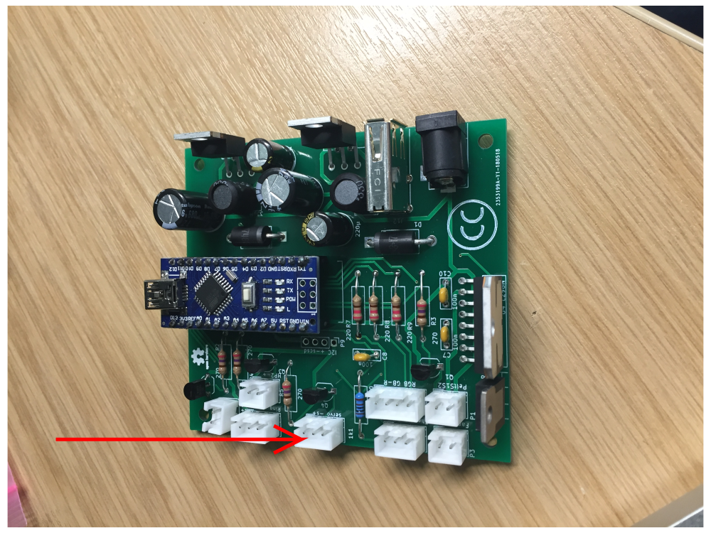
The PCB board is organized in the following modules:
a) power 1 - 12v to 5v converter dedicated to power the Raspberry Pi
b) power 2 - 12v to 5v converter to power LEDs, LED ring, Thermistor and devices on the I2C port
c) High power LED / 5V general module 1 - Port that can be used with high power LEDs or any other component that takes up to 5V (uses a NPN transistor, PWM capable).
d) High power LED / 5V general module 2 - Port that can be used with high power LEDs or any other component that takes up to 5V.
e) LED ring module - used to power and control the LED ring
f) servo motor module - used to power and control a continuous servo motor
g) Peltier element module - comprised of fan, RGB led, thermistor and peltier element ports.
A fully populated port should look like the one in the image


Étape 4 - Adding Modules
4- Software Installation: How to install useful software on SD card
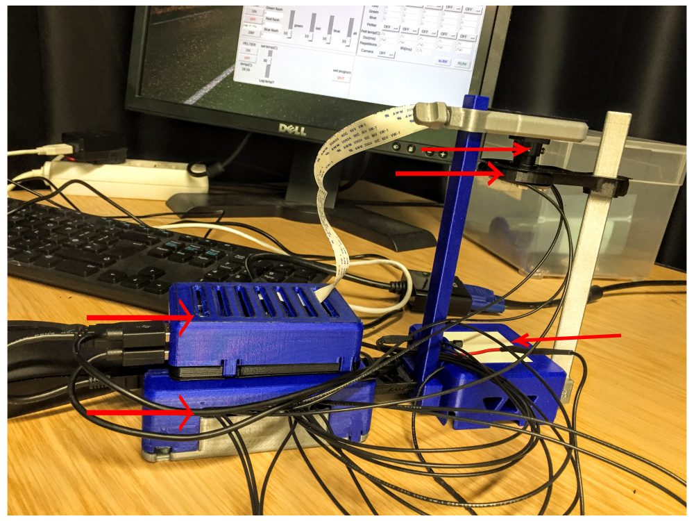
Étape 5 - Launching the FlyPi
5- Launching FlyPi program: Putting it all together to start collecting image data!
Published
 Français
 English
 Deutsch
 Español
 Italiano
 Português