(set pageLanguageSource property) |
|||
| Ligne 1 : | Ligne 1 : | ||
{{ {{tntn|Tuto Details}} | {{ {{tntn|Tuto Details}} | ||
| − | |||
| − | |||
| − | |||
|Type=Creation | |Type=Creation | ||
| − | |Area=Robotics, | + | |Area=Electronics, Play and Hobbies, Robotics |
| + | |Tags=robot, Arduino, | ||
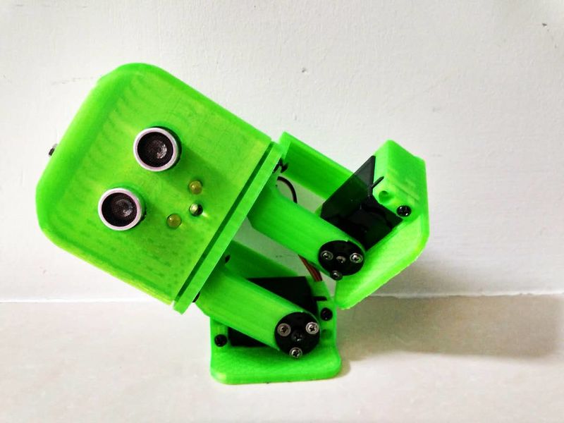
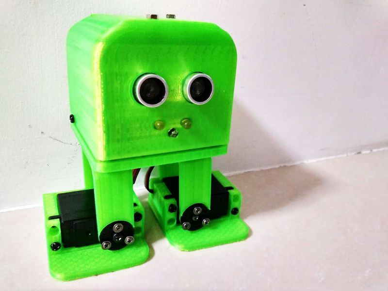
|Description=<translate><!--T:1--> Tito is a Biped dancing DIY robot, derivative from Zowi and Bob, basically has been adapted to an standard Arduino UNO board with easier connections and supports.</translate> | |Description=<translate><!--T:1--> Tito is a Biped dancing DIY robot, derivative from Zowi and Bob, basically has been adapted to an standard Arduino UNO board with easier connections and supports.</translate> | ||
|Difficulty=Medium | |Difficulty=Medium | ||
| Ligne 13 : | Ligne 11 : | ||
|Licences=Attribution-ShareAlike (CC BY-SA) | |Licences=Attribution-ShareAlike (CC BY-SA) | ||
|Main_Picture=Tito (11).jpg | |Main_Picture=Tito (11).jpg | ||
| + | |SourceLanguage=none | ||
| + | |Language=en | ||
| + | |IsTranslation=0 | ||
}} | }} | ||
{{ {{tntn|Introduction}} | {{ {{tntn|Introduction}} | ||
| Ligne 18 : | Ligne 19 : | ||
}} | }} | ||
{{ {{tntn|Materials}} | {{ {{tntn|Materials}} | ||
| + | |Step_Picture_00=Tito (6).jpg | ||
|Material=<translate><!--T:3--> | |Material=<translate><!--T:3--> | ||
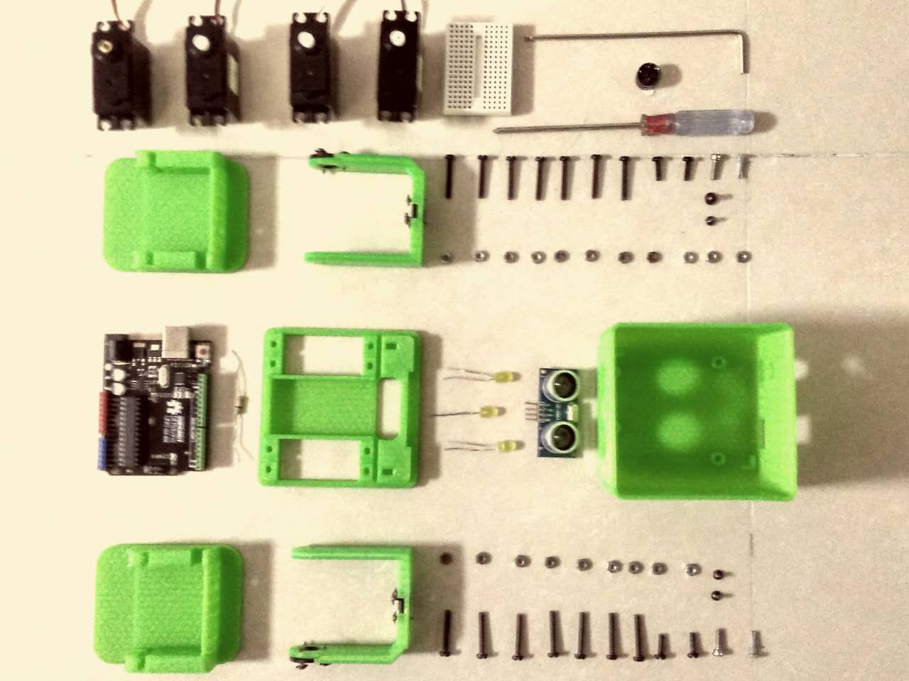
Arduino UNO | Arduino UNO | ||
| Ligne 32 : | Ligne 34 : | ||
3d print Foot R | 3d print Foot R | ||
3d print Foot L</translate> | 3d print Foot L</translate> | ||
| − | |Tools=3d printer, allen key and screwdriver | + | |Tools=<translate>3d printer, allen key and screwdriver</translate> |
| − | |||
| − | |||
| − | |||
| − | |||
| − | |||
| − | |||
| − | |||
| − | |||
}} | }} | ||
| − | {{Separator}} | + | {{ {{tntn|Separator}}}} |
{{ {{tntn|Tuto Step}} | {{ {{tntn|Tuto Step}} | ||
| + | |Step_Picture_00=3dprinter.JPG | ||
|Step_Title=<translate><!--T:4--> 3D print parts</translate> | |Step_Title=<translate><!--T:4--> 3D print parts</translate> | ||
|Step_Content=<translate><!--T:5--> | |Step_Content=<translate><!--T:5--> | ||
3D .stl files here: http://www.thingiverse.com/thing:1378605 | 3D .stl files here: http://www.thingiverse.com/thing:1378605 | ||
Find a way to 3d print the parts, they are designed for no supports so is very easy to print with 20% infill and 0.2mm resolution.</translate> | Find a way to 3d print the parts, they are designed for no supports so is very easy to print with 20% infill and 0.2mm resolution.</translate> | ||
| − | |||
| − | |||
| − | |||
| − | |||
| − | |||
| − | |||
}} | }} | ||
{{ {{tntn|Tuto Step}} | {{ {{tntn|Tuto Step}} | ||
| + | |Step_Picture_00=Tito (3).jpg | ||
| + | |Step_Picture_01=Tito parts.jpg | ||
|Step_Title=<translate><!--T:6--> Pre assemble</translate> | |Step_Title=<translate><!--T:6--> Pre assemble</translate> | ||
|Step_Content=<translate><!--T:7--> There is many was to build Tito, but one recommendation is before the connect the servos is to assemble the servo disk pieces to the legs, then put the servos in the body and the feet..</translate> | |Step_Content=<translate><!--T:7--> There is many was to build Tito, but one recommendation is before the connect the servos is to assemble the servo disk pieces to the legs, then put the servos in the body and the feet..</translate> | ||
| − | |||
| − | |||
| − | |||
| − | |||
| − | |||
| − | |||
}} | }} | ||
{{ {{tntn|Tuto Step}} | {{ {{tntn|Tuto Step}} | ||
| + | |Step_Picture_00=conection.JPG | ||
|Step_Title=<translate><!--T:8--> The Schematic</translate> | |Step_Title=<translate><!--T:8--> The Schematic</translate> | ||
|Step_Content=<translate><!--T:9--> | |Step_Content=<translate><!--T:9--> | ||
| Ligne 71 : | Ligne 57 : | ||
HC-SR04 Ultrasound sensor (not connected in the schematic; trig for pin 8 and echo for pin 9). | HC-SR04 Ultrasound sensor (not connected in the schematic; trig for pin 8 and echo for pin 9). | ||
During the making process you may need to disconnect and connect constantly so just keep this schematic present for further fixes.</translate> | During the making process you may need to disconnect and connect constantly so just keep this schematic present for further fixes.</translate> | ||
| − | |||
| − | |||
| − | |||
| − | |||
| − | |||
| − | |||
}} | }} | ||
{{ {{tntn|Tuto Step}} | {{ {{tntn|Tuto Step}} | ||
| + | |Step_Picture_00=Tito align.jpg | ||
|Step_Title=<translate><!--T:10--> Test the position of the servos</translate> | |Step_Title=<translate><!--T:10--> Test the position of the servos</translate> | ||
|Step_Content=<translate><!--T:11--> In the picture the cables are disconnected but the idea here is to upload a code to the Arduino board (https://github.com/agomezgar/tutoriales/tree/master/tutorialZowi3/prepararServosparaMontaje) that will put the all servos in 90 degrees and then fix the right angle for the crank discs in the body and the feet. Tito should be in a neutral position like the photo. then you can fix all the servos with the screw axis.</translate> | |Step_Content=<translate><!--T:11--> In the picture the cables are disconnected but the idea here is to upload a code to the Arduino board (https://github.com/agomezgar/tutoriales/tree/master/tutorialZowi3/prepararServosparaMontaje) that will put the all servos in 90 degrees and then fix the right angle for the crank discs in the body and the feet. Tito should be in a neutral position like the photo. then you can fix all the servos with the screw axis.</translate> | ||
| − | |||
| − | |||
| − | |||
| − | |||
| − | |||
| − | |||
}} | }} | ||
{{ {{tntn|Tuto Step}} | {{ {{tntn|Tuto Step}} | ||
| + | |Step_Picture_00=Tito (30).JPG | ||
|Step_Title=<translate><!--T:12--> Assemble Arduino board</translate> | |Step_Title=<translate><!--T:12--> Assemble Arduino board</translate> | ||
|Step_Content=<translate><!--T:13--> This design make it easy to fix any Arduino Uno compatible board (in my case a DFRduino UNO) in the head part, you can use up to 4 screws.</translate> | |Step_Content=<translate><!--T:13--> This design make it easy to fix any Arduino Uno compatible board (in my case a DFRduino UNO) in the head part, you can use up to 4 screws.</translate> | ||
| − | |||
| − | |||
| − | |||
| − | |||
| − | |||
| − | |||
}} | }} | ||
{{ {{tntn|Tuto Step}} | {{ {{tntn|Tuto Step}} | ||
| + | |Step_Picture_00=Tito (15).jpg | ||
|Step_Title=<translate><!--T:14--> Final assembly</translate> | |Step_Title=<translate><!--T:14--> Final assembly</translate> | ||
|Step_Content=<translate><!--T:15--> If all connections are secured you can close the head part and fix it to the body using the lateral screws.</translate> | |Step_Content=<translate><!--T:15--> If all connections are secured you can close the head part and fix it to the body using the lateral screws.</translate> | ||
| − | |||
| − | |||
| − | |||
| − | |||
| − | |||
| − | |||
}} | }} | ||
{{ {{tntn|Tuto Step}} | {{ {{tntn|Tuto Step}} | ||
| + | |Step_Picture_00=Tito program.jpg | ||
|Step_Title=<translate><!--T:16--> Programming</translate> | |Step_Title=<translate><!--T:16--> Programming</translate> | ||
|Step_Content=<translate><!--T:17--> | |Step_Content=<translate><!--T:17--> | ||
| Ligne 114 : | Ligne 80 : | ||
Just connect your USB cable to Arduino and upload the codes | Just connect your USB cable to Arduino and upload the codes | ||
There are many programmed movements for the robot like walk different directions, raise, tilt and dance.</translate> | There are many programmed movements for the robot like walk different directions, raise, tilt and dance.</translate> | ||
| − | |||
| − | |||
| − | |||
| − | |||
| − | |||
| − | |||
}} | }} | ||
{{ {{tntn|Notes}} | {{ {{tntn|Notes}} | ||
| Ligne 126 : | Ligne 86 : | ||
Code: https://github.com/bqlabs/zowi | Code: https://github.com/bqlabs/zowi | ||
}} | }} | ||
| + | {{ {{tntn|Tuto Status}}}} | ||
{{Tuto_Status</translate> | {{Tuto_Status</translate> | ||
|Complete=Yes | |Complete=Yes | ||
}} | }} | ||
{{Separator}} | {{Separator}} | ||
Version du 22 septembre 2017 à 17:38
Introduction
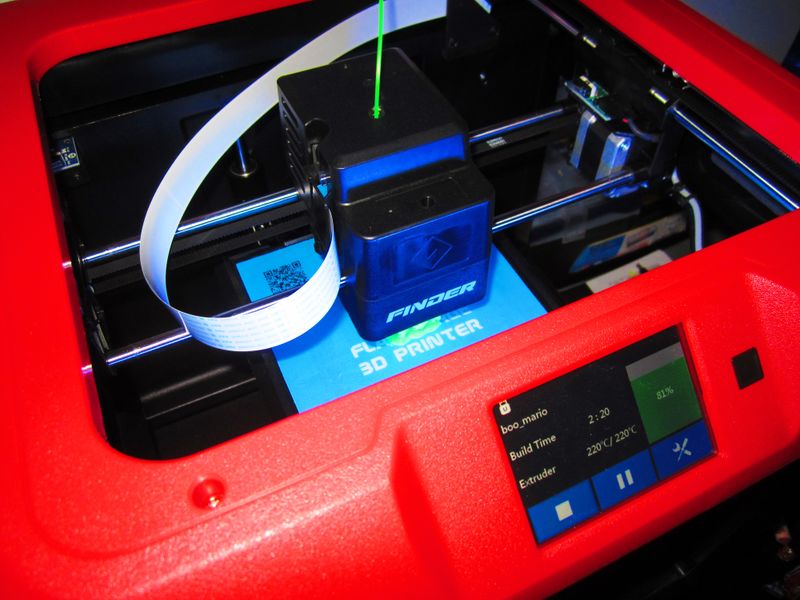
Étape 1 - 3D print parts
3D .stl files here: http://www.thingiverse.com/thing:1378605 Find a way to 3d print the parts, they are designed for no supports so is very easy to print with 20% infill and 0.2mm resolution.
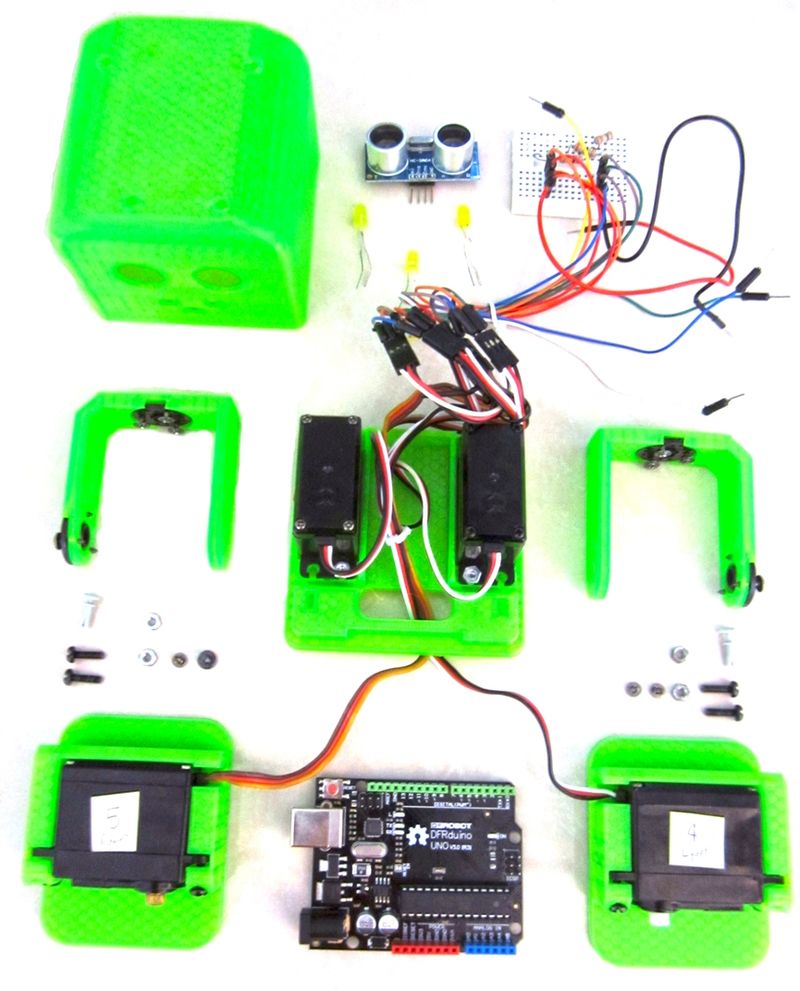
Étape 2 - Pre assemble
There is many was to build Tito, but one recommendation is before the connect the servos is to assemble the servo disk pieces to the legs, then put the servos in the body and the feet..
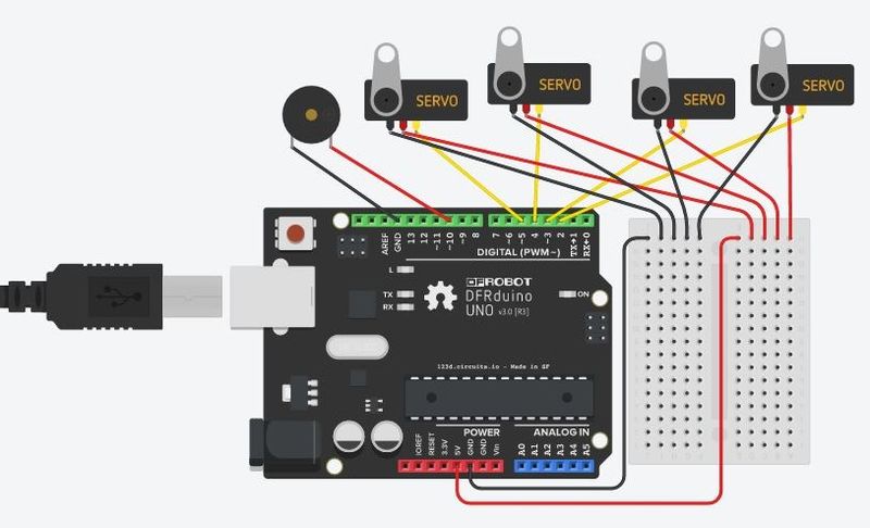
Étape 3 - The Schematic
Follow the picture for the connections. HC-SR04 Ultrasound sensor (not connected in the schematic; trig for pin 8 and echo for pin 9). During the making process you may need to disconnect and connect constantly so just keep this schematic present for further fixes.
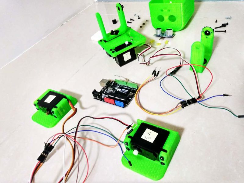
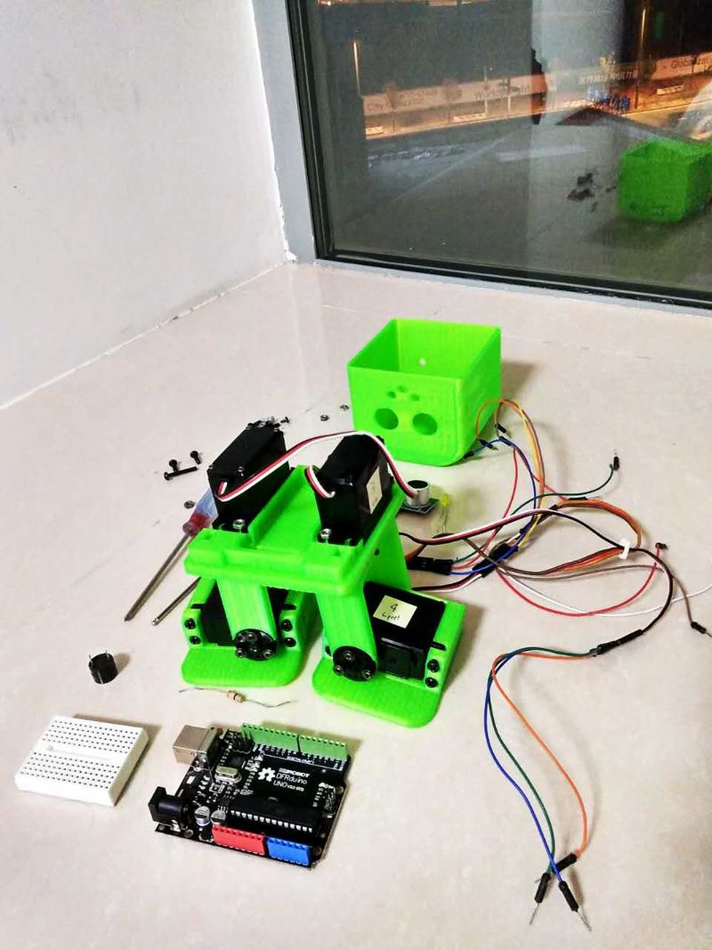
Étape 4 - Test the position of the servos
In the picture the cables are disconnected but the idea here is to upload a code to the Arduino board (https://github.com/agomezgar/tutoriales/tree/master/tutorialZowi3/prepararServosparaMontaje) that will put the all servos in 90 degrees and then fix the right angle for the crank discs in the body and the feet. Tito should be in a neutral position like the photo. then you can fix all the servos with the screw axis.
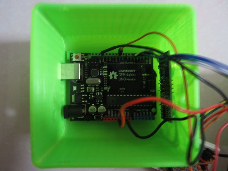
Étape 5 - Assemble Arduino board
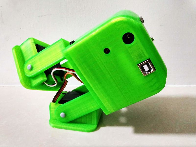
This design make it easy to fix any Arduino Uno compatible board (in my case a DFRduino UNO) in the head part, you can use up to 4 screws.
Étape 6 - Final assembly
If all connections are secured you can close the head part and fix it to the body using the lateral screws.
Étape 7 - Programming
All libraries and Arduino source code are in this Github repository: https://github.com/bqlabs/zowi Just connect your USB cable to Arduino and upload the codes There are many programmed movements for the robot like walk different directions, raise, tilt and dance.
Notes et références
3D print files: http://www.thingiverse.com/thing:137860 Code: https://github.com/bqlabs/zowi
Yes
 Français
 English
 Deutsch
 Español
 Italiano
 Português