(Cette version a été marquée pour être traduite) |
(update property name) |
||
| (3 révisions intermédiaires par 2 utilisateurs non affichées) | |||
| Ligne 1 : | Ligne 1 : | ||
| − | {{ | + | {{Tuto Details |
|Main_Picture=Analogic_Drawing_Pad_9.PNG | |Main_Picture=Analogic_Drawing_Pad_9.PNG | ||
|Licences=Attribution (CC BY) | |Licences=Attribution (CC BY) | ||
| Ligne 15 : | Ligne 15 : | ||
|IsTranslation=0 | |IsTranslation=0 | ||
}} | }} | ||
| − | {{ | + | {{Introduction |
|Introduction=<translate><!--T:2--> | |Introduction=<translate><!--T:2--> | ||
In this activity, kids experiment with an analogic drawing pad, to grasp the concept of a cnc machine moving along its x, y, and z axis. | In this activity, kids experiment with an analogic drawing pad, to grasp the concept of a cnc machine moving along its x, y, and z axis. | ||
| Ligne 32 : | Ligne 32 : | ||
Une version française de ce tutoriel est disponible [https://drive.google.com/file/d/18ChJt80UuK5LsJJhfxp3u89zOOxUavh8/view?usp=sharing ici].</translate> | Une version française de ce tutoriel est disponible [https://drive.google.com/file/d/18ChJt80UuK5LsJJhfxp3u89zOOxUavh8/view?usp=sharing ici].</translate> | ||
}} | }} | ||
| − | {{ | + | {{TutoVideo |
|VideoType=Youtube | |VideoType=Youtube | ||
|VideoURLYoutube=https://www.youtube.com/watch?v=Wv8DprKltYs&feature=youtu.be | |VideoURLYoutube=https://www.youtube.com/watch?v=Wv8DprKltYs&feature=youtu.be | ||
}} | }} | ||
| − | {{ | + | {{Materials |
| + | |Step_Picture_00=Piccolo_cnc_drawing_robot_Erasmus_logo.jpg | ||
|Material=<translate><!--T:7--> | |Material=<translate><!--T:7--> | ||
10x M4x25mm screws | 10x M4x25mm screws | ||
| Ligne 49 : | Ligne 50 : | ||
=== [https://fr.opitec.com/opitec-web/articleNumber/809350 <u>2x big pulleys</u>] === <!--T:10--> | === [https://fr.opitec.com/opitec-web/articleNumber/809350 <u>2x big pulleys</u>] === <!--T:10--> | ||
| − | === [https://fr.opitec.com/opitec-web/articleNumber/801433 <u>8 x small pulleys</u>] === | + | === [https://fr.opitec.com/opitec-web/articleNumber/801433 <u>8 x small pulleys</u>] === <!--T:12--> |
| − | |||
| − | |||
| − | <!--T:12--> | ||
1x A4 size MDF board, 3mm thick | 1x A4 size MDF board, 3mm thick | ||
| Ligne 69 : | Ligne 67 : | ||
|Tools=<translate></translate> | |Tools=<translate></translate> | ||
}} | }} | ||
| − | {{ | + | {{Separator}} |
| − | {{ | + | {{Tuto Step |
|Step_Title=<translate><!--T:16--> Draw the different parts of the pad on the wooden board</translate> | |Step_Title=<translate><!--T:16--> Draw the different parts of the pad on the wooden board</translate> | ||
|Step_Content=<translate><!--T:17--> | |Step_Content=<translate><!--T:17--> | ||
| Ligne 80 : | Ligne 78 : | ||
|Step_Picture_01=Analogic_Drawing_Pad_1.PNG | |Step_Picture_01=Analogic_Drawing_Pad_1.PNG | ||
}} | }} | ||
| − | {{ | + | {{Tuto Step |
|Step_Title=<translate><!--T:19--> Lock the pulleys to the board, using screws and bolts and washers</translate> | |Step_Title=<translate><!--T:19--> Lock the pulleys to the board, using screws and bolts and washers</translate> | ||
|Step_Content=<translate><!--T:20--> Use 3 bolts in total for the small pulleys (the blue ones) and 5 bolts plus 2 washers for the big pulleys (the control pulleys -in red)</translate> | |Step_Content=<translate><!--T:20--> Use 3 bolts in total for the small pulleys (the blue ones) and 5 bolts plus 2 washers for the big pulleys (the control pulleys -in red)</translate> | ||
|Step_Picture_00=Analogic_Drawing_Pad_2.PNG | |Step_Picture_00=Analogic_Drawing_Pad_2.PNG | ||
}} | }} | ||
| − | {{ | + | {{Tuto Step |
|Step_Title=<translate><!--T:21--> Wrap the nylon wire around the blue pulleys and the control pulleys</translate> | |Step_Title=<translate><!--T:21--> Wrap the nylon wire around the blue pulleys and the control pulleys</translate> | ||
|Step_Content=<translate><!--T:22--> | |Step_Content=<translate><!--T:22--> | ||
| Ligne 106 : | Ligne 104 : | ||
|Step_Picture_02=Analogic_Drawing_Pad_7.PNG | |Step_Picture_02=Analogic_Drawing_Pad_7.PNG | ||
}} | }} | ||
| − | {{ | + | {{Tuto Step |
|Step_Title=<translate><!--T:27--> Use some hot glue to stick the ends of the skewers to the nylon wire</translate> | |Step_Title=<translate><!--T:27--> Use some hot glue to stick the ends of the skewers to the nylon wire</translate> | ||
|Step_Content=<translate><!--T:28--> If you’ve assembled all parts in the correct way, both skewers should be able to move freely around the pad (along the x and y axis of the pad).</translate> | |Step_Content=<translate><!--T:28--> If you’ve assembled all parts in the correct way, both skewers should be able to move freely around the pad (along the x and y axis of the pad).</translate> | ||
|Step_Picture_00=Analogic_Drawing_Pad_8.PNG | |Step_Picture_00=Analogic_Drawing_Pad_8.PNG | ||
}} | }} | ||
| − | {{ | + | {{Tuto Step |
|Step_Title=<translate><!--T:29--> Create the support for the pen</translate> | |Step_Title=<translate><!--T:29--> Create the support for the pen</translate> | ||
|Step_Content=<translate><!--T:30--> We now need to create a support for the pen. Use a piece of cardboard to create it, then glue it to the other piece of cardboard hosting the skewers.</translate> | |Step_Content=<translate><!--T:30--> We now need to create a support for the pen. Use a piece of cardboard to create it, then glue it to the other piece of cardboard hosting the skewers.</translate> | ||
|Step_Picture_00=Analogic_Drawing_Pad_9.PNG | |Step_Picture_00=Analogic_Drawing_Pad_9.PNG | ||
}} | }} | ||
| − | {{ | + | {{Notes |
|Notes=<translate><!--T:31--> | |Notes=<translate><!--T:31--> | ||
This tutorial was produced as part of the FabEdu project, co-financed by the Erasmus + Programme of the European Union. | This tutorial was produced as part of the FabEdu project, co-financed by the Erasmus + Programme of the European Union. | ||
| + | |||
| + | <!--T:33--> | ||
| + | Project number: 2017-1-FR02-KA205-012767 | ||
<!--T:32--> | <!--T:32--> | ||
The content of this publication does not reflect the official opinion of the European Union. Responsibility for the information and views expressed therein lies entirely with the author(s).</translate> | The content of this publication does not reflect the official opinion of the European Union. Responsibility for the information and views expressed therein lies entirely with the author(s).</translate> | ||
}} | }} | ||
| − | {{ | + | {{Tuto Status |
|Complete=Published | |Complete=Published | ||
}} | }} | ||
Version actuelle datée du 9 décembre 2019 à 12:24
Sommaire
- 1 Introduction
- 2 Video d'introduction
- 3 Étape 1 - Draw the different parts of the pad on the wooden board
- 4 Étape 2 - Lock the pulleys to the board, using screws and bolts and washers
- 5 Étape 3 - Wrap the nylon wire around the blue pulleys and the control pulleys
- 6 Étape 4 - Use some hot glue to stick the ends of the skewers to the nylon wire
- 7 Étape 5 - Create the support for the pen
- 8 Notes et références
- 9 Commentaires
Introduction
In this activity, kids experiment with an analogic drawing pad, to grasp the concept of a cnc machine moving along its x, y, and z axis.
The analogic pad has a pen mounted onto it that can move along the x and y axis of the pad.
Kids can attempt to draw simple geometrical shapes such as squares, rectangles, triangles, etc. on the analogic pad, and later observe a cnc machine (such as a 3D printer) that moves along its x, y, and z axis to create a 3D object. They will notice that the basic working principles of the two systems are very similar.
What follows is a step by step tutorial on how to build your own analogic drawing pad.
Youtube
Matériaux
10x M4x25mm screws
34x M4 Nuts
2x big pulleys
8 x small pulleys
1x A4 size MDF board, 3mm thick
2 long wooden skewers
nylon wire
Outils
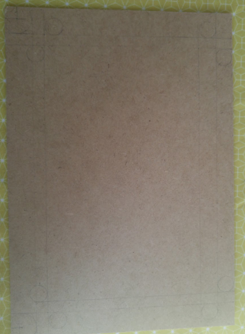
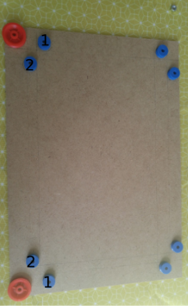
Étape 1 - Draw the different parts of the pad on the wooden board
You will need to draw 10 pulleys in total. To draw the pulleys, just place them on the board and draw their contour.
Place de pulleys marked with “1” at 2cm from the sides of the board, and 5cm from the bottom of the board (the bottom of the board is the longest side).
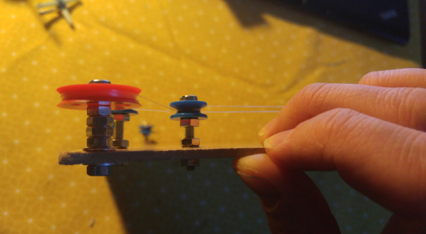
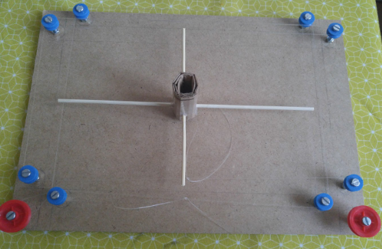
Étape 2 - Lock the pulleys to the board, using screws and bolts and washers
Use 3 bolts in total for the small pulleys (the blue ones) and 5 bolts plus 2 washers for the big pulleys (the control pulleys -in red)
Étape 3 - Wrap the nylon wire around the blue pulleys and the control pulleys
Watch this video to learn how
You can also watch this video if you struggle with the wiring.
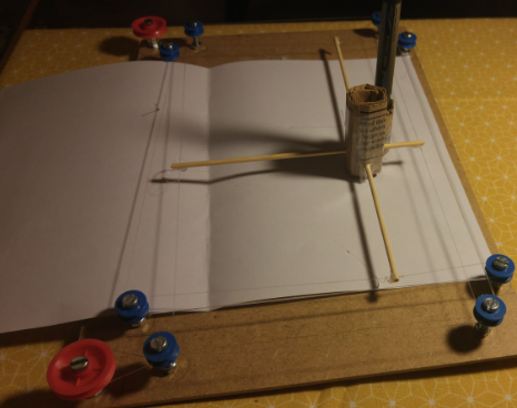
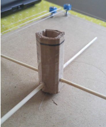
Use a piece of cardboard to place two wooden skewers at 90° angles with respect to one another.
The skewers need to be long enough to reach the nylon wire on the top bottom left and right of the pad.
Alternatively, you can use straws to accomplish this step.
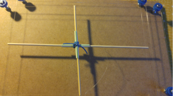
Étape 4 - Use some hot glue to stick the ends of the skewers to the nylon wire
If you’ve assembled all parts in the correct way, both skewers should be able to move freely around the pad (along the x and y axis of the pad).
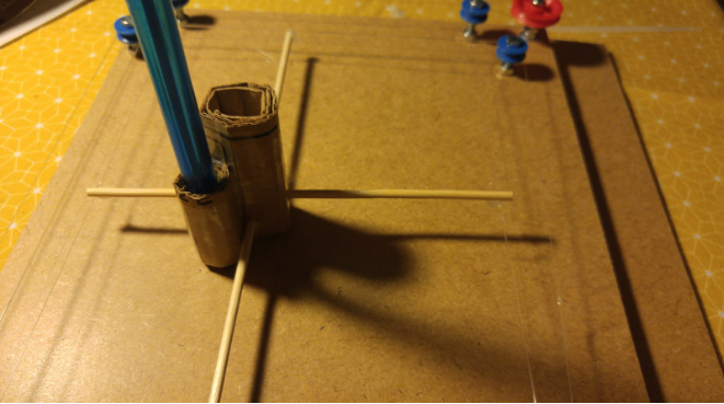
Étape 5 - Create the support for the pen
We now need to create a support for the pen. Use a piece of cardboard to create it, then glue it to the other piece of cardboard hosting the skewers.
Notes et références
This tutorial was produced as part of the FabEdu project, co-financed by the Erasmus + Programme of the European Union.
Project number: 2017-1-FR02-KA205-012767
The content of this publication does not reflect the official opinion of the European Union. Responsibility for the information and views expressed therein lies entirely with the author(s).
Published

 Français
 English
 Deutsch
 Español
 Italiano
 Português