| Ligne 55 : | Ligne 55 : | ||
|Step_Content='''Définissez l’esthétique et la disposition électrique de votre pièce''' | |Step_Content='''Définissez l’esthétique et la disposition électrique de votre pièce''' | ||
| − | + | Decidez ou chaque composent va se placer et trouver comment vous allez les coudre ensemble, avec le moins possible de fils qui se croissent. Faites un schéma pour pouvoir vous y référer pendant votre travail. la photo ci-contre montre le schéma pour ma veste. Le point pour l'alimentation (+) est en rouge, la masse (-) en noir, les LEDs en vert et les boutons en violet. | |
}} | }} | ||
{{ {{tntn|Tuto Step}} | {{ {{tntn|Tuto Step}} | ||
Version du 23 août 2017 à 17:12
Sommaire
- 1 Étape 1 - Conception
- 2 Étape 2 - Important note about the power supply
- 3 Étape 3 - Transfer the sketch to your garment
- 4 Étape 4 - Preparation before sewing
- 5 Étape 5 - Sew your power supply and LilyPad to your jacket
- 6 Étape 6 - Sew the + petal of your LilyPad down
- 7 Étape 7 - Put fabric glue on each of your knots
- 8 Étape 8 - Test your stitching
- 9 Étape 9 - Sew on your turn signal LEDs
- 10 Étape 10 - Test your turn signals
- 11 Étape 11 - Place your control switches
- 12 Étape 12 - Sew in your switches
- 13 Étape 13 - Sew a single LED onto the sleeve of each arm
- 14 Étape 14 - Program your jacket
- 15 Étape 15 - Go biking
- 16 Commentaires
Matériaux
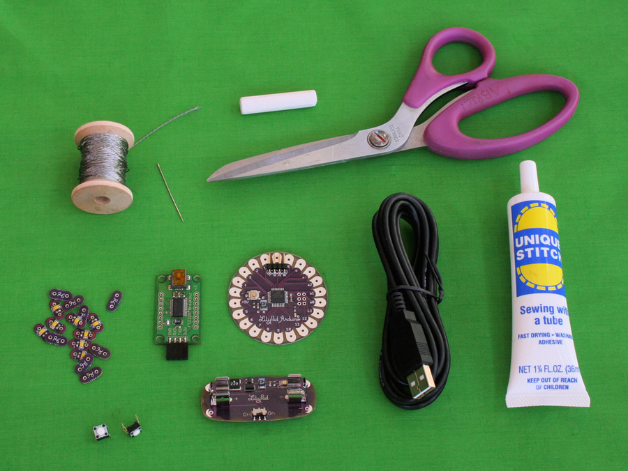
- LilyPad Arduino main board
- FTDI connector
- mini USB cable
- LilyPad power supply
- 16 LilyPad LEDs
- 2 push button switches
- a spool of 4-ply conductive thread
- un vêtement ou un morceau de tissu
information: J'ai concu le LilyPad, donc je vais gagner quelque $ si vous en achetez un
Outils
- un multimetre digital, avec test de continuité avec bipper
- une ou deux aiguille
- un marquer ou une craie
- puffy fabric paint
- de la colle pour vêtements
- un metre
- une paire de ciseaux
- scotch double face (optionnel)
- une machine à coudre (optionnel)
Étape 1 - Conception
Définissez l’esthétique et la disposition électrique de votre pièce
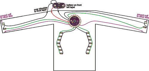
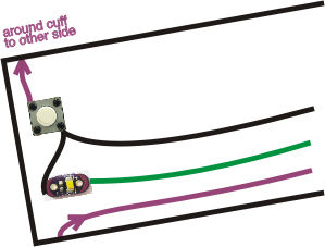
Decidez ou chaque composent va se placer et trouver comment vous allez les coudre ensemble, avec le moins possible de fils qui se croissent. Faites un schéma pour pouvoir vous y référer pendant votre travail. la photo ci-contre montre le schéma pour ma veste. Le point pour l'alimentation (+) est en rouge, la masse (-) en noir, les LEDs en vert et les boutons en violet.
Étape 2 - Important note about the power supply
As you design, plan to keep your power supply and LilyPad main board close to each other. If they are too far apart, you are likely to have problems with your LilyPad resetting or just not working at all.
Why? Conductive thread has non-trivial resistance. (The 4-ply silver-coated thread from SparkFun that comes with the LilyPad starter kit has about 14 ohms/foot.) Depending on what modules you're using in your construction, your LilyPad can draw up to 50 milliamps (mA) of current, or .05 Amps. Ohm's law says that the voltage drop across a conductive material--the amount of voltage that you lose as electricity moves through the material--is equal to the resistance of the conductive material times the amount of current that is flowing through it.
For example, if your LilyPad is a foot away from the power supply, the total resistance of the conductive material that attaches your LilyPad to your power supply is about 28 ohms. (14 Ohms in the conductive thread that leads from the negative terminal of the power supply to the negative petal on the LilyPad and 14 Ohms in the conductive thread that ties the positive terminals together). This means we can expect a drop of 1.4 Volts (28 Ohms * .05 Amps.) This means that while 5 Volts is coming out of the power supply, the LilyPad will only be getting 3.6 Volts (5 Volts - 1.4 Volts). Once the voltage at the LilyPad drops below about 3.3 Volts, it will reset. The resistance of the traces from + on the power supply to + on the LilyPad and - on the power supply to - on the LilyPad should be at most 10 Ohms. Plan the distance accordingly.
If all of this was confusing, don't worry! Just keep the LilyPad and power supply close to each other in your design.
Étape 3 - Transfer the sketch to your garment
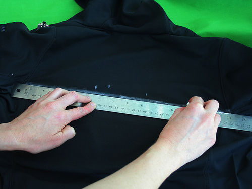
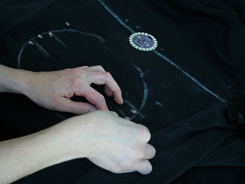
Use chalk or some other non-permanent marker to transfer your design to the garment. If you want, use a ruler to make sure everything is straight and symmetrical.
Use double sided tape to temporarily attach LilyPad pieces to your garment. This will give you a good sense of what your final piece will look like. It will also keep everything in place and, as long as the tape sticks, make your sewing easier.
Étape 4 - Preparation before sewing
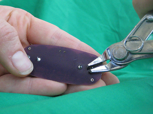
First, trim the leads off of the back of the power supply
Get out your LilyPad power supply piece and trim the metal parts that are sticking out the back of it. Small clippers like the ones shown in the photo work well, but you can also use scissors.
Stabilize your battery on the fabric
Generally, you want to do everything you can to keep the power supply from moving around on the fabric. I recommend gluing or sewing the battery down before starting on the rest of the project. You may also want to glue or sew something underneath the power supply to help prevent it from pulling on the fabric and bouncing around as you move.
If you are working on a thin or stretch piece of fabric--first of all, reconsider this choice! It's much easier to work on a heavy piece of non-stretchy fabric. If you are determined to forge ahead with a delicate fabric, choose the location for your power supply wisely. It's the heaviest electronic module, so put it somewhere where it will not distort the fabric too badly. definitely glue or sew something underneath the power supply.
Étape 5 - Sew your power supply and LilyPad to your jacket
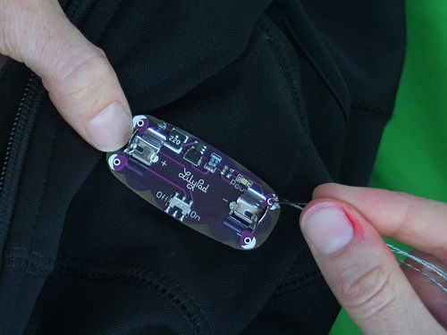
Sew the + petal of the power supply down to your garment
Cut a 3-4 foot length of conductive thread. Thread your needle, pulling enough of the thread through the needle that it will not fall out easily. Tie a knot at the end of the longer length of thread. Do not cut the thread too close to the knot or it will quickly unravel.
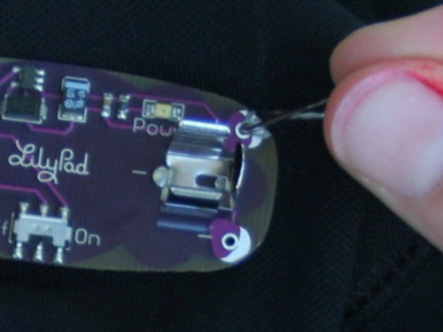
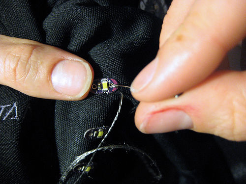
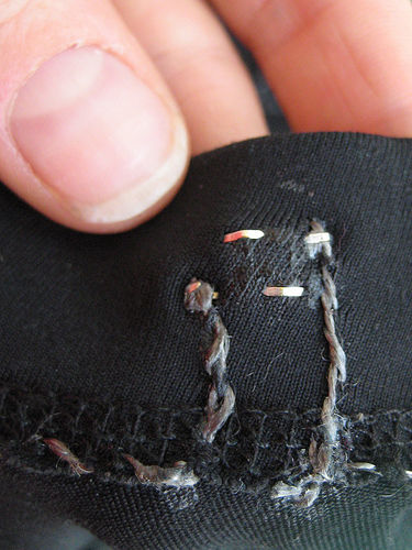
Coming from the back of the fabric to the front, poke the needle into the fabric right next to the + petal on the power supply and then, from the front of the fabric, pull it through. The knot at the end of the thread will keep the thread from pulling out of the fabric. Now make a stitch going into the hole in the hole in the + petal on the power supply. Do this several more times, looping around from the back of the fabric to the front, going through the + petal each time.
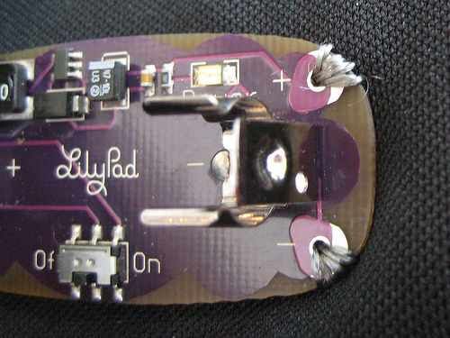
Pay special attention to this stitching. It is the most important connection that you'll sew in your project. You want to make sure you get excellent contact between the petals on the power supply and your conductive thread. Go through the hole several times (at least 5) with your stitching. Keep sewing until you can't get your needle through anymore. Do not cut your thread, just proceed to the next step.
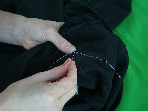
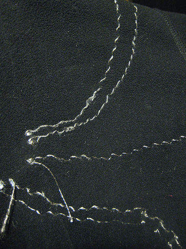
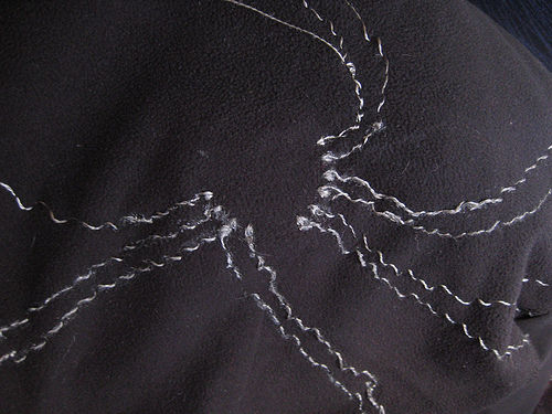
Sew from the battery to the LilyPad. Once you've sewn the + petal of the battery down, make small neat stitches to the + petal of your LilyPad. I used a jacket with a fleece lining and stitched only through the inner fleece lining so that no stitches were visible on the outside of the jacket.
Étape 6 - Sew the + petal of your LilyPad down
Sew the + petal of your LilyPad down, finishing the connection.
When you reach the LilyPad, sew the + petal down to the fabric with the conductive thread. Just like you were with the battery petal, you want to be extra careful to get a robust connection here. This stitching is making the electrical connection between your power supply and LilyPad.
When you are done with this attachment, sew away from the LilyPad about an inch along your stitching, tie a knot, and cut your thread about an inch away from the knot so that your knot won't come untied.
Étape 7 - Put fabric glue on each of your knots
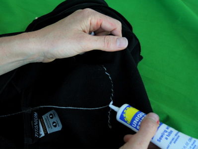
Put fabric glue on each of your knots to keep them from unraveling.
Once the glue dries, trim the thread close to each knot.
Étape 8 - Test your stitching
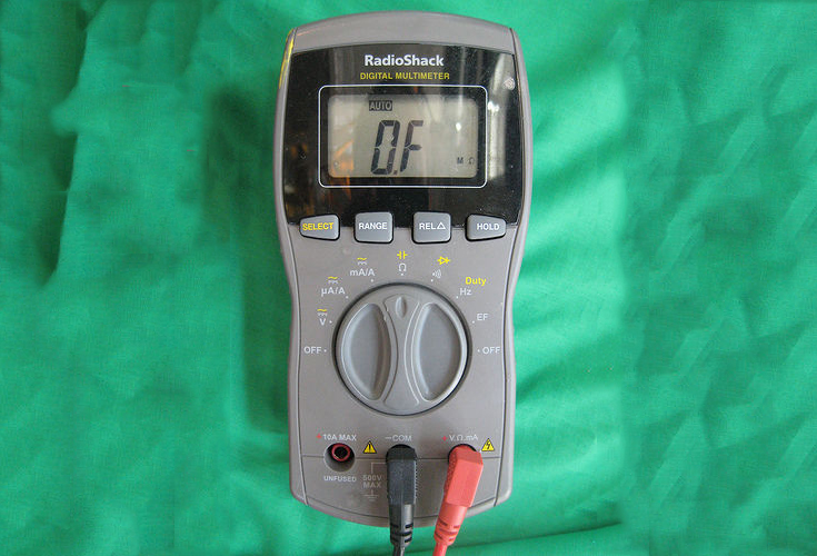
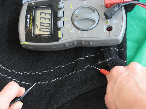
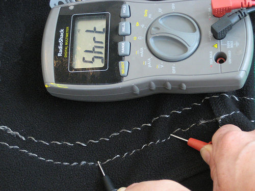
Measure the resistance of your stitching. Get out your multimeter and put it on the resistance measuring setting. Measure from power supply + to LilyPad + and power supply - to LilyPad -. If the resistance of either of these traces is greater than 10 ohms, reinforce your stitching with more conductive thread.
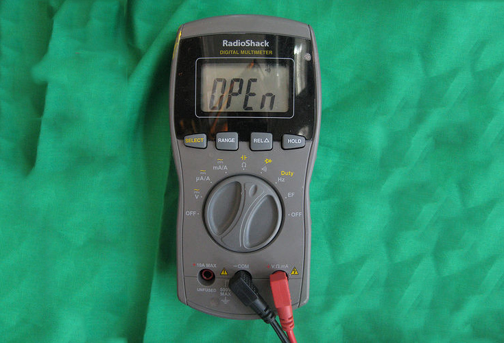
Put a AAA battery into the power supply and flip the power supply switch to the on position. The red light on the power supply should turn on. If it doesn't and you're sure you flipped the switch, quickly remove the battery and check for a short between your + and - stitches. (Most likely there is a piece of thread that's touching both the - and + stitching somewhere.) You can test for a short between + and - by using the beeping continuity tester on your multimeter.
Also check the resistance between the + and - stitching. If the resistance is less than 10K Ohms or so, you've got a mini-short (probably a fine conductive thread hair that is touching both + and -) that you need to find and correct.
If the power supply does turn on, look at your LilyPad. It should blink quickly each time you press its switch. Once these connections are working properly, turn off the power supply and remove the battery.
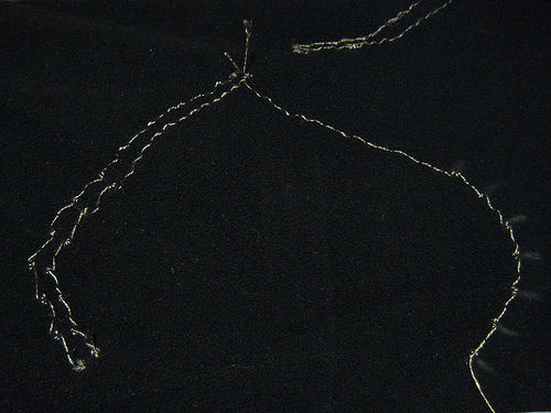
Insulate your power and ground stitching So, your jacket is now full of uninsulated conductive stitches. This is fine when a body is inside of it. A body will prevent sewn traces from contacting each other. But when the jacket is off of a person and you bend or fold it, traces will touch each other and short out. To fix this problem, cover your traces with puffy fabric paint (or another insulator like a satin stitch in regular thread). But, you don't want to cover traces until you're sure that everything works! So, use good judgment in when to coat traces.
Étape 9 - Sew on your turn signal LEDs
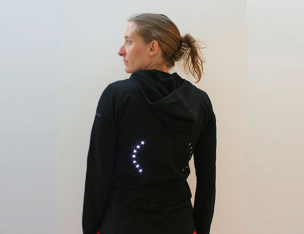
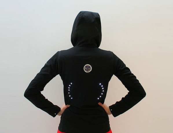
Sew in your left and right signals.
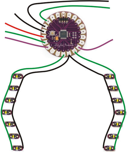
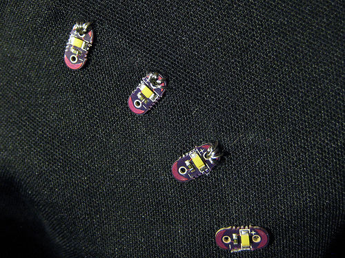
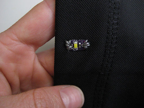
Using the same techniques you used to sew the power supply to the LilyPad, attach all of the + petals of the lights for the left turn signal together and to a petal on the LilyPad (petal 9 for me) and all of the + petals for the right signal together and to another LilyPad petal (11 for me). Attach all of the - petals of the lights together and then to either the - petal on the LilyPad or another LilyPad petal (petal 10 for me). Refer back to my design sketches if any of this is confusing.
Étape 10 - Test your turn signals
Load a program onto your LilyPad that blinks each turn signal to make sure all of your sewing is correct.
Here's my test program: Fichier:Turn signal code.pdf
If your layout is the same as mine, you can just copy and paste this program into your Arduino window.
insulate your turn signal stitches Cover your traces with puffy fabric paint. Remember, you don't want to cover traces until you're sure that everything works! Use good judgment in when to coat traces.
Étape 11 - Place your control switches
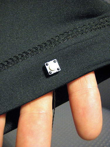
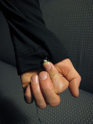
Find a spot for your switches where they'll be easy to press when you're riding your bike. I mounted mine on the underside of my wrists. I found a good spot by trying out different places. Check out the photos to see what I mean.
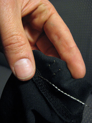
Once you've found a good position, push the legs of the switch through the fabric and bend them over on the inside of the fabric.
Étape 12 - Sew in your switches
Sew your switches into the garment. Sew 1 leg to the switch input petal on the LilyPad and another leg, one that is diagonally across from the first , to ground or another LilyPad petal. I used petal 6 for the switch input on the left side and petal 12 for switch input on the right side. I used - for the - connection on the left side, but petal 4 for the - connection on the right side. Refer back to my design drawings if any of this is confusing.
When you're done sewing, go back and reinforce the switch connections with glue. You don't want your switches to fall out of their stitching.
Étape 13 - Sew a single LED onto the sleeve of each arm
These will give you essential feedback about which turn signal is on. They'll flash to tell you what the back of your jacket is doing, so make sure they're in a visible spot. Sew the + petals of each LED to a LilyPad petal and the - petals of each LED to the - side of the switch (the - trace you sewed in the last step). I used petal 5 for the LED + on the left side and petal 3 for the LED + on the right side. Again, refer back to my design drawings if any of this is confusing.
As always, remember to glue and trim knots and be careful not to create any shorts.
Once you sew both wrist LEDs, you're done with the sewing phase of the project! Now, on to programming...
Étape 14 - Program your jacket
Decide on the behavior you want I wanted the left switch to turn on the left turn signal for 15 seconds or so, and the right switch to do the same thing for the right signal. Pressing a switch when the corresponding turn signal is on should turn the signal off. Pressing both switches at the same time should put the jacket into nighttime flashing mode. The wrist mounted LEDs should provide feedback about the current state of the jacket.
Here's the code I wrote to get that behavior: Fichier:Turn signal biking jacket.pdf
Program your jacket To program your garment, copy and paste my code into an Arduino window and load it onto the LilyPad. You may have to make some small adjustments first depending on where you attached lights and switches. Play with delays to customize your blinking patterns.
Étape 15 - Go biking
Plug your battery back in and see if it works and...go biking!
Insulate the rest of your traces
Cover the rest of your traces with puffy fabric paint. Again, don't coat anything until you're sure it works.
About washing
Your creation is washable. Remove the battery and wash the garment by hand with a gentle detergent.
Note: silver coated threads will corrode over time and their resistance will gradually increase with washing and wear. To limit the effects of corrosion, insulate and protect your traces with puffy fabric paint or some other insulator. You can also revive exposed corroded traces with silver polish. Try this on a non-visible area first to see what it does to your fabric!
Yes
 Français
 English
 Deutsch
 Español
 Italiano
 Português